JP4046855B2 - Circumferential displacement measuring device - Google Patents
Circumferential displacement measuring device Download PDFInfo
- Publication number
- JP4046855B2 JP4046855B2 JP18299498A JP18299498A JP4046855B2 JP 4046855 B2 JP4046855 B2 JP 4046855B2 JP 18299498 A JP18299498 A JP 18299498A JP 18299498 A JP18299498 A JP 18299498A JP 4046855 B2 JP4046855 B2 JP 4046855B2
- Authority
- JP
- Japan
- Prior art keywords
- displacement
- rotation
- detector
- measuring
- circumferential surface
- Prior art date
- Legal status (The legal status is an assumption and is not a legal conclusion. Google has not performed a legal analysis and makes no representation as to the accuracy of the status listed.)
- Expired - Fee Related
Links
- 238000006073 displacement reaction Methods 0.000 title claims description 173
- 238000005259 measurement Methods 0.000 claims description 36
- 238000001514 detection method Methods 0.000 claims description 19
- 230000002093 peripheral effect Effects 0.000 description 57
- 238000009434 installation Methods 0.000 description 9
- 230000033001 locomotion Effects 0.000 description 5
- 238000000034 method Methods 0.000 description 5
- 238000012360 testing method Methods 0.000 description 5
- 239000011435 rock Substances 0.000 description 4
- XLYOFNOQVPJJNP-UHFFFAOYSA-N water Substances O XLYOFNOQVPJJNP-UHFFFAOYSA-N 0.000 description 4
- 238000012669 compression test Methods 0.000 description 3
- 239000004567 concrete Substances 0.000 description 3
- 238000011065 in-situ storage Methods 0.000 description 3
- 239000002689 soil Substances 0.000 description 3
- 238000012795 verification Methods 0.000 description 3
- 230000006835 compression Effects 0.000 description 2
- 238000007906 compression Methods 0.000 description 2
- 238000007405 data analysis Methods 0.000 description 2
- 239000012530 fluid Substances 0.000 description 2
- 239000002184 metal Substances 0.000 description 2
- 241001125929 Trisopterus luscus Species 0.000 description 1
- 238000004458 analytical method Methods 0.000 description 1
- 230000004323 axial length Effects 0.000 description 1
- 238000005452 bending Methods 0.000 description 1
- 230000005540 biological transmission Effects 0.000 description 1
- 238000010276 construction Methods 0.000 description 1
- 230000008602 contraction Effects 0.000 description 1
- 238000013461 design Methods 0.000 description 1
- 230000000694 effects Effects 0.000 description 1
- 230000002452 interceptive effect Effects 0.000 description 1
- 239000000463 material Substances 0.000 description 1
- 238000012986 modification Methods 0.000 description 1
- 230000004048 modification Effects 0.000 description 1
- 230000000452 restraining effect Effects 0.000 description 1
- 238000007789 sealing Methods 0.000 description 1
- 238000010998 test method Methods 0.000 description 1
- 238000004804 winding Methods 0.000 description 1
Images
Landscapes
- A Measuring Device Byusing Mechanical Method (AREA)
- Length Measuring Devices With Unspecified Measuring Means (AREA)
- Investigating Strength Of Materials By Application Of Mechanical Stress (AREA)
Description
【0001】
【発明の属する技術分野】
本発明は、円孔の内周面や円柱の外周面等の円周面の変位を計測する変位計測装置に関する。更に詳述すると、本発明は、円周面の変位を回転方向と半径方向と軸方向の成分ごとに分けて計測する変位計測装置に関する。
【0002】
【従来の技術】
地盤や岩盤等に形成された円孔や円管等の内周面のように円柱面状である内周面の変位を計測する際は、内周面の回転方向と半径方向と軸方向との各成分ごとに別個に変位を計測する。また、土や岩石やコンクリートの三軸試験では、円柱の外周面の変位を半径方向及び軸方向ごとに別個に計測する。さらに、これら土や岩石やコンクリートの中空ねじり試験では、円筒の内周面と外周面での変位を回転方向(即ちねじり方向)と半径方向と軸方向ごとに別個に計測する。これらの場合には、円周面の回転方向変位と半径方向変位と軸方向変位との計測がそれぞれ以下のように行われる。
【0003】
円周面の回転方向変位を計測するには、円周面から外れた位置に固定した回転角計測器を円周面の回転中心と同軸にして設けると共にこの回転角計測器を円周面に1本以上のリンクで結合する。そして、円周面が回転するとリンクを介して回転角計測器が回転して回転角を計測することができる。または、円周面上に固定した1点の円周方向の移動変位を計測して、円周面の既知の半径から回転角を算出することもできる。
【0004】
円周面の半径方向変位を計測するには、次の各方法がある。▲1▼円周面に歪みゲージを貼付して周方向の歪みを計測したり円周面上に固定した2点間の距離の変化を計測することにより円周長の変化を算出して、若しくは円周長の変化を直接計測して、この円周長の変化に基づいて半径方向の変位を算出することができる。▲2▼計測する箇所を密閉空間にして非圧縮性の流体を流入出可能に充満させておく。そして、円周面の変位による流体の流入出量、即ち容積と密閉空間の軸方向長さとを計測して、これらの値に基づき半径方向変位を算出することができる。▲3▼円周面の直径や半径を直接計測して、半径方向変位を得ることができる。
【0005】
円周面の軸方向変位は、長さの変化を測定可能な変位計測器を使用して直接計測することができる。
【0006】
【発明が解決しようとする課題】
しかしながら、上述した円周面の変位の計測方法では変位の3つの成分ごとにそれぞれ計測器を設けているので、測定作業が煩雑であると共に設置コストが高くなってしまう。また、回転方向変位の計測を回転角計測器で行う一方、軸方向変位の計測を長さ変位計測器で行っているので、各計測器の検定が煩雑であると共に次元の異なる計測値を得ることからデータの解析が煩雑であった。
【0007】
そこで、本発明は、測定作業やデータ解析が容易であると共に設置コストが安価な円周面の変位計測装置を提供することを目的とする。
【0008】
【課題を解決するための手段】
かかる目的を達成するため、請求項1記載の円周面の変位計測装置は、円周面の回転方向変位を計測する回転方向変位の計測手段と、円周面の半径方向変位を計測する半径方向変位の計測手段と、円周面の軸方向変位を計測する軸方向変位の計測手段とのうちの少なくとも2つの計測手段を備えると共に、備える計測手段は、円周面の回転中心を中心にして回転可能な駆動部材と、当該駆動部材の回転角を計測する回転角計測器とを共通にしている。
【0009】
ここで、本明細書中では「円周面」とは中心線に直交する断面が真円である円柱面を意味している。
【0010】
したがって、円周面の回転方向と半径方向と軸方向との3成分の変位のうちの少なくとも2つの成分の変位を共通の回転角計測器を使用して計測することができる。このため、単一の回転角計測器の使用により複数の成分の変位を計測できるので、計測作業が容易になると共に設置コストを安価にすることができ、しかも変位計測装置の小型化を図ることができる。また、回転方向変位の計測と軸方向変位の計測とをいずれも回転角計測器による回転角の計測結果を利用して求めることができるので、計測器の検定を容易にできるように成ると共にデータの解析を容易に行うことができるようになる。
【0011】
また、請求項1記載の円周面の変位計測装置では、回転方向変位の計測手段は、円周面上に固定した回転方向検出体と、駆動部材の回転に伴って回転すると共に回転方向検出体を検出する回転方向検出器とを備えるようにしている。
【0012】
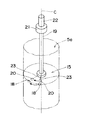
したがって、回転方向変位は、図5に示すように回転角計測器により計測された値をそのまま利用して得ることができる。
【0013】
さらに、請求項1記載の円周面の変位計測装置では、半径方向変位の計測手段は、円周面上に摺動可能に設置した半径方向検出体と、円周面の回転方向に沿った距離を一定にして半径方向検出体に形成される2つの計測部と、駆動部材の回転に伴って回転すると共に2つの計測部を検出する半径方向検出器とを備えるようにしている。
【0014】
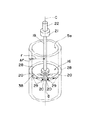
したがって、半径方向変位△rは、図6に示すように回転角計測器により計測された値θ,△θに基づいて数式1により算出することができる。
【0015】
<数1>
△r=r・(△θ/θ)・(1−(△θ/θ))
但し、r :円孔の初期半径
△r:半径方向変位
θ :2つの計測部の間の周方向の変形が無い半径方向検出体を含 む側の初期角度
△θ:θの変位
また、請求項1記載の円周面の変位計測装置では、軸方向変位の計測手段は、円周面上に固定した軸方向検出体と、駆動部材の回転により軸方向に移動する変換器と、該変換器に取り付けられて駆動部材の回転により軸方向に移動すると共に軸方向検出体を検出する軸方向検出器とを備えるようにしている。
【0016】
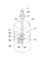
したがって、軸方向変位は、図7に示すように回転角計測器により計測された値に基づいて変換器での回転角と軸方向移動距離の比率を利用して算出することができる。
【0017】
【発明の実施の形態】
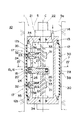
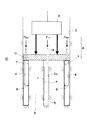
以下、本発明の構成を図面に示す実施の形態の一例に基づいて詳細に説明する。図1〜図7に本発明の円周面の変位計測装置1の一実施形態を示す。本実施形態では、この変位計測装置1を、原位置孔底三軸圧縮試験法(特願平9−318694号)や孔底の中空円筒試験体を利用したプレッシャーメータ試験法(特願平9−318696号)に使用する中空円筒試験体3の中央円孔5の内周面5aの変位を測定するものとしている。この原位置孔底三軸圧縮試験法は、構造物の設計や施工のための地盤調査において地盤10の変形特性及び強度特性を測定するものである。そして、図2に示すように、地盤10を掘り下げて中空円筒試験体3を形成して、中央の円孔5と周囲の円筒形状のスリット4にそれぞれゴムチューブ7を設けて各ゴムチューブ7の内部に高圧水を注入し中空円筒試験体3を変形させて、このときの中央の円孔5の内周面5aの変位を変位計測装置1により測定する。なお、図2中の符号6は中空円筒試験体3の内周面と外周面に内圧Pin及び外圧Poutを加えて変位を与える加圧手段であり、符号8は中空円筒試験体3の外周面の変位を計測する変位計測手段であり、符号9は中空円筒試験体3に軸方向への荷重を与える拘束手段であり、符号11は中空円筒試験体3のキャップである。
【0018】
中央の円孔5のゴムチューブ7には、ほぼ円筒形状で上下部を塞いだシリンダ12が収容されている。このシリンダ12とゴムチューブ7とは上下部同士を密封して結合している。そして、シリンダ12の上部には、シリンダ12及びゴムチューブ7の内外に高圧水を出入り可能にするための流入出口13が形成されている。流入出口13には外部から高圧水をシリンダ12及びゴムチューブ7の内部に供給したり内部の高圧水を逃がすための連結管14が取り付けられている。
【0019】
変位計測装置1は、円周面の回転方向変位を計測する回転方向変位の計測手段15と、円周面の半径方向変位を計測する半径方向変位の計測手段16と、円周面の軸方向変位を計測する軸方向変位の計測手段17とのうちの少なくとも2つの計測手段を備えると共に、備える計測手段は、円周面の回転中心を中心にして回転可能な駆動部材19と、当該駆動部材19の回転角を計測する回転角計測器21とを共通にしている。本実施形態の変位計測装置1は、これら各方向変位の計測手段15,16,17を全て備えている。このため、円周面の回転方向と半径方向と軸方向との3成分の変位を共通の回転角計測器21を使用して計測することができるので、計測作業が容易になると共に設置コストを安価にすることができ、しかも変位計測装置1の小型化を図ることができる。また、計測器21の検定を容易にできるように成ると共にデータの解析を容易に行うことができるようになる。
【0020】
回転方向変位の計測手段15は、円周面である内周面5a上に固定した回転方向検出体18と、駆動部材19の回転に伴って回転すると共に回転方向検出体18を検出する回転方向検出器20とを有している。
【0021】
回転方向検出体18は、円孔5の内周面5a上に固定した点形状の磁石から成るものとしている。駆動部材19は、シリンダ12の上下部を貫通して内周面5aの回転中心C(中心線C)を中心にして回転可能に支持される駆動軸19から成るものとしている。ここで、本実施形態では内周面5aの回転中心と形状中心線とを一致させている。このため、駆動部材19は内周面5aの形状中心線C上に位置している。
【0022】
駆動軸19の上部はシリンダ12の上側に突出して、回転角計測器21及びモータ22が設置されている。よって、モータ22が駆動することにより駆動軸19が回転して、回転角計測器21により駆動軸19の回転角が検出される。また、回転角計測器21の構造は特に限定されず一般的な回転角計測器を使用することができるが、本実施形態ではエンコーダを使用している。本実施形態では回転角計測器21及びモータ22は駆動軸19に同軸に設置されているが、これには限られず歯車機構やベルト機構等の伝達機構を使用して駆動軸19から離隔した位置に設置しても良い。
【0023】
回転方向検出器20は、支持体23を介して駆動軸19に取り付けられている。この支持体23は、ゴムチューブ7に接して内周面5aの周方向に回転するローラ24と、駆動軸19に対してその軸方向に直交して出没可能な軸形状の摺動部25と、回転方向検出器20を回転方向検出体18に向けて押圧する圧縮コイルばねから成る押圧ばね26とを有している。そして、駆動軸19の中央部には軸方向に直交する支持孔27が形成されており、この支持孔27に摺動部25及び押圧ばね26が収容されている。押圧ばね26は支持孔27の底部と摺動部25との間に挟まれて回転方向検出器20を回転方向検出体18に向けて押圧している。このため、内周面5aが拡径しても回転方向検出器20は常に内周面5aに近接している。さらに、シリンダ12の側壁の中央部に周方向に切り欠いた孔部12aを形成して、この孔部12aから回転方向検出器20をシリンダ12の外部に突出させてゴムチューブ7に接触させている。よって、回転方向検出器20はゴムチューブ7を介して回転方向検出体18に向き合っている。
【0024】
また、回転方向検出器20としては、ホール素子等を使用した磁力検出器を採用している。このため、駆動軸19の回転により回転方向検出器20が回転方向検出体18に接近したことを検出することができる。本実施形態では回転方向検出体18と回転方向検出器20を磁石とホール素子を使用する近接センサとしているが、これには限られず例えばノッチや凸部をレーザー変位計等により検出するものやコントラストの高いマークを光学的に検出するものや電磁波発生器からの電磁波を受信機で感知するものとしても良く、既知のまたは新規の他の近接センサを使用することができる。
【0025】
そして、回転方向検出器20が回転方向検出体18に最も接近したときの回転方向検出器20の向いている角度を回転角計測器21により検出するようにする。したがって、回転方向変位を求める際は、図5に示すように回転角計測器21により計測された回転角の変位の計測値をそのまま回転方向変位とすることができる。
【0026】
半径方向変位の計測手段16は、内周面5a上に摺動可能に設置した半径方向検出体38と、内周面5aの回転方向に沿った距離を一定にして半径方向検出体38に形成される2つの計測部29,29と、駆動部材19の回転に伴って回転すると共に2つの計測部29,29を検出する半径方向検出器20とを有している。
【0027】
半径方向検出体38は、円孔5の内周面5a上に設置した一部を切り欠いたほぼ円環形状であると共に回転方向への伸縮がほとんど無い連結部材28と、該連結部材28の両端部に固定された磁石から成る2つの計測部29,29を有している。この連結部材28としては、紐や帯等の線状部材、例えば金属製のリボンやローラ付きチェーン等を使用することができる。この半径方向検出体38はゴムチューブ7の外面により円孔5の内周面5aに押し付けられている。このため、内周面5aの半径方向の変位に容易に追従することができる。また、半径方向検出体38の切り欠いた部分、即ち2つの計測部29,29の間に回転方向検出体18が位置するようにしている。
【0028】
ここで、半径方向検出器20及び駆動部材19は、回転方向変位の計測手段15の回転方向検出器20及び駆動部材19と兼用している。このため、回転方向検出器20は、回転方向検出体18の検出を行うと共に半径方向検出器20として半径方向検出体38の各計測部29,29の検出を行う。
【0029】
そして、図6に示すように、駆動軸19の回転により半径方向検出器20を回転させて半径方向検出体38の端部、即ち計測部29を検出したときの半径方向検出器20の向いた角度を回転角計測器21により検出する。さらに、もう一方の計測部29を検出して半径方向検出器20の向いた角度を回転角計測器21により検出する。これにより、2つの計測部29の間の角度を算出することができる。
【0030】
ここで、半径方向の変位の検出を行う前に、2つの計測部29,29の間の初期角度θを計測しておく。そして、以後の計測では初期角度θに対する変化量△θを測定するようにする。これにより、計測した角度θ,△θに基づいて、半径方向変位△rを数式2により算出することができる。
【0031】
<数2>
△r=r・(△θ/θ)・(1−(△θ/θ))
但し、r :円孔の初期半径
△r:半径方向変位
θ :2つの計測部の間の周方向の変形が無い半径方向検出体を含 む側の初期角度
△θ:θの変位
さらに、軸方向変位の計測手段17は、内周面5a上に固定した軸方向検出体30と、駆動軸19の回転により軸方向に移動する変換器31と、該変換器31に取り付けられて駆動軸19の回転により軸方向に移動すると共に軸方向検出体30を検出する軸方向検出器32とを有している。
【0032】
軸方向検出体30は、円孔5の内周面5a上に設置した一部を切り欠いたほぼ円環形状の磁石から成っている。このため、内周面5aが回転しても軸方向検出器32は軸方向検出体30を検出することができる。この軸方向検出体30もゴムチューブ7の外面により円孔5の内周面5aに押し付けられているので、内周面5aの軸方向の変位に容易に追従することができる。本実施形態では軸方向検出体30を一部を切り欠いたほぼ円環形状としているが、これには限られず図7に示すような点形状としても良い。この場合も軸方向検出器32は軸方向に変位した軸方向検出体30を検出することができる。また、軸方向検出体30は半径方向検出体38の上下にそれぞれ配置されている。これにより、各軸方向検出体30が設置された軸方向に離れた2点間の距離の変位を測定することができる。
【0033】
駆動軸19の回転を軸方向の変位に変換する変換器31は、駆動軸19に形成されたねじ溝33に螺合するボールねじから成るものとしている。また、ねじ溝33は駆動軸19の上下部に互いにつる巻き方向を反対にして形成されている。このため、駆動軸19の回転により上下部にそれぞれ設けた変換器31は互いに近づいたり離れたりして軸方向に反対方向に移動する。本実施形態では変換器31をボールねじから成るものとしているが、これには限られず回転運動を直線運動に変換する既知のまたは新規の機構を使用することができる。
【0034】
さらに、軸方向検出器32は支持体34を介して変換器31に取り付けられている。この支持体34は、ゴムチューブ7に接して軸方向に回転するローラ35と、駆動軸19に対してその軸方向に直交して伸縮する伸縮部36と、該伸縮部36に取り付けられて軸方向検出器32を軸方向検出体30に向けて押圧する圧縮コイルばねから成る押圧ばね37とを有している。このため、内周面5aが拡径しても軸方向検出器32は常に内周面5aに近接している。そして、シリンダ12の側壁の上下部に軸方向に切り欠いた孔部12bを形成して、各孔部12bから軸方向検出器32をシリンダ12の外部に突出させてゴムチューブ7に接触させている。よって、軸方向検出器32はゴムチューブ7を介して軸方向検出体30に向き合っている。そして、軸方向検出器32は孔部12bの側縁に当接して回転が防止される。これにより、駆動軸19の回転に伴って軸方向検出器32が回転してしまうことが防止される。
【0035】
また、軸方向検出器32としては、回転方向検出器20と同様にホール素子等を使用した磁力検出器を採用している。このため、駆動軸19の回転により変換器31が軸方向に移動して軸方向検出器32が軸方向検出体30に接近したことを検出することができる。そして、図7に示すように軸方向検出器32が軸方向検出体30に最も接近したときの軸方向検出器32の位置を回転角計測器21により角度として検出するようにする。したがって、軸方向変位を求める際は、2つの軸方向検出体30の位置の差を回転角計測器21により回転角として計測し、この回転角に対して変換器31での回転角と軸方向移動距離との比率を掛け合わせることにより算出することができる。
【0036】
上述した変位計測装置1により円孔5の内周面5aの変位計測を行う際は、各検出器20,32を作動させた状態でモータ22を駆動する。そして、駆動軸19の回転に伴って回転方向検出器20が駆動軸19を中心に回転すると共に軸方向検出器32が軸方向に移動する。回転方向検出器20は回転方向検出体18及び半径方向検出体38の検出を行うと共に、軸方向検出器32は軸方向検出体30の検出を行う。そして、検出されたときの駆動軸19の回転角を回転角計測器21により検出する。これらの検出を連続して、または所定時間毎に間欠的に繰り返して行うことにより、回転角計測器21で得られた回転角の変位に基づいて回転方向と半径方向と軸方向の変位をそれぞれ算出することができる。
【0037】
本実施形態の変位計測装置1によれば、単一の回転角計測器21により回転方向と半径方向と軸方向の各成分ごとの変位を計測できるので、計測作業を容易にできると共に変位計測装置1の設置コストを安価にすることができ、しかも変位計測装置1の小型化を図ることができる。また、回転方向変位の計測と軸方向変位の計測とをいずれも回転角計測器21による回転角の計測結果を利用して求めることができるので、変位計測装置1の検定作業の容易化を図ることができると共にデータの解析を容易に行うことができるようになる。
【0038】
なお、上述の実施形態は本発明の好適な実施の一例ではあるがこれに限定されるものではなく本発明の要旨を逸脱しない範囲において種々変形実施可能である。例えば、本実施形態では回転方向検出器と半径方向検出器を1つの検出器20により共用しているが、これには限られずこれら回転方向検出器と半径方向検出器を別個に設けても良い。いずれの場合も、単一の回転角計測器21により回転方向と半径方向と軸方向の各成分ごとの変位を計測できるので、計測作業を容易にできると共に変位計測装置1の設置コストを安価にすることができる。
【0039】
また、本実施形態では半径方向検出体38をゴムチューブ7の外面で円孔5の内周面5aに押し付けて保持しているが、これには限られず内周面5aに固定した管やレール等の保持具に摺動可能に保持させるようにしても良い。この場合は、連結部材28として曲げ剛性の小さい金属棒を使用することができる。この場合も計測部29,29は内周面5aの回転方向に沿った距離を一定にして内周面5aの半径方向変位に追従できるので、回転角計測器21により半径方向変位を計測できるようになる。
【0040】
さらに、本実施形態では半径方向検出体38の2つの計測部29,29の間に回転方向検出体18を設けているが、これには限られず半径方向検出体38の一方の計測部29を内周面5aに固定することにより当該計測部29を回転方向検出体に兼用することができる。この場合も半径方向検出体38は内周面5aの半径方向変位に追従できるので、回転角計測器21により半径方向変位を計測できるようになる。
【0041】
また、本実施形態では回転方向変位の計測手段15と半径方向変位の計測手段16を1つずつ有すると共に軸方向変位の計測手段17を2つ有しているが、これには限られず各計測手段15,16,17を少なくとも1つずつ有していれば良く各計測手段15,16,17を例えば2つずつ以上設けるようにしても良い。これにより、計測箇所が複数有る場合でも同時にまたは迅速に切り換えて計測を行うことができる。そして、計測箇所が複数有る場合でも単一の回転角計測器21により回転方向と半径方向と軸方向の各成分ごとの変位を計測できるので、計測作業を容易にできると共に装置の設置コストを安価にすることができる。
【0042】
そして、上述した実施形態では変位計測装置1は内周面5aの回転方向と半径方向と軸方向の3種類の変位を計測するようにしているが、これには限られずこの変位計測装置1を利用して各変位のうちの1種類または2種類のみについて計測するようにしても良い。
【0043】
また、上述した各実施形態では変位計測装置1は円孔5の内周面5aの変位を計測するものとしているが、これには限られず円柱の外周面の変位を計測するようにしても良い。この場合、外周面に各検出体18,30,38を取り付けて、その外周側に各検出器20,32を設置するようにする。そして、各検出器20,32を移動させる各駆動部材を図1に示すような駆動軸19とすると計測対象である円柱に干渉してしまう。そこで、例えば回転中心に位置する駆動軸19から外周面の外周側に達するアームを設けると共に該アームの先端部に各検出器20,32を取り付けたものにする。そして、駆動軸19及びアームを回転させて各検出器20,32を移動させて外周面の計測を行う。または、外周面の外周側を囲んで中心線Cを中心に回転可能な円筒形状の駆動部材に各検出器20,32を取り付けたものとする。そして、この駆動部材を回転させて各検出器20,32を移動させて外周面の計測を行う。これらの形状の駆動部材によれば、各検出器20,32が円柱に干渉することなく外周面の変位を計測できるようになる。
【0044】
あるいは、計測対象の円柱が中空であれば円柱の内部に変位計測装置1を設置して、外周面に透孔を形成して該透孔から各検出器20,32が外側の各検出体18,30,38を検出して外周面の計測を行うようにする。これらの場合も複数の成分の変位を共通の回転角計測器21を使用して計測することができるので、計測作業が容易になると共に設置コストを安価にすることができ、しかも変位計測装置1の小型化を図ることができる。
【0045】
また、上述した実施形態では変位計測装置1は回転方向変位の計測手段15と半径方向変位の計測手段16と軸方向変位の計測手段17とを全て備えているが、これには限られず、これらの計測手段15,16,17のうちの少なくとも2つの計測手段を備えていれば良い。例えば、変位計測装置1を回転方向変位の計測手段15と半径方向変位の計測手段16のみを有するものとしたり、回転方向変位の計測手段15と軸方向変位の計測手段17のみを有するものとしたり、半径方向変位の計測手段16と軸方向変位の計測手段17のみを有するものとすることができる。いずれの場合も2種類の成分の変位を共通の回転角計測器21を使用して計測することができるので、計測作業が容易になると共に設置コストを安価にすることができ、しかも変位計測装置1の小型化を図ることができる。
【0046】
さらに、上述した各実施形態では変位計測装置1の計測対象を原位置孔底三軸圧縮試験法に使用する中空円筒試験体3の中央円孔5の内周面5aとしているが、これには限られず円孔の内周面や円柱の外周面等の円周面の全般を対象とすることができる。例えば、土や岩石やコンクリートの三軸試験において円柱の外周面の半径方向及び軸方向の変位を計測する場合や、これら土や岩石やコンクリートの中空ねじり試験において円筒の内周面と外周面での回転方向と半径方向と軸方向の変位を計測する場合にも適用することができる。いずれの場合も、単一の回転角計測器21により複数方向の各成分ごとの変位を計測できるので、計測作業を容易にできると共に装置の設置コストを安価にすることができる。
【0047】
【発明の効果】
以上の説明より明らかなように、請求項1記載の円孔の内周面の変位計測装置によれば、円周面の回転方向変位を計測する回転方向変位の計測手段と、円周面の半径方向変位を計測する半径方向変位の計測手段と、円周面の軸方向変位を計測する軸方向変位の計測手段とのうちの少なくとも2つの計測手段を備えると共に、備える計測手段は、円周面の回転中心を中心にして回転可能な駆動部材と、当該駆動部材の回転角を計測する回転角計測器とを共通にしているので、単一の回転角計測器の使用により複数の成分の変位を計測できる。このため、計測作業が容易になると共に設置コストを安価にすることができ、しかも変位計測装置の小型化を図ることができる。また、回転方向変位の計測と軸方向変位の計測とをいずれも回転角計測器による回転角の計測結果を利用して求めることができるので、計測器の検定を容易にできるように成ると共にデータの解析を容易に行うことができるようになる。
【0048】
また、請求項1記載の円周面の変位計測装置によれば、回転方向変位の計測手段は、円周面上に固定した回転方向検出体と、駆動部材の回転に伴って回転すると共に回転方向検出体を検出する回転方向検出器とを備えているので、回転方向変位を図5に示すように回転角計測器により計測された値をそのまま利用して得ることができる。
【0049】
さらに、請求項1記載の円周面の変位計測装置によれば、半径方向変位の計測手段は、円周面上に摺動可能に設置した半径方向検出体と、円周面の回転方向に沿った距離を一定にして半径方向検出体に形成される2つの計測部と、駆動部材の回転に伴って回転すると共に2つの計測部を検出する半径方向検出器とを備えているので、半径方向変位△rを図6に示すように回転角計測器により計測された値θ,△θに基づいて算出することができる。
【0050】
また、請求項1記載の円周面の変位計測装置によれば、軸方向変位の計測手段は、円周面上に固定した軸方向検出体と、駆動部材の回転により軸方向に移動する変換器と、該変換器に取り付けられて駆動部材の回転により軸方向に移動すると共に軸方向検出体を検出する軸方向検出器とを備えているので、軸方向変位を図7に示すように回転角計測器により計測された値に基づいて変換器での回転角と軸方向移動距離の比率を利用して算出することができる。
【図面の簡単な説明】
【図1】本発明の円孔の内周面の変位計測装置の一実施形態を示す縦断面側面図である。
【図2】円孔の内周面の変位計測装置を使用する一実施形態を示す縦断面正面図である。
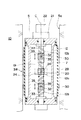
【図3】円孔の内周面の変位計測装置を示す縦断面正面図である。
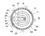
【図4】円孔の内周面の変位計測装置を図1のIV−IV線で切断した状態を示す平面図である。
【図5】回転方向変位の計測の原理を示す斜視図である。
【図6】半径方向変位の計測の原理を示す斜視図である。
【図7】軸方向変位の計測の原理を示す斜視図である。
【符号の説明】
1 変位計測装置
5a 内周面(円周面)
15 回転方向変位の計測手段
16 半径方向変位の計測手段
17 軸方向変位の計測手段
18 回転方向検出体
19 駆動軸(駆動部材)
20 回転方向検出器(半径方向検出器)
21 回転角計測器
29 計測部
30 軸方向検出体
31 変換器
32 軸方向検出器
38 半径方向検出体[0001]
BACKGROUND OF THE INVENTION
The present invention relates to a displacement measuring apparatus that measures displacement of a circumferential surface such as an inner circumferential surface of a circular hole or an outer circumferential surface of a cylinder. More specifically, the present invention relates to a displacement measuring device that measures the displacement of a circumferential surface separately for each component in the rotational direction, the radial direction, and the axial direction.
[0002]
[Prior art]
When measuring the displacement of an inner peripheral surface that is a cylindrical surface, such as an inner peripheral surface of a circular hole or pipe formed in the ground or rock, etc., the rotational direction, radial direction, and axial direction of the inner peripheral surface Displacement is measured separately for each component. Moreover, in the triaxial test of soil, rock, and concrete, the displacement of the outer peripheral surface of a cylinder is separately measured for every radial direction and axial direction. Furthermore, in the hollow torsion test of these soils, rocks, and concretes, displacements on the inner and outer peripheral surfaces of the cylinder are measured separately for each of the rotational direction (that is, the torsion direction), the radial direction, and the axial direction. In these cases, the rotational displacement, radial displacement, and axial displacement of the circumferential surface are measured as follows.
[0003]
In order to measure the rotational displacement of the circumferential surface, a rotational angle measuring instrument fixed at a position deviating from the circumferential surface is provided coaxially with the rotational center of the circumferential surface, and this rotational angle measuring instrument is mounted on the circumferential surface. Connect with one or more links. And if a circumferential surface rotates, a rotation angle measuring device will rotate via a link and a rotation angle can be measured. Alternatively, the rotational angle can be calculated from the known radius of the circumferential surface by measuring the movement displacement in the circumferential direction at one point fixed on the circumferential surface.
[0004]
There are the following methods for measuring the radial displacement of the circumferential surface. (1) Applying a strain gauge to the circumferential surface to measure the circumferential strain or measuring the change in the distance between two points fixed on the circumferential surface, Alternatively, the change in the circumferential length can be directly measured, and the radial displacement can be calculated based on the change in the circumferential length. {Circle around (2)} The measurement site is filled with an incompressible fluid so that it can flow in and out. Then, the inflow / outflow amount of fluid due to the displacement of the circumferential surface, that is, the volume and the axial length of the sealed space can be measured, and the radial displacement can be calculated based on these values. (3) A radial displacement can be obtained by directly measuring the diameter and radius of the circumferential surface.
[0005]
The axial displacement of the circumferential surface can be directly measured using a displacement measuring instrument capable of measuring the change in length.
[0006]
[Problems to be solved by the invention]
However, in the above-described method for measuring the displacement of the circumferential surface, a measuring instrument is provided for each of the three components of the displacement, so that the measurement work is complicated and the installation cost is increased. In addition, while measuring rotation direction displacement with a rotation angle measuring instrument, measuring axial displacement with a length displacement measuring instrument, each instrument is cumbersome and obtains measurement values with different dimensions. Therefore, the data analysis was complicated.
[0007]
SUMMARY OF THE INVENTION An object of the present invention is to provide a circumferential surface displacement measuring device that facilitates measurement work and data analysis and is inexpensive to install.
[0008]
[Means for Solving the Problems]
In order to achieve such an object, the circumferential surface displacement measuring apparatus according to
[0009]
Here, in this specification, the “circumferential surface” means a cylindrical surface whose cross section perpendicular to the center line is a perfect circle.
[0010]
Therefore, it is possible to measure the displacement of at least two components among the three components of the rotational direction, the radial direction, and the axial direction of the circumferential surface by using a common rotational angle measuring instrument. For this reason, since the displacement of a plurality of components can be measured by using a single rotation angle measuring instrument, the measurement work can be facilitated, the installation cost can be reduced, and the displacement measuring device can be downsized. Can do. In addition, measurement of rotational displacement and measurement of axial displacement can both be obtained using the rotational angle measurement results obtained by the rotational angle measuring instrument, which facilitates the verification of the measuring instrument and data. Can be easily analyzed.
[0011]
Claims1In the described circumferential surface displacement measuring device, the rotational direction displacement measuring means includes a rotational direction detector fixed on the circumferential surface, and, DrivingA rotation direction detector that rotates with the rotation of the moving member and detects a rotation direction detector is provided.
[0012]
Therefore, the rotation direction displacement can be obtained by using the value measured by the rotation angle measuring instrument as it is as shown in FIG.
[0013]
And claims1In the circumferential surface displacement measuring apparatus described above, the radial displacement measuring means is configured such that the radial detector is slidably installed on the circumferential surface and the distance along the rotational direction of the circumferential surface is constant. Two measuring units formed on the radial detector;, DrivingA radial detector that rotates with the rotation of the moving member and detects two measuring units is provided.
[0014]
Therefore, the radial displacement Δr can be calculated by
[0015]
<
Δr = r · (Δθ / θ) · (1- (Δθ / θ))
Where r: initial radius of the hole
Δr: radial displacement
θ: Initial angle on the side including the radial detector without circumferential deformation between the two measuring parts
Δθ: Displacement of θ
Claims1In the described circumferential surface displacement measuring apparatus, the axial displacement measuring means includes an axial direction detecting body fixed on the circumferential surface, and, DrivingA transducer that moves in the axial direction by rotation of the moving member, and a transducer attached to the transducer.DesperateAn axial direction detector that detects the axial direction detector and moves in the axial direction by the rotation of the moving member is provided.
[0016]
Therefore, the axial displacement can be calculated using the ratio of the rotation angle and the axial movement distance in the converter based on the value measured by the rotation angle measuring device as shown in FIG.
[0017]
DETAILED DESCRIPTION OF THE INVENTION
Hereinafter, the configuration of the present invention will be described in detail based on an example of an embodiment shown in the drawings. 1 to 7 show an embodiment of a circumferential surface
[0018]
The
[0019]
The
[0020]
The rotation direction displacement measuring means 15 includes a
[0021]
The
[0022]
The upper part of the
[0023]
The
[0024]
Further, as the
[0025]
Then, the
[0026]
The radial direction displacement measuring means 16 is formed in the radial
[0027]
The radial
[0028]
Here, the
[0029]
Then, as shown in FIG. 6, the
[0030]
Here, before detecting the displacement in the radial direction, the initial angle θ between the two measuring
[0031]
<
Δr = r · (Δθ / θ) · (1- (Δθ / θ))
Where r: initial radius of the hole
Δr: radial displacement
θ: Initial angle on the side including the radial detector without circumferential deformation between the two measuring parts
Δθ: Displacement of θ
Further, the axial displacement measuring means 17 includes an
[0032]
The axial
[0033]
The
[0034]
Furthermore, the
[0035]
Further, as the
[0036]
When measuring the displacement of the inner
[0037]
According to the
[0038]
The above-described embodiment is an example of a preferred embodiment of the present invention, but is not limited thereto, and various modifications can be made without departing from the scope of the present invention. exampleIfIn the present embodiment, the rotation direction detector and the radial direction detector are shared by one
[0039]
In the present embodiment, the
[0040]
Furthermore, in this embodiment, the
[0041]
Further, in the present embodiment, the rotation direction displacement measuring means 15 and the radial direction displacement measuring means 16 are provided one by one and the two axial displacement measuring means 17 are provided. It is sufficient that at least one means 15, 16, and 17 is provided, and two or more measuring means 15, 16, and 17 may be provided, for example. Thereby, even when there are a plurality of measurement locations, measurement can be performed by switching simultaneously or quickly. And even when there are a plurality of measurement points, the displacement for each component in the rotational direction, the radial direction, and the axial direction can be measured by the single rotation
[0042]
In the above-described embodiment, the
[0043]
In each of the above-described embodiments, the
[0044]
Alternatively, if the cylinder to be measured is hollow, the
[0045]
In the above-described embodiment, the
[0046]
Further, in each of the above-described embodiments, the measurement object of the
[0047]
【The invention's effect】
As is clear from the above description, according to the displacement measuring device for the inner circumferential surface of the circular hole according to
[0048]
Claims1According to the described circumferential surface displacement measuring apparatus, the rotational direction displacement measuring means includes a rotational direction detector fixed on the circumferential surface, and, DrivingSince it is provided with a rotation direction detector that rotates with the rotation of the moving member and detects the rotation direction detector, the value measured by the rotation angle measuring device is used as it is as shown in FIG. Can be obtained.
[0049]
And claims1According to the described circumferential surface displacement measuring device, the radial displacement measuring means has a constant distance along the rotational direction of the radial detector and the radial detector slidably installed on the circumferential surface. And two measuring parts formed on the radial detector, DrivingSince a radial detector that rotates with the rotation of the moving member and detects two measuring units is provided, the radial displacement Δr is a value θ measured by the rotational angle measuring device as shown in FIG. , Δθ can be calculated.
[0050]
Claims1According to the described circumferential surface displacement measuring device, the axial displacement measuring means includes an axial direction detecting body fixed on the circumferential surface and, DrivingA transducer that moves in the axial direction by rotation of the moving member, and a transducer attached to the transducer.DesperateSince it is provided with an axial direction detector that moves in the axial direction by the rotation of the moving member and detects the axial direction detection body, the axial displacement is based on the value measured by the rotational angle measuring instrument as shown in FIG. It can be calculated using the ratio of the rotation angle and the axial movement distance in the converter.
[Brief description of the drawings]
FIG. 1 is a longitudinal sectional side view showing an embodiment of a displacement measuring device for an inner peripheral surface of a circular hole of the present invention.
FIG. 2 is a longitudinal sectional front view showing an embodiment in which a displacement measuring device for an inner peripheral surface of a circular hole is used.
FIG. 3 is a longitudinal sectional front view showing a displacement measuring device for an inner peripheral surface of a circular hole.
4 is a plan view showing a state in which the displacement measuring device for the inner peripheral surface of the circular hole is cut along the line IV-IV in FIG. 1; FIG.
FIG. 5 is a perspective view showing the principle of measurement of rotational displacement.
FIG. 6 is a perspective view showing the principle of measurement of radial displacement.
FIG. 7 is a perspective view showing the principle of measurement of axial displacement.
[Explanation of symbols]
1 Displacement measuring device
5a Inner peripheral surface (circumferential surface)
15 Means for measuring rotational displacement
16 Measuring means for radial displacement
17 Measuring means for axial displacement
18 Rotation direction detector
19 Drive shaft(WDMoving partMaterial)
20 Rotation direction detector (radial direction detector)
21 Rotation angle measuring instrument
29 Measurement unit
30 Axial direction detector
31 Converter
32 Axial direction detector
38 Radial direction detector
Claims (1)
Priority Applications (1)
| Application Number | Priority Date | Filing Date | Title |
|---|---|---|---|
| JP18299498A JP4046855B2 (en) | 1998-06-29 | 1998-06-29 | Circumferential displacement measuring device |
Applications Claiming Priority (1)
| Application Number | Priority Date | Filing Date | Title |
|---|---|---|---|
| JP18299498A JP4046855B2 (en) | 1998-06-29 | 1998-06-29 | Circumferential displacement measuring device |
Publications (2)
| Publication Number | Publication Date |
|---|---|
| JP2000018943A JP2000018943A (en) | 2000-01-21 |
| JP4046855B2 true JP4046855B2 (en) | 2008-02-13 |
Family
ID=16127905
Family Applications (1)
| Application Number | Title | Priority Date | Filing Date |
|---|---|---|---|
| JP18299498A Expired - Fee Related JP4046855B2 (en) | 1998-06-29 | 1998-06-29 | Circumferential displacement measuring device |
Country Status (1)
| Country | Link |
|---|---|
| JP (1) | JP4046855B2 (en) |
Families Citing this family (4)
| Publication number | Priority date | Publication date | Assignee | Title |
|---|---|---|---|---|
| JP5337004B2 (en) * | 2009-11-19 | 2013-11-06 | 一般財団法人電力中央研究所 | In-situ rock tension test method and test apparatus |
| JP4772159B1 (en) * | 2010-08-05 | 2011-09-14 | 株式会社フレスコーヴォ | Ground improvement machine |
| JP6220257B2 (en) * | 2013-12-17 | 2017-10-25 | 三菱重工業株式会社 | Pipe life evaluation method |
| CN116518835B (en) * | 2023-07-03 | 2023-08-25 | 太原市水利勘测设计院 | Water conservancy pipeline facilities deformation check out test set |
-
1998
- 1998-06-29 JP JP18299498A patent/JP4046855B2/en not_active Expired - Fee Related
Also Published As
| Publication number | Publication date |
|---|---|
| JP2000018943A (en) | 2000-01-21 |
Similar Documents
| Publication | Publication Date | Title |
|---|---|---|
| US5142906A (en) | Apparatus for measuring valve stem loads in a motor operated valve assembly | |
| CA2604819C (en) | Method of applying a strain sensor to a cylindrical structure | |
| US6386043B1 (en) | Lateral motion sensing assembly | |
| US6600310B2 (en) | Linear and rotary magnetic sensor | |
| CA2428551A1 (en) | Apparatus for measuring shape of pipeline and therefor | |
| JP4046855B2 (en) | Circumferential displacement measuring device | |
| JPS61226606A (en) | Device for measuring roundness deviation of eccentric support surface | |
| US12540808B2 (en) | Internal inspection device for determining a length of a tubular good | |
| JPS61129544A (en) | Method and device for measuring hydraulic and pneumatic pressure of sealed bore hole | |
| JPH04262216A (en) | Device for measuring axial loads applied to cylindrical members | |
| CN109373886A (en) | Detection device based on scale topography variation | |
| ES2369484T3 (en) | DEVICE FOR MEASURING THE REAL LENGTH OF AN ELECTROMECHANICAL LINEAR DRIVE. | |
| JP5156860B2 (en) | Shield machine | |
| JP2003014427A (en) | Measuring apparatus and measuring method for axial distortion and lateral distortion of cylindrical specimen | |
| US6442862B1 (en) | Displacement measuring apparatus | |
| US8359935B2 (en) | Fiber optic rotation/position sensor | |
| KR100694201B1 (en) | Torque sensor and electric power assist steering device of automobile | |
| US5402682A (en) | Rotor of an ultrasonic test device for rotationally symmetrical test specimens, especially tubes | |
| US9021855B2 (en) | Torsional flow sensor | |
| KR102853926B1 (en) | Durability test device for remote control valves | |
| CN116261647A (en) | Linear displacement transducer | |
| RU2065590C1 (en) | Sandy soil pressure transducer | |
| RU2377406C1 (en) | Deformometre | |
| RU2205919C2 (en) | Gear measuring direction and velocity of ground movement relative to underground pipe-line and loads on pipe-line caused by ground movement | |
| RU2142560C1 (en) | Sensor of deflecting tool position, azimuth and zenith angles of well |
Legal Events
| Date | Code | Title | Description |
|---|---|---|---|
| A621 | Written request for application examination |
Free format text: JAPANESE INTERMEDIATE CODE: A621 Effective date: 20050603 |
|
| A977 | Report on retrieval |
Free format text: JAPANESE INTERMEDIATE CODE: A971007 Effective date: 20070403 |
|
| A131 | Notification of reasons for refusal |
Free format text: JAPANESE INTERMEDIATE CODE: A131 Effective date: 20070808 |
|
| A521 | Written amendment |
Free format text: JAPANESE INTERMEDIATE CODE: A523 Effective date: 20071005 |
|
| TRDD | Decision of grant or rejection written | ||
| A01 | Written decision to grant a patent or to grant a registration (utility model) |
Free format text: JAPANESE INTERMEDIATE CODE: A01 Effective date: 20071031 |
|
| A61 | First payment of annual fees (during grant procedure) |
Free format text: JAPANESE INTERMEDIATE CODE: A61 Effective date: 20071121 |
|
| FPAY | Renewal fee payment (event date is renewal date of database) |
Free format text: PAYMENT UNTIL: 20101130 Year of fee payment: 3 |
|
| R150 | Certificate of patent or registration of utility model |
Free format text: JAPANESE INTERMEDIATE CODE: R150 |
|
| FPAY | Renewal fee payment (event date is renewal date of database) |
Free format text: PAYMENT UNTIL: 20111130 Year of fee payment: 4 |
|
| FPAY | Renewal fee payment (event date is renewal date of database) |
Free format text: PAYMENT UNTIL: 20121130 Year of fee payment: 5 |
|
| FPAY | Renewal fee payment (event date is renewal date of database) |
Free format text: PAYMENT UNTIL: 20131130 Year of fee payment: 6 |
|
| LAPS | Cancellation because of no payment of annual fees |