JP4052425B2 - Biologically treated water and odor gas treatment method - Google Patents
Biologically treated water and odor gas treatment method Download PDFInfo
- Publication number
- JP4052425B2 JP4052425B2 JP2001252620A JP2001252620A JP4052425B2 JP 4052425 B2 JP4052425 B2 JP 4052425B2 JP 2001252620 A JP2001252620 A JP 2001252620A JP 2001252620 A JP2001252620 A JP 2001252620A JP 4052425 B2 JP4052425 B2 JP 4052425B2
- Authority
- JP
- Japan
- Prior art keywords
- gas
- liquid
- treated water
- treated
- processed
- Prior art date
- Legal status (The legal status is an assumption and is not a legal conclusion. Google has not performed a legal analysis and makes no representation as to the accuracy of the status listed.)
- Expired - Fee Related
Links
- XLYOFNOQVPJJNP-UHFFFAOYSA-N water Substances O XLYOFNOQVPJJNP-UHFFFAOYSA-N 0.000 title claims description 27
- 238000000034 method Methods 0.000 title description 13
- 239000007789 gas Substances 0.000 claims description 61
- 238000006243 chemical reaction Methods 0.000 claims description 24
- LSDPWZHWYPCBBB-UHFFFAOYSA-N Methanethiol Chemical compound SC LSDPWZHWYPCBBB-UHFFFAOYSA-N 0.000 claims description 14
- WQOXQRCZOLPYPM-UHFFFAOYSA-N dimethyl disulfide Chemical compound CSSC WQOXQRCZOLPYPM-UHFFFAOYSA-N 0.000 claims description 12
- 239000000126 substance Substances 0.000 claims description 11
- RWSOTUBLDIXVET-UHFFFAOYSA-N Dihydrogen sulfide Chemical compound S RWSOTUBLDIXVET-UHFFFAOYSA-N 0.000 claims description 8
- 238000005273 aeration Methods 0.000 claims description 8
- 229910000037 hydrogen sulfide Inorganic materials 0.000 claims description 8
- 238000003672 processing method Methods 0.000 claims description 8
- QMMFVYPAHWMCMS-UHFFFAOYSA-N Dimethyl sulfide Chemical compound CSC QMMFVYPAHWMCMS-UHFFFAOYSA-N 0.000 claims description 7
- 230000001678 irradiating effect Effects 0.000 claims description 4
- BWGNESOTFCXPMA-UHFFFAOYSA-N Dihydrogen disulfide Chemical compound SS BWGNESOTFCXPMA-UHFFFAOYSA-N 0.000 claims 1
- 125000002496 methyl group Chemical group [H]C([H])([H])* 0.000 claims 1
- 239000007788 liquid Substances 0.000 description 76
- 241000894006 Bacteria Species 0.000 description 13
- 230000000694 effects Effects 0.000 description 8
- 238000010586 diagram Methods 0.000 description 6
- 238000004140 cleaning Methods 0.000 description 5
- QSHDDOUJBYECFT-UHFFFAOYSA-N mercury Chemical compound [Hg] QSHDDOUJBYECFT-UHFFFAOYSA-N 0.000 description 5
- 229910052753 mercury Inorganic materials 0.000 description 5
- 230000001681 protective effect Effects 0.000 description 5
- 238000004659 sterilization and disinfection Methods 0.000 description 5
- 241000588724 Escherichia coli Species 0.000 description 3
- OKKJLVBELUTLKV-UHFFFAOYSA-N Methanol Chemical compound OC OKKJLVBELUTLKV-UHFFFAOYSA-N 0.000 description 3
- 239000000383 hazardous chemical Substances 0.000 description 3
- 239000010842 industrial wastewater Substances 0.000 description 3
- 239000003621 irrigation water Substances 0.000 description 3
- 239000010453 quartz Substances 0.000 description 3
- 239000010865 sewage Substances 0.000 description 3
- VYPSYNLAJGMNEJ-UHFFFAOYSA-N silicon dioxide Inorganic materials O=[Si]=O VYPSYNLAJGMNEJ-UHFFFAOYSA-N 0.000 description 3
- 230000001954 sterilising effect Effects 0.000 description 3
- 239000002699 waste material Substances 0.000 description 3
- 238000004065 wastewater treatment Methods 0.000 description 3
- QJZYHAIUNVAGQP-UHFFFAOYSA-N 3-nitrobicyclo[2.2.1]hept-5-ene-2,3-dicarboxylic acid Chemical compound C1C2C=CC1C(C(=O)O)C2(C(O)=O)[N+]([O-])=O QJZYHAIUNVAGQP-UHFFFAOYSA-N 0.000 description 2
- QGZKDVFQNNGYKY-UHFFFAOYSA-N Ammonia Chemical compound N QGZKDVFQNNGYKY-UHFFFAOYSA-N 0.000 description 2
- XSTXAVWGXDQKEL-UHFFFAOYSA-N Trichloroethylene Chemical group ClC=C(Cl)Cl XSTXAVWGXDQKEL-UHFFFAOYSA-N 0.000 description 2
- IISBACLAFKSPIT-UHFFFAOYSA-N bisphenol A Chemical compound C=1C=C(O)C=CC=1C(C)(C)C1=CC=C(O)C=C1 IISBACLAFKSPIT-UHFFFAOYSA-N 0.000 description 2
- 239000000356 contaminant Substances 0.000 description 2
- 239000003651 drinking water Substances 0.000 description 2
- 235000020188 drinking water Nutrition 0.000 description 2
- 239000010871 livestock manure Substances 0.000 description 2
- 239000010802 sludge Substances 0.000 description 2
- 239000007921 spray Substances 0.000 description 2
- 229910021642 ultra pure water Inorganic materials 0.000 description 2
- 239000012498 ultrapure water Substances 0.000 description 2
- BJQHLKABXJIVAM-BGYRXZFFSA-N 1-o-[(2r)-2-ethylhexyl] 2-o-[(2s)-2-ethylhexyl] benzene-1,2-dicarboxylate Chemical compound CCCC[C@H](CC)COC(=O)C1=CC=CC=C1C(=O)OC[C@H](CC)CCCC BJQHLKABXJIVAM-BGYRXZFFSA-N 0.000 description 1
- ISPYQTSUDJAMAB-UHFFFAOYSA-N 2-chlorophenol Chemical compound OC1=CC=CC=C1Cl ISPYQTSUDJAMAB-UHFFFAOYSA-N 0.000 description 1
- BJQHLKABXJIVAM-UHFFFAOYSA-N Diethylhexyl phthalate Natural products CCCCC(CC)COC(=O)C1=CC=CC=C1C(=O)OCC(CC)CCCC BJQHLKABXJIVAM-UHFFFAOYSA-N 0.000 description 1
- IGFHQQFPSIBGKE-UHFFFAOYSA-N Nonylphenol Natural products CCCCCCCCCC1=CC=C(O)C=C1 IGFHQQFPSIBGKE-UHFFFAOYSA-N 0.000 description 1
- INPDFIMLLXXDOQ-UHFFFAOYSA-N Phycocyanobilin Natural products CCC1=C(C)C(=CC2=NC(=C/c3[nH]c(C=C/4C(C(C(N4)=O)C)=CC)c(C)c3CCC(=O)O)C(=C2C)CCC(=O)O)NC1=O INPDFIMLLXXDOQ-UHFFFAOYSA-N 0.000 description 1
- 230000002378 acidificating effect Effects 0.000 description 1
- 239000003905 agrochemical Substances 0.000 description 1
- 229910021529 ammonia Inorganic materials 0.000 description 1
- 230000000711 cancerogenic effect Effects 0.000 description 1
- 231100000315 carcinogenic Toxicity 0.000 description 1
- 238000011109 contamination Methods 0.000 description 1
- 238000000354 decomposition reaction Methods 0.000 description 1
- 230000007423 decrease Effects 0.000 description 1
- 238000004332 deodorization Methods 0.000 description 1
- 238000010612 desalination reaction Methods 0.000 description 1
- 238000001784 detoxification Methods 0.000 description 1
- 150000002013 dioxins Chemical class 0.000 description 1
- 238000010494 dissociation reaction Methods 0.000 description 1
- 230000005593 dissociations Effects 0.000 description 1
- 230000007613 environmental effect Effects 0.000 description 1
- 230000005284 excitation Effects 0.000 description 1
- 210000003608 fece Anatomy 0.000 description 1
- 239000005556 hormone Substances 0.000 description 1
- 229940088597 hormone Drugs 0.000 description 1
- 239000004021 humic acid Substances 0.000 description 1
- 238000009434 installation Methods 0.000 description 1
- SNQQPOLDUKLAAF-UHFFFAOYSA-N nonylphenol Chemical compound CCCCCCCCCC1=CC=CC=C1O SNQQPOLDUKLAAF-UHFFFAOYSA-N 0.000 description 1
- 230000003287 optical effect Effects 0.000 description 1
- 150000004045 organic chlorine compounds Chemical class 0.000 description 1
- 239000007800 oxidant agent Substances 0.000 description 1
- CEOCDNVZRAIOQZ-UHFFFAOYSA-N pentachlorobenzene Chemical compound ClC1=CC(Cl)=C(Cl)C(Cl)=C1Cl CEOCDNVZRAIOQZ-UHFFFAOYSA-N 0.000 description 1
- 231100000614 poison Toxicity 0.000 description 1
- 239000008213 purified water Substances 0.000 description 1
- 239000007787 solid Substances 0.000 description 1
- 239000013076 target substance Substances 0.000 description 1
- 239000010409 thin film Substances 0.000 description 1
- 239000003440 toxic substance Substances 0.000 description 1
- 238000009423 ventilation Methods 0.000 description 1
- 238000013022 venting Methods 0.000 description 1
Images


Landscapes
- Physical Water Treatments (AREA)
- Physical Or Chemical Processes And Apparatus (AREA)
- Treating Waste Gases (AREA)
Description
【0001】
【発明の属する技術分野】
本発明は、液体及び気体の同時光処理に係り、特に、最終処分場の浸出水、産業廃水、下水、屎尿、家畜糞尿、用水、上水、飲料水、純水、超純水、等の水処理施設、汚泥処理施設又は造水施設、有害物質処理施設、廃棄物処理施設などにおいて、生物処理水及び臭気ガスを対象として、紫外線により同時処理する方法と装置に関するものである。
【0002】
【従来の技術】
液体に対する光処理では、特に紫外線処理が(1)有機物分解、(2)有機物又は酸化剤の分子結合の励起/解離、(3)殺菌・消毒などの目的で広く用いられている。液体に対する紫外線照射方法としては、液体の槽に紫外線ランプ及び紫外線ランプを保護する保護管を浸せきさせた状態で紫外線を照射する方法、又は、垂直に立てた円筒又は平面状の壁に沿って水を薄膜状に流下させ、外部から気体を介して紫外線を照射する方法が行われていた。
気体に対する光処理においても、液体に対する場合と同様に、除害及び脱臭などの目的で紫外線処理などが用いられている。
水処理施設、汚泥処理施設、有害物質処理施設、廃棄物処理施設などでは、上記のような目的で紫外線処理を必要とする液体及び気体が発生する場合があるが、これらは別々の紫外線処理装置で処理され、複数の紫外線処理装置が必要で装置コストが高額となる欠点があった。
また、紫外線処理装置では、照射後の生成物などが光源に付着し、その汚染によって照射効率が低下するため、頻繁に洗浄が必要となる場合がある。
【0003】
【発明が解決しようとする課題】
本発明は、上記従来技術に鑑み、生物処理水及び臭気ガスを対象として、同一の装置で同時に紫外線処理し、さらに洗浄頻度を低減あるいはその必要性が無くなる同時紫外線処理方法を提供することを課題とする。
【0004】
【課題を解決するための手段】
上記課題を解決するために、本発明では、内部に紫外線ランプを有する反応槽に生物処理水を導入して、紫外線ランプを浸せきさせた状態で紫外線を照射し、同時に該反応槽にばっ気によって硫化水素、メチルメルカプタン、硫化メチル、二硫化メチルを含む臭気ガスを導入して、前記生物処理水及びガス中に含有する処理対象物質を処理するか、又は、内部に紫外線ランプを有する反応槽に、紫外線を照射しながら該紫外線ランプの周囲に生物処理水を散布し、同時に該反応槽に硫化水素、メチルメルカプタン、硫化メチル、二硫化メチルを含む臭気ガスを導入して、前記生物処理水及びガス中に含有する処理対象物質を処理する生物処理水及び臭気ガスの処理方法としたものである。
【0005】
【発明の実施の形態】
本発明では、反応槽に被処理液体を注入し、光源を浸せきさせた状態で光を照射する。このとき、ばっ気によって被処理ガスを反応槽内に導入して光を照射する。
紫外線などの光は、紫外線ランプなどの光源により、被処理液体に照射される。このとき、被処理ガスを光源表面に接触するようにばっ気によって供給する。このような構成にすることにより、光源から発せられた光は液体及び気体双方に同時に照射される。よって、気体及び液体を同一光源により同時に光処理することができる。
また、本発明では、反応槽内に光源を設置し、散水ノズルなどを通じて被処理液体を光源に向かって散布すると同時に、被処理ガスを該反応槽に通気する。このような構成にすることにより、光源から発せられた光は液体及び気体双方に同時に照射される。よって、気体及び液体を同一光源により同時に光処理することができる。
【0006】
さらに、被処理液体と被処理ガスが接触することにより、被処理ガス中の液に吸収され得る成分が被処理液中に吸収される。すなわち、被処理液体による被処理ガスに対する洗浄効果が期待できる。水に吸収され得る成分を具体的に挙げると、アンモニア、メタノール、硫化水素などがあるが、これらに限定されない。
光源は、紫外線を供給する場合では、低圧水銀ランプ、中圧水銀ランプ、高圧水銀ランプ、エキシマレーザー、ブラックライト等、170〜380nmの範囲の紫外線を照射可能なものを挙げることができる。紫外線ランプの破損防止のために保護管を使用する場合、普通石英(天然石英)、合成石英を用いるのが良い。
光源の長手方向、被処理液体の流れ方向、被処理気体の流れ方向は、それぞれ地面に対して垂直、水平、斜方など、任意に選定することができる。被処理液体の流れ方向及び被処理気体の流れ方向は、上昇流、下降流のいずれであっても良い。また、互いの流れは、並流、向流、ねじれの関係のいずれであっても良い。
光源の間隔、流速は、液体及び気体の種類、処理量、又は所望の処理性能などにより任意に選定することができる。
【0007】
本発明による照射方法の被処理液体としては、(1)最終処分場の浸出水、産業廃水、用水、下水、有害物質処理施設、廃棄物処理施設などで発生する汚水、(2)上水、浄水、飲料水、純水、超純水、等の液体、有機物、又は細菌、原虫などの生物を含む液体、などが挙げられるが、これに限るものではない。
液体中の処理対象物質としては、(1)フミン酸などの生物難分解性有機物、(2)ダイオキシン類、コプラナPCB、ビスフェノールA、ノニルフェノール、フタル酸ジエチルヘキシルなどの環境ホルモン類又は発ガン性物質、(3)トリクロロエチレン、クロロフェノール、農薬、TOXなどの有機塩素化合物、(4)大腸菌、一般細菌、クリプトスポルジウムなどの細菌・原虫、(5)色度、臭気成分などを挙げることができるが、これに限るものではない。
【0008】
本発明による照射方法の被処理ガスとしては、最終処分場の浸出水、産業廃水、用水、下水、有害物質処理施設、廃棄物処理施設などで発生する悪臭や有害成分を含むガスなどが挙げられるが、これに限るものではない。
気体中の処理対象物質としては、(1)臭気成分(2)トリクロロエチレン、TOXなどの有害物質、(3)大腸菌、一般細菌などの細菌などを挙げることができるが、これに限るものではない。
本発明における処理条件は、被処理液体の通液量、被処理ガスの通気量、紫外線ランプの強度及び寸法、内壁の形状等により任意に選定することができる。
【0009】
次に、本発明を図面により説明する。
図1〜図3は、本発明の光源を被処理液体中に浸せきする形式の装置の概略構成図であり、図4及び図5は、光源に被処理液体を散布する形式の装置の概略構成図である。
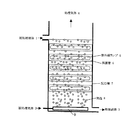
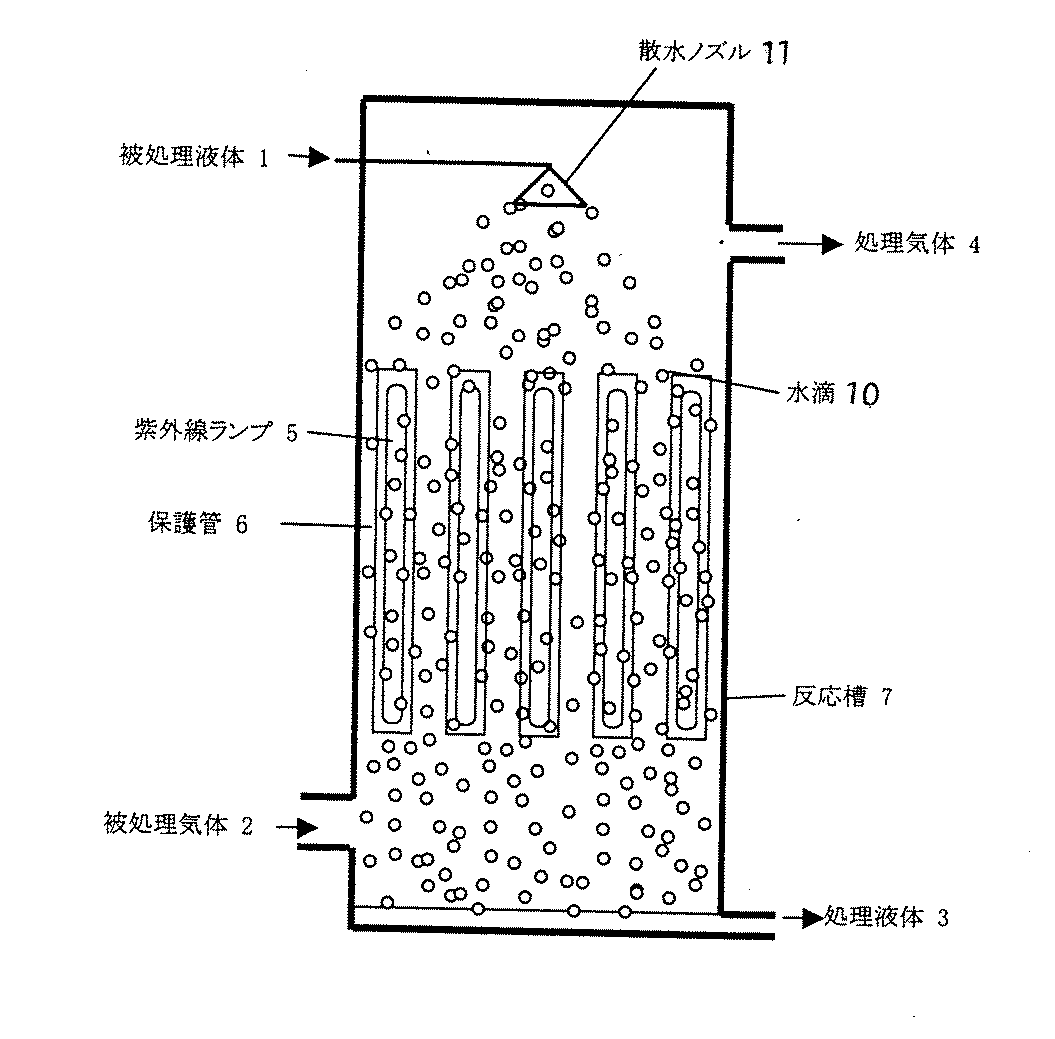
図において、1は被処理液体、2は被処理ガス、3は処理液体、4は処理ガス、5は紫外線ランプ、6は保護管、7は反応槽、8は気泡、9は散気筒、10は水滴、11は散布ノズルである。
図1では、反応槽7は、紫外線ランプ5の長手方向を地面に対して平行とし、被処理液体1中に浸せきされており、処理ガス2及び被処理液体1の流れ方向が、地面に対して垂直であり、被処理ガス2が上昇流、被処理液体1が下降流の場合の例である。被処理液体1は反応槽7の上部から注入させ、底部から排出される。被処理ガス2は、反応槽7底部の散気筒9から供給し、光源表面付近を上昇し、上部から排出される。
【0010】
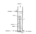
図2では、紫外線ランプ5の長手方向と被処理ガス2及び被処理液体1の流れ方向がいずれも地面に対して垂直で、被処理ガス2と被処理液体1が平行流となっている。このような構成においても、本発明の効果に変りはない。
また、図3では、紫外線ランプ5の長手方向と被処理ガス2及び被処理液体1の流れ方向がいずれも地面に対して垂直で、被処理ガス2と被処理液体1が平行流となっている。このような構成においても本発明の効果に変りはない。
また、図3では、紫外線ランプ5の長手方向と被処理ガス2及び被処理液体1の流れ方向がいずれも地面に対して垂直で、被処理ガス2と被処理液体1が対向流れとなっている。このような構成においても、本発明の効果に変りはない。
【0011】
図4では、反応槽7は、紫外線ランプ5の長手方向と被処理ガス2及び被処理液体1の流れ方向がいずれも地面に対して垂直であり、被処理ガス2が上昇流、被処理液体1が下降流の場合の例である。被処理液体1は、反応槽7の上部から散水ノズル11で散水され、保護管6表面や間の空間を通過して、紫外線を照射され、底部から排出される。被処理ガス2は、反応槽7底部から供給され、光源間の空間を通過して紫外線を照射され、上部から排出される。
図5では、図4の形式において、被処理ガス2の流れ方向と被処理液体1の流れ方向が並流となっている。このような構成においても、本発明の効果に変りはない。
【0012】
【実施例】
以下に、本発明の具体的実施例を説明するが、本発明はこれに限定されるものではない。
実施例1
図1に示す装置を用いて、農業集落排水処理施設の処理過程で発生する液体及び気体を処理した。液体及び気体の種類・性状及び処理条件を下記に示す。
液体
生物処理水(殺菌処理前)
一般細菌数:100000個/mL
大腸菌群数:500個/mL
【0013】
紫外線ランプ:低圧水銀ランプ(合計入力電力250W)
通液量:10L/min
通気量:0.2m3/min
上記のような条件で、被処理液体を装置上部から流入させ、底部から流出させた。被処理ガスは、底部の散気筒から流入させた。
また、対照系として、装置に被処理気体をばっ気せず、被処理液体のみを流入させた。
【0014】
処理した結果を下記に示す。なお、6ヶ月間連続照射後の結果である。
処理結果
液体(処理後)
処理液体の一般細菌数:300個/mL(除去率99.7%)
処理液体の大腸菌群数:<5個/mL(除去率99.5%以上)
処理液体の一般細菌数:4000個/mL(除去率96%)
処理液体の大腸菌群数:2個/mL(除去率99.6%)
【0015】
以上より、液体では一般細菌除去率99.7%、大腸菌群数除去率99.5%以上、気体では悪臭物質である硫化水素除去率97.5%以上、メチルメルカプタン除去率98.5%以上、硫化メチル除去率75.5%以上、二硫化メチル除去率87%以上が得られることが確認された。
よって、本発明による方法では、同一の処理装置で、液体及び気体を同時に光処理できることが確認された。
一方、液体のみを注入した対照では、処理液体の一般細菌数除去率96%、大腸菌群数除去率99.6%と低く、紫外線照射装置の表面に付着物が認められ、これらにより紫外線が遮られたものと考えられた。
よって、本発明の方法では、紫外線照射装置の表面の汚染物質が被処理ガスのばっ気による洗浄効果で除去されたことが分かった。
【0016】
実施例2
図4に示す装置を用いて、農業集落排水処理施設の処理過程で発生する液体及び気体を処理した。液体及び気体の種類・性状及び処理条件を下記に示す。
液体
生物処理水(殺菌処理前)
一般細菌数:100,000個/mL
大腸菌群数:500個/mL
処理条件
紫外線ランプ:低圧水銀ランプ(合計入力電力250W)
通液量:10L/min
通気量:2m3/min
上記のような条件で被処理液体を装置上部から散水し、底部から流出させた。被処理ガスは底部から流入させた。
また、対照系として、装置に被処理液体を注入せず、被処理気体のみを通気させた。
処理した結果を下記に示す。なお、6ヶ月間連続照射後の結果である。
【0018】
処理結果
液体(処理後)
処理液体の一般細菌数:300(除去率99.7%)
処理液体の大腸菌群数:<5個/mL(除去率99.5%以上)
以上より、液体では一般細菌除去率99.7%、大腸菌群数除去率99.5%以上、気体では悪臭物質である硫化水素除去率97.5%以上、メチルメルカプタン除去率98.5%以上、硫化メチル除去率75.5%以上、二硫化メチル除去率87%以上が得られることが確認された。
よって、本発による方法では、同一の処理装置で液体及び気体を同時に処理できることが確認された。
一方、気体のみを通気した場合、硫化水素除去率87.5%、メチルメルカプタン除去率94.5%、硫化メチル除去率70%、二硫化メチル除去率80%と低く、紫外線照射装置の表面に酸性の液体状及び白色の固体状の付着物が認められ、これらにより紫外線が遮られたものと考えられた。
よって、本発明の方法では紫外線照射装置の表面の汚染物質が被処理液体による洗浄効果で除去されたことが分かった。
【0020】
【発明の効果】
本発明による液体及び気体の同時光処理方法を用いることにより、液体及び
気体を同一の装置で光処理することができる。
つまり、反応槽に被処理液体を注入し、光源を浸せきさせて光を照射し、同時にばっ気によって被処理ガスを反応槽に供給するか、反応槽に被処理液体を光源に向かって散水して光を照射し、同時に被処理ガスを反応槽に通気することにより、液体及び気体が同一光源で光処理される。
同一光源及び装置で処理できることにより、これまで液体及び気体それぞれに必要であった処理装置を同一とすることができ、装置費用及びランニングコストの低減、設置面積の低減が可能となる。
【図面の簡単な説明】
【図1】本発明の処理方法に用いる装置の一例を示す概略構成図。
【図2】本発明の処理方法に用いる装置の他の例を示す概略構成図。
【図3】本発明の処理方法に用いる装置の他の例を示す概略構成図。
【図4】本発明の処理方法に用いる装置の別の例を示す概略構成図。
【図5】本発明の処理方法に用いる装置の別の例を示す概略構成図。
【符号の説明】
1:被処理液体、2:被処理ガス、3:処理液体、4:処理ガス、5:紫外線ランプ、6:保護管、7:反応槽、8:気泡、9:散気筒、10:水滴、11:散水ノズル[0001]
BACKGROUND OF THE INVENTION
The present invention relates to simultaneous optical treatment of liquid and gas, and in particular, leachate of final disposal site, industrial wastewater, sewage, manure, livestock manure, irrigation water, drinking water, pure water, ultrapure water, etc. water treatment facilities, sludge treatment facilities or desalination facilities, toxic substances treatment facilities, such as in waste treatment facilities, as a target the biologically treated water and odorous gas, to an apparatus and method for more simultaneous processing to ultraviolet rays.
[0002]
[Prior art]
In the light treatment for liquids, in particular, ultraviolet treatment is widely used for purposes such as (1) decomposition of organic substances, (2) excitation / dissociation of molecular bonds of organic substances or oxidizing agents, and (3) sterilization / disinfection. As a method of irradiating the liquid with ultraviolet rays, the ultraviolet ray and a protective tube for protecting the ultraviolet lamp are immersed in a liquid tank, or ultraviolet rays are irradiated, or water is laid along a vertically standing cylinder or plane wall. Has been carried out in a thin film and irradiated with ultraviolet rays from the outside through a gas.
In light treatment for gas, as in the case of liquid, ultraviolet treatment or the like is used for the purpose of detoxification and deodorization.
In water treatment facilities, sludge treatment facilities, hazardous substance treatment facilities, waste treatment facilities, etc., liquids and gases that require ultraviolet treatment may be generated for the above purposes, but these are separate ultraviolet treatment devices. In other words, a plurality of ultraviolet ray processing apparatuses are necessary, and the apparatus cost is high.
In addition, in the ultraviolet treatment apparatus, the product after irradiation adheres to the light source, and the irradiation efficiency decreases due to the contamination, so that cleaning may be frequently required.
[0003]
[Problems to be solved by the invention]
In view of the above prior art, as a target the biologically treated water and odorous gases, that ultraviolet treated simultaneously in the same device, further provides reduced or simultaneous disinfection how that need is eliminated for the cleaning frequency Let it be an issue.
[0004]
[Means for Solving the Problems]
In order to solve the above problems, in the present invention, biological treatment water is introduced into a reaction vessel having an ultraviolet lamp inside, and ultraviolet rays are irradiated in a state where the ultraviolet lamp is immersed, and at the same time, the reaction vessel is aerated by aeration. An odor gas containing hydrogen sulfide, methyl mercaptan, methyl sulfide, or methyl disulfide is introduced to treat the biologically treated water and the substance to be treated contained in the gas , or in a reaction tank having an ultraviolet lamp inside. UV sparged with biologically treated water around the UV lamp while irradiating the hydrogen sulfide in the reaction vessel at the same time, methyl mercaptan, methyl sulfide, by introducing an odor gas including methyl disulfide, the biologically treated water and it is obtained by the processing method of the biologically treated water and odor gas handling process target substance contained in the gas.
[0005]
DETAILED DESCRIPTION OF THE INVENTION
In the present invention, the liquid to be treated is injected into the reaction vessel, and light is irradiated in a state where the light source is immersed. At this time, the gas to be treated is introduced into the reaction tank by aeration and irradiated with light.
The liquid to be processed is irradiated with light such as ultraviolet rays by a light source such as an ultraviolet lamp. At this time, the gas to be treated is supplied by aeration so as to come into contact with the surface of the light source. With such a configuration, the light emitted from the light source is simultaneously applied to both the liquid and the gas. Therefore, the gas and the liquid can be simultaneously optically processed by the same light source.
In the present invention, a light source is installed in the reaction tank, and the liquid to be processed is sprayed toward the light source through a watering nozzle or the like, and simultaneously, the gas to be processed is vented to the reaction tank. With such a configuration, the light emitted from the light source is simultaneously applied to both the liquid and the gas. Therefore, the gas and the liquid can be simultaneously optically processed by the same light source.
[0006]
Furthermore, when the liquid to be processed and the gas to be processed come into contact with each other, components that can be absorbed by the liquid in the gas to be processed are absorbed into the liquid to be processed. That is, a cleaning effect on the gas to be processed by the liquid to be processed can be expected. Specific examples of components that can be absorbed by water include, but are not limited to, ammonia, methanol, hydrogen sulfide, and the like.
In the case of supplying ultraviolet light, examples of the light source include a low pressure mercury lamp, a medium pressure mercury lamp, a high pressure mercury lamp, an excimer laser, and a black light that can irradiate ultraviolet light in the range of 170 to 380 nm. When using a protective tube to prevent damage to the ultraviolet lamp, it is preferable to use ordinary quartz (natural quartz) or synthetic quartz.
The longitudinal direction of the light source, the flow direction of the liquid to be processed, and the flow direction of the gas to be processed can be arbitrarily selected such as vertical, horizontal, and oblique to the ground. The flow direction of the liquid to be processed and the flow direction of the gas to be processed may be either an upward flow or a downward flow. Further, the mutual flow may be any of a parallel flow, a counter flow, and a twist relationship.
The interval between the light sources and the flow velocity can be arbitrarily selected according to the type of liquid and gas, the processing amount, or the desired processing performance.
[0007]
Liquids to be treated by the irradiation method according to the present invention include (1) leachate at the final disposal site, industrial wastewater, irrigation water, sewage, hazardous substance treatment facility, wastewater treatment facility, etc., (2) clean water, Examples include, but are not limited to, liquids such as purified water, drinking water, pure water, and ultrapure water, organic substances, and liquids containing organisms such as bacteria and protozoa.
Substances to be treated in liquids include (1) refractory organic substances such as humic acid, (2) environmental hormones such as dioxins, coplana PCB, bisphenol A, nonylphenol, diethylhexyl phthalate, or carcinogenic substances. (3) Organochlorine compounds such as trichlorethylene, chlorophenol, agricultural chemicals, TOX, (4) bacteria and protozoa such as Escherichia coli, general bacteria, cryptospordium, (5) chromaticity, odor components, etc. However, it is not limited to this.
[0008]
Examples of the gas to be treated by the irradiation method according to the present invention include leachate at the final disposal site, industrial waste water, irrigation water, sewage, hazardous substance treatment facility, waste treatment facility, and other gases containing malodors and harmful components. However, it is not limited to this.
Examples of substances to be treated in the gas include (1) odorous components, (2) harmful substances such as trichlorethylene and TOX, and (3) bacteria such as Escherichia coli and general bacteria, but are not limited thereto.
The treatment conditions in the present invention can be arbitrarily selected depending on the amount of liquid to be treated, the amount of gas to be treated, the intensity and size of the ultraviolet lamp, the shape of the inner wall, and the like.
[0009]
Next, the present invention will be described with reference to the drawings.
1 to 3 are schematic configuration diagrams of an apparatus of the type in which the light source of the present invention is immersed in a liquid to be processed, and FIGS. FIG.
In the figure, 1 is a liquid to be treated, 2 is a gas to be treated, 3 is a treatment liquid, 4 is a treatment gas, 5 is an ultraviolet lamp, 6 is a protective tube, 7 is a reaction tank, 8 is a bubble, 9 is a scattering cylinder, 10 Is a water droplet and 11 is a spray nozzle.
In FIG. 1, the reaction tank 7 is immersed in the liquid 1 to be processed with the longitudinal direction of the ultraviolet lamp 5 parallel to the ground, and the flow direction of the processing gas 2 and the liquid 1 to be processed is relative to the ground. This is an example in which the gas 2 to be processed is an upward flow and the liquid 1 to be processed is a downward flow. The liquid 1 to be treated is injected from the top of the reaction tank 7 and discharged from the bottom. The gas 2 to be treated is supplied from the scattering cylinder 9 at the bottom of the reaction tank 7, rises near the surface of the light source, and is discharged from the top.
[0010]
In FIG. 2, the longitudinal direction of the ultraviolet lamp 5 and the flow directions of the gas 2 and liquid 1 are perpendicular to the ground, and the gas 2 and liquid 1 are in parallel flow. Even in such a configuration, the effect of the present invention is not changed.
In FIG. 3, the longitudinal direction of the ultraviolet lamp 5 and the flow directions of the gas 2 and liquid 1 are perpendicular to the ground, and the gas 2 and liquid 1 are in parallel flow. Yes. Even in such a configuration, the effect of the present invention is not changed.
In FIG. 3, the longitudinal direction of the ultraviolet lamp 5 and the flow directions of the gas 2 and liquid 1 are perpendicular to the ground, and the gas 2 and liquid 1 flow in opposite directions. Yes. Even in such a configuration, the effect of the present invention is not changed.
[0011]
In FIG. 4, in the reaction tank 7, the longitudinal direction of the ultraviolet lamp 5 and the flow direction of the gas 2 to be processed and the liquid 1 to be processed are both perpendicular to the ground, and the gas 2 to be processed is flowing upward. 1 is an example in the case of a downward flow. The liquid 1 to be treated is sprinkled from the top of the reaction tank 7 with a water spray nozzle 11, passes through the surface of the protective tube 6 and the space between them, is irradiated with ultraviolet rays, and is discharged from the bottom. The gas 2 to be treated is supplied from the bottom of the reaction vessel 7, passes through the space between the light sources, is irradiated with ultraviolet rays, and is discharged from the top.
In FIG. 5, in the format of FIG. 4, the flow direction of the gas to be processed 2 and the flow direction of the liquid to be processed 1 are parallel. Even in such a configuration, the effect of the present invention is not changed.
[0012]
【Example】
Specific examples of the present invention will be described below, but the present invention is not limited thereto.
Example 1
The liquid and gas which generate | occur | produce in the process of an agricultural settlement wastewater treatment facility were processed using the apparatus shown in FIG. The types and properties of liquids and gases and processing conditions are shown below.
Liquid biological treated water (before sterilization)
Number of general bacteria: 100,000 / mL
Number of coliforms: 500 / mL
[0013]
Flow rate: 10 L / min
Ventilation rate: 0.2m 3 / min
Under the conditions as described above, the liquid to be treated was introduced from the upper part of the apparatus and out of the bottom part. The gas to be treated was introduced from the bottom scattering cylinder.
Further, as a control system, only the liquid to be processed was allowed to flow into the apparatus without aeration of the gas to be processed.
[0014]
The processing results are shown below. In addition, it is a result after continuous irradiation for 6 months.
Processing result liquid (after processing)
Number of general bacteria in the treatment liquid: 300 / mL (removal rate 99.7%)
Number of coliforms in the treatment liquid: <5 / mL (removal rate 99.5% or more)
Number of general bacteria in treatment liquid: 4000 / mL (removal rate 96%)
Number of coliforms in the treatment liquid: 2 / mL (removal rate 99.6%)
[0015]
From the above, the general bacteria removal rate of 99.7%, coliform group removal rate of 99.5% or higher for liquids, hydrogen sulfide removal rate of 97.5% or higher for gases, and the removal rate of methyl mercaptan of 98.5% or higher for gases It was confirmed that a methyl sulfide removal rate of 75.5% or more and a methyl disulfide removal rate of 87% or more were obtained.
Therefore, in the method according to the present invention, it was confirmed that the liquid and the gas can be simultaneously optically processed by the same processing apparatus.
On the other hand, in the control in which only the liquid was injected, the removal rate of the general bacteria in the treated liquid was as low as 96% and the E. coli group removal rate was 99.6%. It was thought that
Therefore, it was found that the contaminants on the surface of the ultraviolet irradiation device were removed by the cleaning effect by aeration of the gas to be treated in the method of the present invention.
[0016]
Example 2
The liquid and gas which generate | occur | produce in the process of an agricultural settlement wastewater treatment facility were processed using the apparatus shown in FIG. The types and properties of liquids and gases and processing conditions are shown below.
Liquid biological treated water (before sterilization)
General bacteria count: 100,000 / mL
Number of coliforms: 500 / mL
Processing conditions UV lamp: low-pressure mercury lamp (total input power 250W)
Flow rate: 10 L / min
Aeration rate: 2 m 3 / min
Under the conditions as described above, the liquid to be treated was sprinkled from the top of the apparatus and was allowed to flow out from the bottom. The gas to be treated was introduced from the bottom.
Further, as a control system, the liquid to be processed was not injected into the apparatus, and only the gas to be processed was vented.
The processing results are shown below. In addition, it is a result after continuous irradiation for 6 months.
[0018]
Processing result liquid (after processing)
Number of general bacteria in treatment liquid: 300 (removal rate 99.7%)
Number of coliforms in the treatment liquid: <5 / mL (removal rate 99.5% or more)
From the above, the general bacteria removal rate of 99.7%, coliform group removal rate of 99.5% or higher for liquids, hydrogen sulfide removal rate of 97.5% or higher for gases, and the removal rate of methyl mercaptan of 98.5% or higher for gases It was confirmed that a methyl sulfide removal rate of 75.5% or more and a methyl disulfide removal rate of 87% or more were obtained.
Therefore, in the method according to the present invention, it was confirmed that the liquid and the gas can be simultaneously processed by the same processing apparatus.
On the other hand, when only the gas is ventilated, the hydrogen sulfide removal rate is 87.5%, the methyl mercaptan removal rate is 94.5%, the methyl sulfide removal rate is 70%, and the methyl disulfide removal rate is as low as 80%. Acidic liquid and white solid deposits were observed, which were considered to have blocked the ultraviolet rays.
Therefore, it was found that the contaminants on the surface of the ultraviolet irradiation device were removed by the cleaning effect by the liquid to be treated in the method of the present invention.
[0020]
【The invention's effect】
By using the liquid and gas simultaneous light treatment method according to the present invention, the liquid and the gas can be light-treated with the same apparatus.
In other words, the liquid to be processed is injected into the reaction tank, the light source is immersed in the light, and the gas to be processed is supplied to the reaction tank by aeration, or the liquid to be processed is sprinkled into the reaction tank toward the light source. By irradiating light and simultaneously venting the gas to be treated into the reaction vessel, the liquid and the gas are light-treated with the same light source.
Since processing can be performed with the same light source and apparatus, the processing apparatuses that have been necessary for the liquid and the gas can be made the same, and the apparatus cost and running cost can be reduced, and the installation area can be reduced.
[Brief description of the drawings]
FIG. 1 is a schematic configuration diagram showing an example of an apparatus used in a processing method of the present invention.
FIG. 2 is a schematic configuration diagram showing another example of an apparatus used in the processing method of the present invention.
FIG. 3 is a schematic configuration diagram showing another example of an apparatus used in the processing method of the present invention.
FIG. 4 is a schematic configuration diagram showing another example of an apparatus used in the processing method of the present invention.
FIG. 5 is a schematic configuration diagram showing another example of an apparatus used in the processing method of the present invention.
[Explanation of symbols]
1: treated liquid, 2: treated gas, 3: treated liquid, 4: treated gas, 5: ultraviolet lamp, 6: protective tube, 7: reaction vessel, 8: air bubbles, 9: scattering cylinder, 10: water droplets, 11: Watering nozzle
Claims (2)
Priority Applications (1)
| Application Number | Priority Date | Filing Date | Title |
|---|---|---|---|
| JP2001252620A JP4052425B2 (en) | 2001-08-23 | 2001-08-23 | Biologically treated water and odor gas treatment method |
Applications Claiming Priority (1)
| Application Number | Priority Date | Filing Date | Title |
|---|---|---|---|
| JP2001252620A JP4052425B2 (en) | 2001-08-23 | 2001-08-23 | Biologically treated water and odor gas treatment method |
Publications (2)
| Publication Number | Publication Date |
|---|---|
| JP2003062453A JP2003062453A (en) | 2003-03-04 |
| JP4052425B2 true JP4052425B2 (en) | 2008-02-27 |
Family
ID=19081061
Family Applications (1)
| Application Number | Title | Priority Date | Filing Date |
|---|---|---|---|
| JP2001252620A Expired - Fee Related JP4052425B2 (en) | 2001-08-23 | 2001-08-23 | Biologically treated water and odor gas treatment method |
Country Status (1)
| Country | Link |
|---|---|
| JP (1) | JP4052425B2 (en) |
-
2001
- 2001-08-23 JP JP2001252620A patent/JP4052425B2/en not_active Expired - Fee Related
Also Published As
| Publication number | Publication date |
|---|---|
| JP2003062453A (en) | 2003-03-04 |
Similar Documents
| Publication | Publication Date | Title |
|---|---|---|
| US7462288B2 (en) | Ozone/UV combination for the decomposition of endocrine substances | |
| US6713771B2 (en) | Method and apparatus for electromagnetic irradiation of liquid | |
| EP0671363B1 (en) | Method and system for treating polluted water | |
| KR100392413B1 (en) | Gas and liquid purification method and apparatus | |
| KR100774565B1 (en) | UV sterilizer of water and sewage | |
| KR100581746B1 (en) | Water treatment device | |
| JP4224817B2 (en) | Method for treating 1,4-dioxane | |
| KR100509400B1 (en) | System for decomposing organic compound | |
| KR100901794B1 (en) | Water treatment | |
| JP4052425B2 (en) | Biologically treated water and odor gas treatment method | |
| KR200434724Y1 (en) | Wastewater Sterilization and Purification | |
| KR20090132531A (en) | Water treatment apparatus and method using non-contact lamp and pressurized ozone | |
| JP3352200B2 (en) | Method for treating volatile organic chlorine compounds | |
| JP2001129540A (en) | Apparatus and method for purifying volatile pollutants | |
| JP2005193216A (en) | Contaminant removing apparatus | |
| KR102138176B1 (en) | Wastewater pre-processing system with OH reaction agitation tank | |
| JPH11300345A (en) | Method and apparatus for decomposing organic chlorine compounds such as dioxins in landfill leachate | |
| JP2003024775A (en) | Method for simultaneous optical processing of liquid and gas and device therefor | |
| JP2004329988A (en) | Liquid purifying treatment method | |
| WO2002060820A2 (en) | Photooxidation water treatment device | |
| JPH1177031A (en) | Ultraviolet sterilization and purification method and device | |
| JP3901974B2 (en) | Electromagnetic wave source cleaning device and electromagnetic wave irradiation device provided with the cleaning device | |
| KR20050090663A (en) | Waste water treatment apparatus and method using optical fenton oxidation mechanism | |
| KR100399153B1 (en) | Water treatment system for production of industrial water from secondary effluent by gamma irradiation and TiO2 | |
| WO1995005346A1 (en) | Process for purifying contaminated liquids utilizing ozone |
Legal Events
| Date | Code | Title | Description |
|---|---|---|---|
| A621 | Written request for application examination |
Free format text: JAPANESE INTERMEDIATE CODE: A621 Effective date: 20040106 |
|
| A977 | Report on retrieval |
Free format text: JAPANESE INTERMEDIATE CODE: A971007 Effective date: 20070117 |
|
| A131 | Notification of reasons for refusal |
Free format text: JAPANESE INTERMEDIATE CODE: A131 Effective date: 20070122 |
|
| A521 | Written amendment |
Free format text: JAPANESE INTERMEDIATE CODE: A523 Effective date: 20070323 |
|
| A131 | Notification of reasons for refusal |
Free format text: JAPANESE INTERMEDIATE CODE: A131 Effective date: 20070906 |
|
| TRDD | Decision of grant or rejection written | ||
| A01 | Written decision to grant a patent or to grant a registration (utility model) |
Free format text: JAPANESE INTERMEDIATE CODE: A01 Effective date: 20071128 |
|
| A61 | First payment of annual fees (during grant procedure) |
Free format text: JAPANESE INTERMEDIATE CODE: A61 Effective date: 20071128 |
|
| FPAY | Renewal fee payment (prs date is renewal date of database) |
Free format text: PAYMENT UNTIL: 20101214 Year of fee payment: 3 |
|
| R150 | Certificate of patent (=grant) or registration of utility model |
Free format text: JAPANESE INTERMEDIATE CODE: R150 |
|
| S111 | Request for change of ownership or part of ownership |
Free format text: JAPANESE INTERMEDIATE CODE: R313111 |
|
| FPAY | Renewal fee payment (prs date is renewal date of database) |
Free format text: PAYMENT UNTIL: 20101214 Year of fee payment: 3 |
|
| R350 | Written notification of registration of transfer |
Free format text: JAPANESE INTERMEDIATE CODE: R350 |
|
| FPAY | Renewal fee payment (prs date is renewal date of database) |
Free format text: PAYMENT UNTIL: 20101214 Year of fee payment: 3 |
|
| FPAY | Renewal fee payment (prs date is renewal date of database) |
Free format text: PAYMENT UNTIL: 20111214 Year of fee payment: 4 |
|
| LAPS | Cancellation because of no payment of annual fees |