JP4058616B2 - Tight frame reinforcement bracket - Google Patents
Tight frame reinforcement bracket Download PDFInfo
- Publication number
- JP4058616B2 JP4058616B2 JP2002205123A JP2002205123A JP4058616B2 JP 4058616 B2 JP4058616 B2 JP 4058616B2 JP 2002205123 A JP2002205123 A JP 2002205123A JP 2002205123 A JP2002205123 A JP 2002205123A JP 4058616 B2 JP4058616 B2 JP 4058616B2
- Authority
- JP
- Japan
- Prior art keywords
- tight frame
- metal fitting
- reinforcing metal
- vertical plate
- tight
- Prior art date
- Legal status (The legal status is an assumption and is not a legal conclusion. Google has not performed a legal analysis and makes no representation as to the accuracy of the status listed.)
- Expired - Fee Related
Links
Images
Landscapes
- Roof Covering Using Slabs Or Stiff Sheets (AREA)
Description
【0001】
【発明の属する技術分野】
本発明は、タイトフレーム用補強金具に係り、特に、その補強金具がタイトフレーム本体からのズレをなくし、吊子の傾き角度の調整作業が容易となり、しかも補強金具の強度を著しく向上させ、さらに、補強金具を固着させる締付け用のナットの緩みを防ぎ、折板屋根板面への跡が付かないようにしたタイトフレーム用補強金具に関するものである。
【0002】
【従来の技術】
従来のタイトフレーム用補強金具として、例えば、図5及び図6に示す補強金具1が知られている。この補強金具1は、断面逆L字状の金具本体10からなり、ボルト11とナット12とで後記するようにタイトフレーム2の垂下面の上端部に、補強金具1を固着させてある。
【0003】
タイトフレーム2は、図示の例では2連構成からなり、一方の平らな上面20に続く下方傾斜する傾斜面21の下端部を母屋70への取付部22が設けられている。また、前記上面20の他端部には、垂直状の垂下面23が設けられ、この垂下面23の下端部に母屋70への比較的長い取付部24が設けられ、その取付部24の他端部は、前記と同様な傾斜面21aに続き、以下順次上面20a、垂下面23a及び取付部25からなる2連構成のタイトフレーム2が形成されている。図中、26は取付け穴、27はボルト穴、28は補強用リブであり、上面20,傾斜面21,21a,垂下面23,23aや傾斜面21,21aと取付部22,24,25との接触部とに形成させ、補強させている。
【0004】
上記タイトフレーム2に使用する吊子3は、先端部に小突片30を備える略半円弧状の幅広な円弧部31と幅狭な垂下状の支持部32とで構成され、図示省略のボルト穴を介してタイトフレーム2の垂下面23に取付けられている。しかし、支持部32の形状は、このような形状に限定されずに、例えば、順次幅狭になるなど任意な形状に構成できる。
【0005】
このような構成のタイトフレーム2を母屋70に取付け固定させて、折板屋根4が敷設されている。つまり、図5に示すように折板屋根板40の外馳部41を左側の吊子3の円弧部31に係止させ、反対側の内馳部42を右側の吊子3aの円弧部31内に係止させるようにタイトフレーム2の垂下面23と傾斜面21aとの間に折板屋根板40を葺き上げてある。この外馳部41部分には、連接させる他の折板屋根板40aの内馳部42aを馳締めを行い、折板屋根4が敷設されている。
【0006】
【発明が解決しようとする課題】
しかるに、上記構成の屋根において、例えば、屋根勾配に合わせて吊子3の向きを調整する際、補強金具1の上方の平らな支持片13も一緒に傾けて合わせる作業が必要となり、その作業に手間取っていた。
【0007】
実際の作業では、この傾きの微調整をハンマーを使用して行っているが、吊子3をハンマーで叩いて回転させると、補強金具1も回転し、また、ナット12も共回りすることになり、左方向ではナット12が緩み、再度このナット12を締付ける直す必要があった。
【0008】
また、この補強金具1の支持片13には、折板屋根板40の上底43が支持されるが、ここに正荷重がかかると強度不足の心配があった。しかも、支持片13のエッジ部14に荷重がかかり、折板屋根板40に跡が付いてしまっていた。
【0009】
本発明は、上記課題を解決するために発明されたものであり、その目的は、補強金具がタイトフレーム本体からのズレをなくし、吊子の傾き角度の調整作業が極めて容易となり、補強金具の強度も著しく向上させることであり、さらに、補強金具を固着させる締付け用のナットの緩みを防ぎ、かつ折板屋根板面への跡が付かないようにしたタイトフレーム用補強金具を提供するものである。
【0010】
【課題を解決するための手段】
上記課題を解決するため、本発明の第1の発明は、垂直板の上端部から略水平に延びる円弧面の先端傾斜部に小形状の切込み面を備える円弧状体からなることを特徴とする。
【0011】
第2の発明は、垂直板の両端側に少なくとも一方に強度を向上させる円弧状体と連なる縁折りを円弧状体側に屈曲させてなることを特徴とする。
【0012】
第3の発明は、垂直板の両端部の一端部若しくは下端部に、タイトフレームの垂下面に当接させる回動片を背面側に屈曲させてなることを特徴とする。
【0013】
第4の発明は、円弧状体の長手方向中央部は、基端部から先端部に至る部位が平らな平坦面からなることを特徴とする。
【0014】
第5の発明は、垂直板の上端部は、円弧面若しくは略中央部が平坦面であり、その両端部は円弧面からなることを特徴とす請求項1又は4記載のタイトフレーム用補強金具。
【0015】
【作用】
第1の発明によれば、略円弧面と先端傾斜状の切込み面とを備える円弧状体により折板屋根は安定的に支持でき、また、その略水平に延びる円弧面と先端傾斜部とで折板屋根を支持できるため、折板屋根面への跡が付かない。
【0016】
第2の発明によれば、在来品と比べ垂直板の少なくとも一方に縁折りが形成してあるために、補強金具の強度が著しく向上できる。
【0017】
第3の発明によれば、この補強金具がタイトフレームからのズレがないため、第1の発明と同様に吊子の傾き角度の調整作業が容易に行える。
【0018】
第4の発明によれば、第1の発明と同様に、その補強金具がタイトフレームからのズレがないため、吊子の傾き角度の調整作業が極めて容易に行えるし、補強金具を固着させる締付け用のナットの緩みも防げる。さらに、この補強金具によれば、その略水平に延びる円弧面と先端傾斜部とで折板屋根を支持できるため、折板屋根面への跡が付かない。
【0019】
第5の発明によれば、その先端傾斜部を備える円弧状体及び中央部が平坦な円弧状体であり、構成簡易な安価なタイトフレーム用補強金具である。
【0020】
【発明の実施の形態】
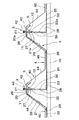
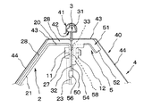
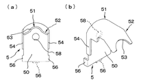
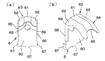
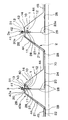
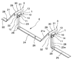
本発明の実施形態を添付の図面を参照して説明する。図1は、本発明に係る第1例の補強金具の使用例を示す正面図、図2は、同拡大正面図、図3(a)(b)は、第1例に係る補強金具の説明図であり、(a)は正面図、(b)は斜視図、図4(a)(b)は、第2例に係る補強金具の説明図であり、(a)は正面図、(b)は斜視図である。
【0021】
本発明に使用するタイトフレーム2、吊子3及び折板屋根板4などは、上記する従来例のものと同じ構成であるため、同じ符号を使用して説明する。
【0022】
本発明の補強金具は、図3に示する第1例に係る補強金具5と、図4に示す第2例に係る補強金具6とから構成されている。最初に、図3に示す第1例の補強金具5について説明すると、この補強金具5は、平らな垂直板50の上端円弧面から略水平に延びる円弧状体51が形成され、この円弧状体51の先端部に先端傾斜部52を備えており、先端傾斜部52の先端には、小形状の切込み面53が設けらている。
【0023】
そして、この垂直板50の両端側には、円弧状体51方向に屈曲させて、この円弧状体51と一体構成の強度を図る縁折り54,54が形成されている。しかし、この縁取り54は両端側に必ずも必要なものではなく、一方側のみに縁取り54を形成してもよいし、縁取り54を全く形成しなくてもよいが、強度性を考慮すると少なくとも一方の縁取り54は必要である。図中、58は、垂直板50に穿ったボルト穴である。
【0024】
さらに、この垂直板50の両端下端部には、円弧状体51の背面側に屈曲させた回動片56,56によりタイトフレーム2の垂下面23を挟むことで、補強金具5の回動を防ぎ、吊子3はフリーに動く。また、一方のみに回動片56を形成した場合も補強金具5の回動が防げる。回動片56が下端部のみに形成されている場合は、この回動片56がタイトフレーム2の垂下面23に設けたリブ28に入り、補強金具5の回動が妨げられるが、吊子3はフリーで動くため、その共回りがなくなる。
【0025】
図4に示す補強金具6は、平らな垂直板60の上端面から略水平に延びる長手方向中央部に平らな平坦面61と両端部が円弧面62,62を有する略円弧状体63が形成され、この先端傾斜部64を備えており、この先端には小形状の切込み面65が形成されている。
【0026】
さらに、この垂直板60には、上記する垂直板50と同じ構成の縁取り54と回動片56とが設けられている。つまり、垂直板60の両端側には、略円弧状体63方向に屈曲させて、この略円弧状体63と一体構成の強度を図る縁折り66,66が形成されているが、この縁取り66は両端側に必ずも必要なものではなく、一方側のみの縁取り66でもよいし、縁取り66を全く形成しなくてもよい。
【0027】
そして、この垂直板60の両端下端部には、円弧状体63の背面側に屈曲させた回動片67,67によりタイトフレーム2の垂下面23を挟むことで、補強金具6の回動を防ぎ、吊子3はフリーに動く。一方のみに回動片67形成した場合も補強金具6の回動が防げる。また、回動片67が下端部のみに形成されている場合は、この回動片67がタイトフレーム2の垂下面23に設けたリブ28に入り、補強金具6の回動が防げるが、吊子3はフリーで動くため、その共回りがなくなる。図中、69は、垂直板60に穿ったボルト穴である。
【0028】
これら補強金具5,6は、一枚の所定金属板を使用して、例えば、プレス加工などによって上記するような形状に加工されている。
【0029】
次に、このような補強金具5,6を用いたタイトフレーム2の使用例について説明するが、補強金具6の使用例は、補強金具5と同様に使用できるため、その説明を省略する。
【0030】
まず、上記するタイトフレーム2の取付部22,24,25を介して母屋70に取付け固定させる。この場合、タイトフレーム2の垂下面23の上端部には、予め本発明の補強金具5がボルト11とナット12で取付けられている。つまり、タイトフレーム2の垂下面23の上端部に、その円弧部31が上面20側に向けた吊子3を支持部32のボルト穴33と、補強金具5のボルト穴58とを一致させて垂下面23のボルト穴27に前記ボルト11を通してナット12を締めて、補強金具5がタイトフレーム2の垂下面23の上端部に締付けてある。
【0031】
そして、折板屋根4を敷設するには、上記するように敷設面に複数個のタイトフレーム2,2,…を配し、屋根の傾き角度に対応させて吊子3の傾き角度を調整させた後、そのボルト11とナット12とを強く締付ければよい。
【0032】
また、折板屋根4を敷設するには、上記従来例と同様に一方の折板屋根板40の外馳部41を左側の吊子3の円弧部31に係止させ、反対側の内馳部42を右側の吊子3aの円弧部31内に係止させるようにタイトフレーム2の垂下面23と傾斜面21aとの間に折板屋根板40を敷設すればよい。この外馳部41部分には、連接させる他の折板屋根板40aの内馳部42aを馳締めを行うことによって、順次同様な敷設作業を繰り返すことにより、折板屋根4を敷設させることができる。図中、43は折板屋根板40の上底、44はその傾斜面、45はその下底である。
【0033】
【発明の効果】
本発明は、以上の構成であれば、次のような効果がある。
▲1▼ 本発明の補強金具は、その回動片を介してタイトフレームと一体になり、吊子と一体に回動しないことにより吊子との共回りがなくなり、傾き角度の調整作業が極めて容易に行える。
▲2▼ 本発明の補強金具は、その縁折りが垂下板に形成されているため、その強度を著しく向上させることができる。
▲3▼ 本発明の補強金具は、従来のハンマーを使用しての調整作業でも締付け用のナットの緩みが防げる。
▲4▼ 本発明の補強金具は、その略水平に延びる円弧面と先端傾斜部とで折板屋根を支持できるため、折板屋根面への跡が付かない。
▲5▼ 本発明の補強金具は、一枚の金属板で構成できるため、その制作面でのコストがかからず、簡易に安価に提供できるものである。
【図面の簡単な説明】
【図1】 本発明に係る第1例の補強金具の使用例を示す正面図。
【図2】 同拡大正面図。
【図3】 図(a)(b)は、第1例に係る補強金具であり、図3aは正面図、図3bは斜視図。
【図4】 図(a)(b)は、第2例に係る補強金具であり、図4aは正面図、図4bは斜視図。
【図5】 従来例の正面図。
【図6】 タイトフレームの斜視図。
【符号の説明】
5 補強金具
50 垂直板
51 円弧状体
52 先端傾斜部
53 切込み面[0001]
BACKGROUND OF THE INVENTION
The present invention relates to a reinforcing metal fitting for a tight frame, and in particular, the reinforcing metal fitting eliminates a deviation from the tight frame main body, facilitates the adjustment work of the inclination angle of the suspension, and remarkably improves the strength of the reinforcing metal fitting, The present invention relates to a tight frame reinforcing metal fitting that prevents loosening of a tightening nut for fixing the reinforcing metal fitting and prevents a mark on the folded roof plate surface.
[0002]
[Prior art]
For example, a reinforcing
[0003]
The
[0004]
The
[0005]
The folded
[0006]
[Problems to be solved by the invention]
However, in the roof having the above-described configuration, for example, when adjusting the orientation of the
[0007]
In actual work, fine adjustment of this inclination is performed using a hammer. However, when the
[0008]
Moreover, although the
[0009]
The present invention has been invented in order to solve the above-described problems. The purpose of the present invention is to eliminate the displacement of the reinforcing bracket from the tight frame main body, and the adjustment work of the inclination angle of the hanging lever becomes extremely easy. Strength is also significantly improved, and further, it provides tight frame reinforcement brackets that prevent loosening of the tightening nuts that secure the reinforcement brackets and prevent traces on the folded roof plate surface. is there.
[0010]
[Means for Solving the Problems]
In order to solve the above-mentioned problem, the first invention of the present invention is characterized by comprising an arcuate body having a small cut surface at a tip inclined portion of an arcuate surface extending substantially horizontally from the upper end of a vertical plate. .
[0011]
According to a second aspect of the present invention, an edge fold connected to an arcuate body that improves strength at least in one end is bent at both ends of the vertical plate and bent toward the arcuate body side.
[0012]
According to a third aspect of the present invention, a rotating piece to be brought into contact with the hanging surface of the tight frame is bent to the back side at one end or lower end of both ends of the vertical plate.
[0013]
According to a fourth aspect of the present invention, the central portion in the longitudinal direction of the arcuate body is formed of a flat surface where the portion from the base end portion to the tip end portion is flat.
[0014]
5. The reinforcing metal fitting for tight frame according to claim 1 or 4, wherein the upper end of the vertical plate has an arcuate surface or a substantially central portion that is a flat surface, and both ends thereof are arcuate surfaces. .
[0015]
[Action]
According to the first invention, the folded-plate roof can be stably supported by the arcuate body having the substantially arcuate surface and the inclined front end cutting surface. Because it can support the folded-plate roof, there is no trace on the folded-plate roof surface.
[0016]
According to the second invention, since the edge fold is formed on at least one of the vertical plates as compared with the conventional product, the strength of the reinforcing metal fitting can be remarkably improved.
[0017]
According to the third invention, since the reinforcing metal fitting is not displaced from the tight frame, it is possible to easily adjust the inclination angle of the suspension as in the first invention.
[0018]
According to the fourth invention, similar to the first invention, since the reinforcing metal fitting is not displaced from the tight frame, the adjustment operation of the inclination angle of the suspension can be performed very easily, and the fixing metal fitting is fastened. Also prevents loosening of nuts. Furthermore, according to this reinforcing metal fitting, the folded plate roof can be supported by the arc surface extending substantially horizontally and the tip inclined portion, so that no trace is left on the folded plate roof surface.
[0019]
According to the fifth aspect of the present invention, it is an inexpensive tight frame reinforcing metal fitting having a simple arc arcuate body having a tip inclined portion and a flat arcuate body at the center.
[0020]
DETAILED DESCRIPTION OF THE INVENTION
Embodiments of the present invention will be described with reference to the accompanying drawings. FIG. 1 is a front view showing an example of use of a reinforcing metal fitting of the first example according to the present invention, FIG. 2 is an enlarged front view thereof, and FIGS. 3 (a) and 3 (b) are illustrations of the reinforcing metal fitting according to the first example. FIG. 4A is a front view, FIG. 4B is a perspective view, FIG. 4A and FIG. 4B are explanatory views of a reinforcing metal fitting according to a second example, FIG. ) Is a perspective view.
[0021]
Since the
[0022]
The reinforcing metal fitting of the present invention is composed of the reinforcing
[0023]
Further, edge folds 54 and 54 are formed at both ends of the
[0024]
Further, the lower end portion of the
[0025]
The reinforcing
[0026]
Further, the
[0027]
Then, at the lower ends of both ends of the
[0028]
These reinforcing
[0029]
Next, an example of use of the
[0030]
First, it is attached and fixed to the
[0031]
In order to lay the folded
[0032]
Further, in order to lay the folded
[0033]
【The invention's effect】
The present invention has the following effects with the above configuration.
(1) The reinforcing metal fitting of the present invention is integrated with the tight frame through the rotating piece, and since it does not rotate integrally with the suspension, there is no co-rotation with the suspension, and the tilt angle adjustment work is extremely difficult. Easy to do.
{Circle around (2)} The strength of the reinforcing metal fitting of the present invention can be remarkably improved because the edge fold is formed on the hanging plate.
(3) The reinforcing metal fitting of the present invention can prevent the tightening nut from being loosened even in an adjustment operation using a conventional hammer.
{Circle around (4)} The reinforcing metal fitting of the present invention can support the folded plate roof with its substantially horizontally extending circular arc surface and the tip inclined portion, so that there is no mark on the folded plate roof surface.
(5) Since the reinforcing metal fitting of the present invention can be composed of a single metal plate, the production cost is not required, and it can be provided simply and inexpensively.
[Brief description of the drawings]
FIG. 1 is a front view showing a usage example of a reinforcing metal fitting of a first example according to the present invention.
FIG. 2 is an enlarged front view of the same.
FIGS. 3A and 3B are reinforcing metal fittings according to a first example, FIG. 3A is a front view, and FIG. 3B is a perspective view.
FIGS. 4A and 4B are reinforcing metal fittings according to a second example, FIG. 4A is a front view, and FIG. 4B is a perspective view.
FIG. 5 is a front view of a conventional example.
FIG. 6 is a perspective view of a tight frame.
[Explanation of symbols]
5 Reinforcing
Claims (4)
Priority Applications (1)
| Application Number | Priority Date | Filing Date | Title |
|---|---|---|---|
| JP2002205123A JP4058616B2 (en) | 2002-07-15 | 2002-07-15 | Tight frame reinforcement bracket |
Applications Claiming Priority (1)
| Application Number | Priority Date | Filing Date | Title |
|---|---|---|---|
| JP2002205123A JP4058616B2 (en) | 2002-07-15 | 2002-07-15 | Tight frame reinforcement bracket |
Publications (2)
| Publication Number | Publication Date |
|---|---|
| JP2004044287A JP2004044287A (en) | 2004-02-12 |
| JP4058616B2 true JP4058616B2 (en) | 2008-03-12 |
Family
ID=31710508
Family Applications (1)
| Application Number | Title | Priority Date | Filing Date |
|---|---|---|---|
| JP2002205123A Expired - Fee Related JP4058616B2 (en) | 2002-07-15 | 2002-07-15 | Tight frame reinforcement bracket |
Country Status (1)
| Country | Link |
|---|---|
| JP (1) | JP4058616B2 (en) |
-
2002
- 2002-07-15 JP JP2002205123A patent/JP4058616B2/en not_active Expired - Fee Related
Also Published As
| Publication number | Publication date |
|---|---|
| JP2004044287A (en) | 2004-02-12 |
Similar Documents
| Publication | Publication Date | Title |
|---|---|---|
| JP3927479B2 (en) | Roof mounting bracket | |
| JPS604476A (en) | Angle adjusting type saddle | |
| JP3805430B2 (en) | Piping slide bracket | |
| JP4058616B2 (en) | Tight frame reinforcement bracket | |
| JP2002129695A (en) | Deflection bracket for hanging bracket | |
| JP4133312B2 (en) | securing bracket | |
| JPH0754417Y2 (en) | Wire-type reinforced hanging hardware for ceiling base materials | |
| JP3495404B2 (en) | Gutter fittings | |
| JP2003201752A (en) | Roof board mounting metal fixture and roof structure | |
| JP3044536B2 (en) | Slate roof replacement bracket and folded roof roof replacement bracket | |
| JPH10102670A (en) | Ceiling hanging bracket | |
| JPS635651B2 (en) | ||
| JP3127105U (en) | Pipe house reinforcement arch mounting bracket | |
| JP5128190B2 (en) | Suspension | |
| JP3043731U (en) | Scaffolding plate mounting bracket | |
| JP3004866U (en) | Architectural clamp | |
| JPH06499Y2 (en) | Gutter receiving device | |
| JPS6224658Y2 (en) | ||
| JPH0439861Y2 (en) | ||
| JPS6135633Y2 (en) | ||
| JPH0622024Y2 (en) | Gutter receiving device | |
| JP2001271486A (en) | Scaffold plate mounting structure | |
| JPH07324428A (en) | Hanger of channel for ceiling setting bed | |
| JP3031847U (en) | Roof snow stopper | |
| JP2604244Y2 (en) | Tight frame |
Legal Events
| Date | Code | Title | Description |
|---|---|---|---|
| A621 | Written request for application examination |
Free format text: JAPANESE INTERMEDIATE CODE: A621 Effective date: 20050707 |
|
| A977 | Report on retrieval |
Free format text: JAPANESE INTERMEDIATE CODE: A971007 Effective date: 20070620 |
|
| A131 | Notification of reasons for refusal |
Free format text: JAPANESE INTERMEDIATE CODE: A131 Effective date: 20070703 |
|
| A521 | Written amendment |
Free format text: JAPANESE INTERMEDIATE CODE: A523 Effective date: 20070903 |
|
| TRDD | Decision of grant or rejection written | ||
| A01 | Written decision to grant a patent or to grant a registration (utility model) |
Free format text: JAPANESE INTERMEDIATE CODE: A01 Effective date: 20071023 |
|
| A61 | First payment of annual fees (during grant procedure) |
Free format text: JAPANESE INTERMEDIATE CODE: A61 Effective date: 20071204 |
|
| FPAY | Renewal fee payment (event date is renewal date of database) |
Free format text: PAYMENT UNTIL: 20101228 Year of fee payment: 3 |
|
| R150 | Certificate of patent or registration of utility model |
Ref document number: 4058616 Country of ref document: JP Free format text: JAPANESE INTERMEDIATE CODE: R150 Free format text: JAPANESE INTERMEDIATE CODE: R150 |
|
| FPAY | Renewal fee payment (event date is renewal date of database) |
Free format text: PAYMENT UNTIL: 20111228 Year of fee payment: 4 |
|
| R250 | Receipt of annual fees |
Free format text: JAPANESE INTERMEDIATE CODE: R250 |
|
| FPAY | Renewal fee payment (event date is renewal date of database) |
Free format text: PAYMENT UNTIL: 20121228 Year of fee payment: 5 |
|
| R250 | Receipt of annual fees |
Free format text: JAPANESE INTERMEDIATE CODE: R250 |
|
| FPAY | Renewal fee payment (event date is renewal date of database) |
Free format text: PAYMENT UNTIL: 20121228 Year of fee payment: 5 |
|
| FPAY | Renewal fee payment (event date is renewal date of database) |
Free format text: PAYMENT UNTIL: 20121228 Year of fee payment: 5 |
|
| FPAY | Renewal fee payment (event date is renewal date of database) |
Free format text: PAYMENT UNTIL: 20131228 Year of fee payment: 6 |
|
| R250 | Receipt of annual fees |
Free format text: JAPANESE INTERMEDIATE CODE: R250 |
|
| R250 | Receipt of annual fees |
Free format text: JAPANESE INTERMEDIATE CODE: R250 |
|
| R250 | Receipt of annual fees |
Free format text: JAPANESE INTERMEDIATE CODE: R250 |
|
| R250 | Receipt of annual fees |
Free format text: JAPANESE INTERMEDIATE CODE: R250 |
|
| LAPS | Cancellation because of no payment of annual fees |