JP4058664B2 - Circuit breaker arc extinguishing device - Google Patents
Circuit breaker arc extinguishing device Download PDFInfo
- Publication number
- JP4058664B2 JP4058664B2 JP2000298208A JP2000298208A JP4058664B2 JP 4058664 B2 JP4058664 B2 JP 4058664B2 JP 2000298208 A JP2000298208 A JP 2000298208A JP 2000298208 A JP2000298208 A JP 2000298208A JP 4058664 B2 JP4058664 B2 JP 4058664B2
- Authority
- JP
- Japan
- Prior art keywords
- arc
- magnetic body
- arc extinguishing
- extinguishing device
- rod
- Prior art date
- Legal status (The legal status is an assumption and is not a legal conclusion. Google has not performed a legal analysis and makes no representation as to the accuracy of the status listed.)
- Expired - Lifetime
Links
Images


Landscapes
- Arc-Extinguishing Devices That Are Switches (AREA)
- Breakers (AREA)
Description
【0001】
【発明の属する技術分野】
この発明は、配線用遮断器や漏電遮断器などの回路遮断器において、電流遮断時に生じるアークを引き伸ばして消弧する消弧装置に関する。
【0002】
【従来の技術】
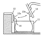
図6〜図9は従来の消弧装置を示すものである。図6の消弧装置はアーク吸引方式のもので、磁性板からU字状に折り曲げ形成された単一の磁性体11により構成されている。12は固定接触子、13は可動接触子で、磁性体11はその前後方向(図6の左右方向)が矢印で示す可動接触子13の開閉方向に略沿うように配置されている。電流遮断時に固定接点12aと可動接点13aとの間に生じるアーク14は、その磁束が磁性体11を通ることにより、図示のように消弧装置の底部に吸引されて引き伸ばされ、アーク電圧が上昇して消弧される。その際生じるアークガスは、消弧装置の右端から回路遮断器のケース外に排出される。
【0003】
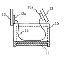
図7の消弧装置はアーク吸引・ガス冷却方式のもので、図6における磁性体11の内面を覆うように、アーク熱により消弧性の熱分解ガスを生じる絶縁物からなる絶縁体15が設けられている。電流遮断時に生じるアーク14は、図6の場合と同様に吸引されるとともに絶縁体15に押し付けられ、アーク熱を受ける絶縁体15が生じる消弧性ガスにより冷却されて消弧が促進される。図8の消弧装置も図7のものと同じであるが、磁性体11の上下方向が可動接触子の開閉方向に略沿うように配置されている。
【0004】
図9の消弧装置はアーク分割方式のもので、図9(A)は縦断面図、図9(B)はその横断面図である。図9において、磁性体11は磁性板からU字状に打ち抜かれたグリッド16が、隙間を置いて板厚方向に多数積層されて構成され、それらは左右一対の側板からなる絶縁体15に、左右両端でかしめ付けされて支持されている。アーク14は磁性体11に吸引されるとともに、グリッド16により分割され、アーク電圧が上昇して消弧される。
【0005】
【発明が解決しようとする課題】
上記した従来の消弧装置には、それぞれ次のような問題点がある。すなわち、(1)図6のものは、アーク14の伸張が進むと磁性体11に点弧して短絡状態となるため、高いアーク電圧が得られない。
(2)図7及び図8のものは、アークを絶縁体表面に押し付けて積極的に熱分解ガスを発生させるため、短絡電流などの大電流の遮断時に消弧装置の内圧が過大に上昇してアークガスが噴出し、消弧装置周辺を損傷する危険がある一方で、回路電圧が高く遮断電流が比較的小さい領域では、熱分解ガスの発生量が少ないためアーク電圧が十分に上がらない。すなわち、熱分解ガスの発生量により、遮断性能が左右される。また、その解決策として電圧に応じた消弧装置を準備しようとすると、消弧装置の種類が増え、コストアップの要因となる。
(3)図9のものは、図6〜図8のものに比べて磁気通路の断面積が小さく、従ってアークの吸引力も小さい。また、構造が複雑で、多数のグリッド16を絶縁体15に固定する作業に多くの工数を必要とする。
そこで、この発明の課題は、これら従来の消弧装置の難点を解消しながら利点を生かし、高性能で製作の容易な消弧装置を得ることにある。
【0006】
【課題を解決するための手段】
上記課題を解決するために、この発明は、左右一対の側板とその間を結ぶ底板とからなるU字状の磁性板により、電流遮断時に固定接点と可動接点との間に発生したアークを吸引する磁性体を形成し、その内面を前記アークの熱で消弧性の熱分解ガスを生じる絶縁体で被覆するとともに、前記磁性体の内側に前記底板から離して、前記側板と直交する向きの複数本の棒状磁性体を互いに間隔を介し、かつ前記磁性体から絶縁して配列するものとする(請求項1)。
【0007】
この請求項1の消弧装置は、図7の従来装置にアーク分割機能を付与したものに相当し、強力なアーク伸張機能に加えて、優れたアーク電圧上昇機能及びアーク冷却機能を有する。すなわち、接点間にアークが発生すると、このアークにより発生した磁束は、U字状の磁性体により強力に吸引されて伸張する。アークは伸張する過程で、磁性体の内面を被覆する絶縁体を加熱して熱分解ガスを発生させ、それにより冷却される。更に伸張すると、磁性体の内側に配置された棒状磁性体で発弧して分割され、陰極降下及び冷却によりアーク電圧が急速に高められて消弧される。従って、高電圧・小電流領域でも安定した消弧性能が得られる。
【0008】
請求項1の消弧装置において、前記棒状磁性体は左右一対の側板を有する絶縁物の支持体に支持させてユニットを構成し、このユニットを前記磁性体の内側に着脱可能に装着するようにするのがよい(請求項2)。これにより、ユニットを交換し、あるいはユニットの装着を省略することで、消弧装置全体を変更することなく、適用電圧及び遮断容量を変更することができる。その別手段として、前記絶縁体の側壁に前記棒状磁性体の支持穴を設けるとともに、この支持穴と同心で、かつこの支持穴よりも大径の挿通穴を前記磁性体の側板に設け、前記棒状磁性体を前記磁性体の側方から前記支持穴に着脱可能に装着するようにしてもよい(請求項3)。
【0009】
【発明の実施の形態】
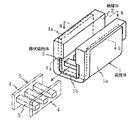
図1〜図3は、この発明の実施の形態を示すもので、図1は消弧装置の斜視図、図2は図1のII−II線に沿う断面図、図3は同じくIII−III線に沿う断面図である。図1〜図3において、左右一対の側板1aとその間を結ぶ底板1bとからなるU字状の磁性板(例えば鋼板)により磁性体1が形成され、その内面はアーク熱で消弧性の熱分解ガスを生じる絶縁体2で被覆されている。一方、3は例えば棒鋼からなる断面四角の棒状磁性体で、磁性体1の内側に前記底板1bから離されて、複数本(図示は3本)が側板1aと直交する向きに、互いに間隔を介して、かつ磁性体2から絶縁されて配置されている。
【0010】
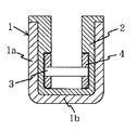
ここで、図3に示すように、絶縁体2の左右内壁面には段差が設けられ、棒状磁性体3は、この段差部分に嵌合するように設定された左右一対の側板4からなる絶縁物の支持体に、その両端が支持されてユニット5として構成されている。側板4は絶縁体2と同一の熱分解性の絶縁材が用いるのがよいが、他の材質の絶縁材でもよい。また、図示の場合、棒状磁性体3は側板4の成形時に両端が埋め込まれて固着されているが、かしめ付けやねじ締めにより固着してもよい。しかして、ユニット5は絶縁体1の上記段差部分に、図1の矢印方向に沿って着脱自在に装着される。
【0011】
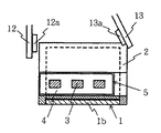
このような消弧装置は、固定接触子12及び可動接触子13に対して、例えば図2に示す位置関係で配置され、固定・可動接点12a,13a間に発生するアークを消弧する。その際、図7の従来構成と同等の磁気通路断面積及び熱分解ガス量により、アークを伸長させかつ冷却するるとともに、伸長させたアークを棒状磁性体3で分割・冷却して高い陰極降下によりアーク電圧を上昇させる。その結果、小電流でアーク駆動力及び熱分解ガスが発生しにくく、かつ高電圧(例えば600V)の遮断領域においても優れた消弧性能を発揮する。また、棒状磁性体3はユニット5として着脱自在であるため、ユニット5の交換のみで種々の適用電圧及び遮断電流に対応することができ、あるいは適用電圧によっては棒状磁性体3を省略することができる。
【0012】
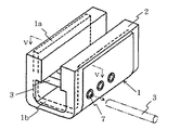
図4は、異なる実施の形態を示す消弧装置の斜視図、図5はそのV−V線に沿う断面図である。この実施の形態においては、棒状磁性体3は断面円形のものが用いられ、絶縁体2の側壁2aには棒状磁性体3と同径の支持穴6(図5)が設けられている。また、磁性体1の側板1aには、支持穴6と同心に、それよりも大径の挿通穴7が設けられている。そこで、棒状磁性体3は図示の通り、磁性体1の側方から挿通穴7を介して支持穴6に着脱可能に装着される。この消弧装置の機能・作用は図1のものと実質的に同じなので、その説明は省略する。
【0013】
【発明の効果】
以上の通り、この発明によれば、従来のアーク吸引・ガス冷却方式と遜色のないアーク吸引力及び熱分解ガス量が得られるとともに、伸長したアークを棒状磁性体間で分割して陰極降下により高いアーク電圧を発生させることができる。その結果、小電流・高電圧領域においても安定した遮断性能を得ることができ、また棒状磁性体を着脱可能とすることにより、消弧装置全体を大幅に変更することなく異なる適用電圧及び遮断容量に容易に対応することができる。
【図面の簡単な説明】
【図1】この発明の実施の形態を示す消弧装置の斜視図である。
【図2】図1のII−II線に沿う断面図である。
【図3】図1のIII−III線に沿う断面図である。
【図4】この発明の異なる実施の形態を示す消弧装置の斜視図である。
【図5】図4のV−V線に沿う断面図である。
【図6】従来例を示す消弧装置の縦断面図である。
【図7】異なる従来例を示す消弧装置の縦断面図である。
【図8】更に異なる従来例を示す消弧装置の縦断面図である。
【図9】更に異なる従来例を示し、(A)は消弧装置の縦断面図、(B)はその横断面図である。
【符号の説明】
1 磁性体
1a 側板
1b 底板
2 絶縁体
3 棒状磁性体
4 側板
5 ユニット
6 支持穴
7 挿通穴[0001]
BACKGROUND OF THE INVENTION
The present invention relates to an arc extinguishing device that extends and extinguishes an arc generated when a current is interrupted in a circuit breaker such as a circuit breaker for wiring or an earth leakage breaker.
[0002]
[Prior art]
6 to 9 show a conventional arc extinguishing device. The arc extinguishing apparatus of FIG. 6 is of an arc attraction type, and is composed of a single
[0003]
The arc extinguishing apparatus of FIG. 7 is of the arc suction / gas cooling type, and an
[0004]
The arc extinguishing apparatus of FIG. 9 is of the arc division type, FIG. 9 (A) is a longitudinal sectional view, and FIG. 9 (B) is a transverse sectional view thereof. In FIG. 9, the
[0005]
[Problems to be solved by the invention]
The conventional arc extinguishing apparatus described above has the following problems. That is, (1) In FIG. 6, when the extension of the
(2) In Fig. 7 and Fig. 8, the arc is pressed against the insulator surface to actively generate pyrolysis gas, so that the internal pressure of the arc extinguishing device increases excessively when a large current such as a short circuit current is interrupted. While the arc gas is blown out and there is a danger of damaging the periphery of the arc extinguishing device, the arc voltage is not sufficiently increased in a region where the circuit voltage is high and the breaking current is relatively small because the generation amount of pyrolysis gas is small. That is, the shutoff performance depends on the amount of pyrolysis gas generated. Moreover, if an attempt is made to prepare an arc extinguishing device corresponding to the voltage as a solution, the types of arc extinguishing devices increase, which causes an increase in cost.
(3) The cross-sectional area of the magnetic path in FIG. 9 is smaller than that in FIGS. Further, the structure is complicated, and a large number of man-hours are required for the work of fixing a large number of
Therefore, an object of the present invention is to obtain an arc extinguishing device that is easy to manufacture with high performance while taking advantage of these conventional arc extinguishing devices while solving the problems.
[0006]
[Means for Solving the Problems]
In order to solve the above problems, the present invention attracts an arc generated between a fixed contact and a movable contact when a current is interrupted by a U-shaped magnetic plate comprising a pair of left and right side plates and a bottom plate connecting the left and right side plates. A magnetic body is formed, and an inner surface thereof is covered with an insulator that generates an arc extinguishing pyrolysis gas by the heat of the arc, and a plurality of orientations that are separated from the bottom plate inside the magnetic body and perpendicular to the side plate It is assumed that the rod-shaped magnetic bodies are arranged so as to be spaced apart from each other and insulated from the magnetic bodies.
[0007]
The arc extinguishing apparatus of
[0008]
2. The arc-extinguishing apparatus according to
[0009]
DETAILED DESCRIPTION OF THE INVENTION
1 to 3 show an embodiment of the present invention. FIG. 1 is a perspective view of an arc extinguishing device, FIG. 2 is a sectional view taken along line II-II in FIG. 1, and FIG. It is sectional drawing which follows a line. 1 to 3, a
[0010]
Here, as shown in FIG. 3, a step is provided on the left and right inner wall surfaces of the
[0011]
Such an arc extinguishing device is arranged with respect to the fixed
[0012]
FIG. 4 is a perspective view of an arc extinguishing device showing a different embodiment, and FIG. 5 is a sectional view taken along the line VV. In this embodiment, the rod-shaped
[0013]
【The invention's effect】
As described above, according to the present invention, an arc attraction force and a pyrolysis gas amount comparable to those of the conventional arc attraction / gas cooling method can be obtained, and the elongated arc is divided between the rod-like magnetic bodies to reduce the cathode. A high arc voltage can be generated. As a result, a stable breaking performance can be obtained even in a small current / high voltage region, and by making the rod-shaped magnetic body detachable, different applied voltages and breaking capacities can be obtained without significantly changing the entire arc extinguishing device. Can be easily accommodated.
[Brief description of the drawings]
FIG. 1 is a perspective view of an arc extinguishing device showing an embodiment of the present invention.
2 is a cross-sectional view taken along line II-II in FIG.
FIG. 3 is a cross-sectional view taken along line III-III in FIG.
FIG. 4 is a perspective view of an arc extinguishing device showing a different embodiment of the present invention.
5 is a cross-sectional view taken along line VV in FIG.
FIG. 6 is a longitudinal sectional view of a conventional arc extinguishing device.
FIG. 7 is a longitudinal sectional view of an arc extinguishing device showing a different conventional example.
FIG. 8 is a longitudinal sectional view of an arc extinguishing apparatus showing still another conventional example.
FIG. 9 shows still another conventional example, in which (A) is a longitudinal sectional view of an arc extinguishing device, and (B) is a transverse sectional view thereof.
[Explanation of symbols]
DESCRIPTION OF
Claims (3)
Priority Applications (1)
| Application Number | Priority Date | Filing Date | Title |
|---|---|---|---|
| JP2000298208A JP4058664B2 (en) | 2000-09-29 | 2000-09-29 | Circuit breaker arc extinguishing device |
Applications Claiming Priority (1)
| Application Number | Priority Date | Filing Date | Title |
|---|---|---|---|
| JP2000298208A JP4058664B2 (en) | 2000-09-29 | 2000-09-29 | Circuit breaker arc extinguishing device |
Publications (2)
| Publication Number | Publication Date |
|---|---|
| JP2002110020A JP2002110020A (en) | 2002-04-12 |
| JP4058664B2 true JP4058664B2 (en) | 2008-03-12 |
Family
ID=18780195
Family Applications (1)
| Application Number | Title | Priority Date | Filing Date |
|---|---|---|---|
| JP2000298208A Expired - Lifetime JP4058664B2 (en) | 2000-09-29 | 2000-09-29 | Circuit breaker arc extinguishing device |
Country Status (1)
| Country | Link |
|---|---|
| JP (1) | JP4058664B2 (en) |
Families Citing this family (2)
| Publication number | Priority date | Publication date | Assignee | Title |
|---|---|---|---|---|
| JP5966469B2 (en) | 2012-03-15 | 2016-08-10 | オムロン株式会社 | Sealed contact device |
| FR2999783A1 (en) * | 2012-12-18 | 2014-06-20 | Schneider Electric Ind Sas | UNITARY CUT-OFF BLOCK AND CUTTING DEVICE, IN PARTICULAR A CONTACTOR COMPRISING AT LEAST ONE SUCH BLOCK |
-
2000
- 2000-09-29 JP JP2000298208A patent/JP4058664B2/en not_active Expired - Lifetime
Also Published As
| Publication number | Publication date |
|---|---|
| JP2002110020A (en) | 2002-04-12 |
Similar Documents
| Publication | Publication Date | Title |
|---|---|---|
| CN101562083B (en) | Arc chute assembly for a circuit breaker | |
| JP6554611B2 (en) | relay | |
| US20120211469A1 (en) | Circuit breaker with arc extinguishing mechanism | |
| CN104350563A (en) | A switching device | |
| CN112635252A (en) | Arc extinguishing structure of direct current contactor | |
| CN117813668A (en) | Bidirectional double break contactor | |
| JP4058664B2 (en) | Circuit breaker arc extinguishing device | |
| CN113782392A (en) | relay | |
| JP2004228087A (en) | Switch device and method of assembling the same | |
| CN212874379U (en) | Terminal clamp covering device for low voltage circuit breaker and corresponding low voltage circuit breaker | |
| JP4419642B2 (en) | Circuit breaker arc extinguishing device | |
| US2429846A (en) | Electric circuit interrupter | |
| JP2006059758A (en) | Circuit breaker arc extinguishing device | |
| JP6293075B2 (en) | Breaker | |
| JP2009087890A (en) | Circuit breaker | |
| KR970051615A (en) | Circuit breaker | |
| JPH08315706A (en) | Arc extinguishing device | |
| CN111540653B (en) | Arc extinguishing device of circuit breaker | |
| CN224190901U (en) | Relay device | |
| CN118712027A (en) | A contact arc extinguishing device | |
| JP2013149619A (en) | Arc chute and method of manufacturing the same | |
| US2798925A (en) | Split housing for circuit breakers held together by resilient clip | |
| JP2569241Y2 (en) | Circuit breaker | |
| JPH069392Y2 (en) | Arc-extinguishing device for electromagnetic contactor | |
| JPS6213323Y2 (en) |
Legal Events
| Date | Code | Title | Description |
|---|---|---|---|
| A621 | Written request for application examination |
Free format text: JAPANESE INTERMEDIATE CODE: A621 Effective date: 20040914 |
|
| A977 | Report on retrieval |
Free format text: JAPANESE INTERMEDIATE CODE: A971007 Effective date: 20070111 |
|
| A131 | Notification of reasons for refusal |
Free format text: JAPANESE INTERMEDIATE CODE: A131 Effective date: 20070322 |
|
| TRDD | Decision of grant or rejection written | ||
| A01 | Written decision to grant a patent or to grant a registration (utility model) |
Free format text: JAPANESE INTERMEDIATE CODE: A01 Effective date: 20071122 |
|
| A61 | First payment of annual fees (during grant procedure) |
Free format text: JAPANESE INTERMEDIATE CODE: A61 Effective date: 20071205 |
|
| FPAY | Renewal fee payment (event date is renewal date of database) |
Free format text: PAYMENT UNTIL: 20101228 Year of fee payment: 3 |
|
| R150 | Certificate of patent or registration of utility model |
Free format text: JAPANESE INTERMEDIATE CODE: R150 Ref document number: 4058664 Country of ref document: JP Free format text: JAPANESE INTERMEDIATE CODE: R150 |
|
| FPAY | Renewal fee payment (event date is renewal date of database) |
Free format text: PAYMENT UNTIL: 20101228 Year of fee payment: 3 |
|
| S111 | Request for change of ownership or part of ownership |
Free format text: JAPANESE INTERMEDIATE CODE: R313111 |
|
| FPAY | Renewal fee payment (event date is renewal date of database) |
Free format text: PAYMENT UNTIL: 20101228 Year of fee payment: 3 |
|
| R350 | Written notification of registration of transfer |
Free format text: JAPANESE INTERMEDIATE CODE: R350 |
|
| FPAY | Renewal fee payment (event date is renewal date of database) |
Free format text: PAYMENT UNTIL: 20101228 Year of fee payment: 3 |
|
| FPAY | Renewal fee payment (event date is renewal date of database) |
Free format text: PAYMENT UNTIL: 20111228 Year of fee payment: 4 |
|
| R250 | Receipt of annual fees |
Free format text: JAPANESE INTERMEDIATE CODE: R250 |
|
| FPAY | Renewal fee payment (event date is renewal date of database) |
Free format text: PAYMENT UNTIL: 20121228 Year of fee payment: 5 |
|
| R250 | Receipt of annual fees |
Free format text: JAPANESE INTERMEDIATE CODE: R250 |
|
| FPAY | Renewal fee payment (event date is renewal date of database) |
Free format text: PAYMENT UNTIL: 20121228 Year of fee payment: 5 |
|
| FPAY | Renewal fee payment (event date is renewal date of database) |
Free format text: PAYMENT UNTIL: 20131228 Year of fee payment: 6 |
|
| R250 | Receipt of annual fees |
Free format text: JAPANESE INTERMEDIATE CODE: R250 |
|
| R250 | Receipt of annual fees |
Free format text: JAPANESE INTERMEDIATE CODE: R250 |
|
| R250 | Receipt of annual fees |
Free format text: JAPANESE INTERMEDIATE CODE: R250 |
|
| R250 | Receipt of annual fees |
Free format text: JAPANESE INTERMEDIATE CODE: R250 |
|
| R250 | Receipt of annual fees |
Free format text: JAPANESE INTERMEDIATE CODE: R250 |
|
| R250 | Receipt of annual fees |
Free format text: JAPANESE INTERMEDIATE CODE: R250 |
|
| R250 | Receipt of annual fees |
Free format text: JAPANESE INTERMEDIATE CODE: R250 |
|
| R250 | Receipt of annual fees |
Free format text: JAPANESE INTERMEDIATE CODE: R250 |