JP4061114B2 - Crimp bonding equipment - Google Patents
Crimp bonding equipment Download PDFInfo
- Publication number
- JP4061114B2 JP4061114B2 JP2002114714A JP2002114714A JP4061114B2 JP 4061114 B2 JP4061114 B2 JP 4061114B2 JP 2002114714 A JP2002114714 A JP 2002114714A JP 2002114714 A JP2002114714 A JP 2002114714A JP 4061114 B2 JP4061114 B2 JP 4061114B2
- Authority
- JP
- Japan
- Prior art keywords
- workpieces
- rolling roller
- bonding apparatus
- pressure bonding
- moving
- Prior art date
- Legal status (The legal status is an assumption and is not a legal conclusion. Google has not performed a legal analysis and makes no representation as to the accuracy of the status listed.)
- Expired - Fee Related
Links
- 238000005096 rolling process Methods 0.000 claims description 58
- 238000000034 method Methods 0.000 claims description 7
- 238000002788 crimping Methods 0.000 claims description 6
- 230000002093 peripheral effect Effects 0.000 claims description 6
- 238000005304 joining Methods 0.000 claims description 4
- 230000006835 compression Effects 0.000 claims 1
- 238000007906 compression Methods 0.000 claims 1
- 238000003825 pressing Methods 0.000 description 9
- 239000000463 material Substances 0.000 description 3
- 230000003014 reinforcing effect Effects 0.000 description 3
- 238000004073 vulcanization Methods 0.000 description 3
- 238000005056 compaction Methods 0.000 description 1
- 238000010586 diagram Methods 0.000 description 1
- 238000006073 displacement reaction Methods 0.000 description 1
- 230000000694 effects Effects 0.000 description 1
- 230000003028 elevating effect Effects 0.000 description 1
- 238000004519 manufacturing process Methods 0.000 description 1
- 230000009466 transformation Effects 0.000 description 1
Images



Classifications
-
- B—PERFORMING OPERATIONS; TRANSPORTING
- B29—WORKING OF PLASTICS; WORKING OF SUBSTANCES IN A PLASTIC STATE IN GENERAL
- B29C—SHAPING OR JOINING OF PLASTICS; SHAPING OF MATERIAL IN A PLASTIC STATE, NOT OTHERWISE PROVIDED FOR; AFTER-TREATMENT OF THE SHAPED PRODUCTS, e.g. REPAIRING
- B29C66/00—General aspects of processes or apparatus for joining preformed parts
- B29C66/70—General aspects of processes or apparatus for joining preformed parts characterised by the composition, physical properties or the structure of the material of the parts to be joined; Joining with non-plastics material
- B29C66/71—General aspects of processes or apparatus for joining preformed parts characterised by the composition, physical properties or the structure of the material of the parts to be joined; Joining with non-plastics material characterised by the composition of the plastics material of the parts to be joined
-
- B—PERFORMING OPERATIONS; TRANSPORTING
- B29—WORKING OF PLASTICS; WORKING OF SUBSTANCES IN A PLASTIC STATE IN GENERAL
- B29C—SHAPING OR JOINING OF PLASTICS; SHAPING OF MATERIAL IN A PLASTIC STATE, NOT OTHERWISE PROVIDED FOR; AFTER-TREATMENT OF THE SHAPED PRODUCTS, e.g. REPAIRING
- B29C65/00—Joining or sealing of preformed parts, e.g. welding of plastics materials; Apparatus therefor
- B29C65/56—Joining or sealing of preformed parts, e.g. welding of plastics materials; Apparatus therefor using mechanical means or mechanical connections, e.g. form-fits
-
- B—PERFORMING OPERATIONS; TRANSPORTING
- B29—WORKING OF PLASTICS; WORKING OF SUBSTANCES IN A PLASTIC STATE IN GENERAL
- B29C—SHAPING OR JOINING OF PLASTICS; SHAPING OF MATERIAL IN A PLASTIC STATE, NOT OTHERWISE PROVIDED FOR; AFTER-TREATMENT OF THE SHAPED PRODUCTS, e.g. REPAIRING
- B29C65/00—Joining or sealing of preformed parts, e.g. welding of plastics materials; Apparatus therefor
- B29C65/78—Means for handling the parts to be joined, e.g. for making containers or hollow articles, e.g. means for handling sheets, plates, web-like materials, tubular articles, hollow articles or elements to be joined therewith; Means for discharging the joined articles from the joining apparatus
- B29C65/7802—Positioning the parts to be joined, e.g. aligning, indexing or centring
-
- B—PERFORMING OPERATIONS; TRANSPORTING
- B29—WORKING OF PLASTICS; WORKING OF SUBSTANCES IN A PLASTIC STATE IN GENERAL
- B29C—SHAPING OR JOINING OF PLASTICS; SHAPING OF MATERIAL IN A PLASTIC STATE, NOT OTHERWISE PROVIDED FOR; AFTER-TREATMENT OF THE SHAPED PRODUCTS, e.g. REPAIRING
- B29C66/00—General aspects of processes or apparatus for joining preformed parts
- B29C66/01—General aspects dealing with the joint area or with the area to be joined
- B29C66/05—Particular design of joint configurations
- B29C66/10—Particular design of joint configurations particular design of the joint cross-sections
- B29C66/11—Joint cross-sections comprising a single joint-segment, i.e. one of the parts to be joined comprising a single joint-segment in the joint cross-section
- B29C66/114—Single butt joints
- B29C66/1142—Single butt to butt joints
-
- B—PERFORMING OPERATIONS; TRANSPORTING
- B29—WORKING OF PLASTICS; WORKING OF SUBSTANCES IN A PLASTIC STATE IN GENERAL
- B29C—SHAPING OR JOINING OF PLASTICS; SHAPING OF MATERIAL IN A PLASTIC STATE, NOT OTHERWISE PROVIDED FOR; AFTER-TREATMENT OF THE SHAPED PRODUCTS, e.g. REPAIRING
- B29C66/00—General aspects of processes or apparatus for joining preformed parts
- B29C66/01—General aspects dealing with the joint area or with the area to be joined
- B29C66/345—Progressively making the joint, e.g. starting from the middle
- B29C66/3452—Making complete joints by combining partial joints
-
- B—PERFORMING OPERATIONS; TRANSPORTING
- B29—WORKING OF PLASTICS; WORKING OF SUBSTANCES IN A PLASTIC STATE IN GENERAL
- B29C—SHAPING OR JOINING OF PLASTICS; SHAPING OF MATERIAL IN A PLASTIC STATE, NOT OTHERWISE PROVIDED FOR; AFTER-TREATMENT OF THE SHAPED PRODUCTS, e.g. REPAIRING
- B29C66/00—General aspects of processes or apparatus for joining preformed parts
- B29C66/40—General aspects of joining substantially flat articles, e.g. plates, sheets or web-like materials; Making flat seams in tubular or hollow articles; Joining single elements to substantially flat surfaces
- B29C66/41—Joining substantially flat articles ; Making flat seams in tubular or hollow articles
- B29C66/43—Joining a relatively small portion of the surface of said articles
-
- B—PERFORMING OPERATIONS; TRANSPORTING
- B29—WORKING OF PLASTICS; WORKING OF SUBSTANCES IN A PLASTIC STATE IN GENERAL
- B29C—SHAPING OR JOINING OF PLASTICS; SHAPING OF MATERIAL IN A PLASTIC STATE, NOT OTHERWISE PROVIDED FOR; AFTER-TREATMENT OF THE SHAPED PRODUCTS, e.g. REPAIRING
- B29C66/00—General aspects of processes or apparatus for joining preformed parts
- B29C66/70—General aspects of processes or apparatus for joining preformed parts characterised by the composition, physical properties or the structure of the material of the parts to be joined; Joining with non-plastics material
- B29C66/73—General aspects of processes or apparatus for joining preformed parts characterised by the composition, physical properties or the structure of the material of the parts to be joined; Joining with non-plastics material characterised by the intensive physical properties of the material of the parts to be joined, by the optical properties of the material of the parts to be joined, by the extensive physical properties of the parts to be joined, by the state of the material of the parts to be joined or by the material of the parts to be joined being a thermoplastic or a thermoset
- B29C66/737—General aspects of processes or apparatus for joining preformed parts characterised by the composition, physical properties or the structure of the material of the parts to be joined; Joining with non-plastics material characterised by the intensive physical properties of the material of the parts to be joined, by the optical properties of the material of the parts to be joined, by the extensive physical properties of the parts to be joined, by the state of the material of the parts to be joined or by the material of the parts to be joined being a thermoplastic or a thermoset characterised by the state of the material of the parts to be joined
- B29C66/7375—General aspects of processes or apparatus for joining preformed parts characterised by the composition, physical properties or the structure of the material of the parts to be joined; Joining with non-plastics material characterised by the intensive physical properties of the material of the parts to be joined, by the optical properties of the material of the parts to be joined, by the extensive physical properties of the parts to be joined, by the state of the material of the parts to be joined or by the material of the parts to be joined being a thermoplastic or a thermoset characterised by the state of the material of the parts to be joined uncured, partially cured or fully cured
- B29C66/73751—General aspects of processes or apparatus for joining preformed parts characterised by the composition, physical properties or the structure of the material of the parts to be joined; Joining with non-plastics material characterised by the intensive physical properties of the material of the parts to be joined, by the optical properties of the material of the parts to be joined, by the extensive physical properties of the parts to be joined, by the state of the material of the parts to be joined or by the material of the parts to be joined being a thermoplastic or a thermoset characterised by the state of the material of the parts to be joined uncured, partially cured or fully cured the to-be-joined area of at least one of the parts to be joined being uncured, i.e. non cross-linked, non vulcanized
- B29C66/73752—General aspects of processes or apparatus for joining preformed parts characterised by the composition, physical properties or the structure of the material of the parts to be joined; Joining with non-plastics material characterised by the intensive physical properties of the material of the parts to be joined, by the optical properties of the material of the parts to be joined, by the extensive physical properties of the parts to be joined, by the state of the material of the parts to be joined or by the material of the parts to be joined being a thermoplastic or a thermoset characterised by the state of the material of the parts to be joined uncured, partially cured or fully cured the to-be-joined area of at least one of the parts to be joined being uncured, i.e. non cross-linked, non vulcanized the to-be-joined areas of both parts to be joined being uncured
-
- B—PERFORMING OPERATIONS; TRANSPORTING
- B29—WORKING OF PLASTICS; WORKING OF SUBSTANCES IN A PLASTIC STATE IN GENERAL
- B29C—SHAPING OR JOINING OF PLASTICS; SHAPING OF MATERIAL IN A PLASTIC STATE, NOT OTHERWISE PROVIDED FOR; AFTER-TREATMENT OF THE SHAPED PRODUCTS, e.g. REPAIRING
- B29C66/00—General aspects of processes or apparatus for joining preformed parts
- B29C66/80—General aspects of machine operations or constructions and parts thereof
- B29C66/81—General aspects of the pressing elements, i.e. the elements applying pressure on the parts to be joined in the area to be joined, e.g. the welding jaws or clamps
- B29C66/814—General aspects of the pressing elements, i.e. the elements applying pressure on the parts to be joined in the area to be joined, e.g. the welding jaws or clamps characterised by the design of the pressing elements, e.g. of the welding jaws or clamps
- B29C66/8141—General aspects of the pressing elements, i.e. the elements applying pressure on the parts to be joined in the area to be joined, e.g. the welding jaws or clamps characterised by the design of the pressing elements, e.g. of the welding jaws or clamps characterised by the surface geometry of the part of the pressing elements, e.g. welding jaws or clamps, coming into contact with the parts to be joined
- B29C66/81433—General aspects of the pressing elements, i.e. the elements applying pressure on the parts to be joined in the area to be joined, e.g. the welding jaws or clamps characterised by the design of the pressing elements, e.g. of the welding jaws or clamps characterised by the surface geometry of the part of the pressing elements, e.g. welding jaws or clamps, coming into contact with the parts to be joined being toothed, i.e. comprising several teeth or pins, or being patterned
-
- B—PERFORMING OPERATIONS; TRANSPORTING
- B29—WORKING OF PLASTICS; WORKING OF SUBSTANCES IN A PLASTIC STATE IN GENERAL
- B29C—SHAPING OR JOINING OF PLASTICS; SHAPING OF MATERIAL IN A PLASTIC STATE, NOT OTHERWISE PROVIDED FOR; AFTER-TREATMENT OF THE SHAPED PRODUCTS, e.g. REPAIRING
- B29C66/00—General aspects of processes or apparatus for joining preformed parts
- B29C66/80—General aspects of machine operations or constructions and parts thereof
- B29C66/81—General aspects of the pressing elements, i.e. the elements applying pressure on the parts to be joined in the area to be joined, e.g. the welding jaws or clamps
- B29C66/814—General aspects of the pressing elements, i.e. the elements applying pressure on the parts to be joined in the area to be joined, e.g. the welding jaws or clamps characterised by the design of the pressing elements, e.g. of the welding jaws or clamps
- B29C66/8141—General aspects of the pressing elements, i.e. the elements applying pressure on the parts to be joined in the area to be joined, e.g. the welding jaws or clamps characterised by the design of the pressing elements, e.g. of the welding jaws or clamps characterised by the surface geometry of the part of the pressing elements, e.g. welding jaws or clamps, coming into contact with the parts to be joined
- B29C66/81433—General aspects of the pressing elements, i.e. the elements applying pressure on the parts to be joined in the area to be joined, e.g. the welding jaws or clamps characterised by the design of the pressing elements, e.g. of the welding jaws or clamps characterised by the surface geometry of the part of the pressing elements, e.g. welding jaws or clamps, coming into contact with the parts to be joined being toothed, i.e. comprising several teeth or pins, or being patterned
- B29C66/81435—General aspects of the pressing elements, i.e. the elements applying pressure on the parts to be joined in the area to be joined, e.g. the welding jaws or clamps characterised by the design of the pressing elements, e.g. of the welding jaws or clamps characterised by the surface geometry of the part of the pressing elements, e.g. welding jaws or clamps, coming into contact with the parts to be joined being toothed, i.e. comprising several teeth or pins, or being patterned comprising several parallel ridges, e.g. for crimping
-
- B—PERFORMING OPERATIONS; TRANSPORTING
- B29—WORKING OF PLASTICS; WORKING OF SUBSTANCES IN A PLASTIC STATE IN GENERAL
- B29C—SHAPING OR JOINING OF PLASTICS; SHAPING OF MATERIAL IN A PLASTIC STATE, NOT OTHERWISE PROVIDED FOR; AFTER-TREATMENT OF THE SHAPED PRODUCTS, e.g. REPAIRING
- B29C66/00—General aspects of processes or apparatus for joining preformed parts
- B29C66/80—General aspects of machine operations or constructions and parts thereof
- B29C66/81—General aspects of the pressing elements, i.e. the elements applying pressure on the parts to be joined in the area to be joined, e.g. the welding jaws or clamps
- B29C66/814—General aspects of the pressing elements, i.e. the elements applying pressure on the parts to be joined in the area to be joined, e.g. the welding jaws or clamps characterised by the design of the pressing elements, e.g. of the welding jaws or clamps
- B29C66/8145—General aspects of the pressing elements, i.e. the elements applying pressure on the parts to be joined in the area to be joined, e.g. the welding jaws or clamps characterised by the design of the pressing elements, e.g. of the welding jaws or clamps characterised by the constructional aspects of the pressing elements, e.g. of the welding jaws or clamps
- B29C66/81463—General aspects of the pressing elements, i.e. the elements applying pressure on the parts to be joined in the area to be joined, e.g. the welding jaws or clamps characterised by the design of the pressing elements, e.g. of the welding jaws or clamps characterised by the constructional aspects of the pressing elements, e.g. of the welding jaws or clamps comprising a plurality of single pressing elements, e.g. a plurality of sonotrodes, or comprising a plurality of single counter-pressing elements, e.g. a plurality of anvils, said plurality of said single elements being suitable for making a single joint
- B29C66/81465—General aspects of the pressing elements, i.e. the elements applying pressure on the parts to be joined in the area to be joined, e.g. the welding jaws or clamps characterised by the design of the pressing elements, e.g. of the welding jaws or clamps characterised by the constructional aspects of the pressing elements, e.g. of the welding jaws or clamps comprising a plurality of single pressing elements, e.g. a plurality of sonotrodes, or comprising a plurality of single counter-pressing elements, e.g. a plurality of anvils, said plurality of said single elements being suitable for making a single joint one placed behind the other in a single row in the feed direction
-
- B—PERFORMING OPERATIONS; TRANSPORTING
- B29—WORKING OF PLASTICS; WORKING OF SUBSTANCES IN A PLASTIC STATE IN GENERAL
- B29C—SHAPING OR JOINING OF PLASTICS; SHAPING OF MATERIAL IN A PLASTIC STATE, NOT OTHERWISE PROVIDED FOR; AFTER-TREATMENT OF THE SHAPED PRODUCTS, e.g. REPAIRING
- B29C66/00—General aspects of processes or apparatus for joining preformed parts
- B29C66/80—General aspects of machine operations or constructions and parts thereof
- B29C66/81—General aspects of the pressing elements, i.e. the elements applying pressure on the parts to be joined in the area to be joined, e.g. the welding jaws or clamps
- B29C66/814—General aspects of the pressing elements, i.e. the elements applying pressure on the parts to be joined in the area to be joined, e.g. the welding jaws or clamps characterised by the design of the pressing elements, e.g. of the welding jaws or clamps
- B29C66/8145—General aspects of the pressing elements, i.e. the elements applying pressure on the parts to be joined in the area to be joined, e.g. the welding jaws or clamps characterised by the design of the pressing elements, e.g. of the welding jaws or clamps characterised by the constructional aspects of the pressing elements, e.g. of the welding jaws or clamps
- B29C66/81463—General aspects of the pressing elements, i.e. the elements applying pressure on the parts to be joined in the area to be joined, e.g. the welding jaws or clamps characterised by the design of the pressing elements, e.g. of the welding jaws or clamps characterised by the constructional aspects of the pressing elements, e.g. of the welding jaws or clamps comprising a plurality of single pressing elements, e.g. a plurality of sonotrodes, or comprising a plurality of single counter-pressing elements, e.g. a plurality of anvils, said plurality of said single elements being suitable for making a single joint
- B29C66/81469—General aspects of the pressing elements, i.e. the elements applying pressure on the parts to be joined in the area to be joined, e.g. the welding jaws or clamps characterised by the design of the pressing elements, e.g. of the welding jaws or clamps characterised by the constructional aspects of the pressing elements, e.g. of the welding jaws or clamps comprising a plurality of single pressing elements, e.g. a plurality of sonotrodes, or comprising a plurality of single counter-pressing elements, e.g. a plurality of anvils, said plurality of said single elements being suitable for making a single joint one placed next to the other in a single line transverse to the feed direction, e.g. shoulder to shoulder sonotrodes
-
- B—PERFORMING OPERATIONS; TRANSPORTING
- B29—WORKING OF PLASTICS; WORKING OF SUBSTANCES IN A PLASTIC STATE IN GENERAL
- B29C—SHAPING OR JOINING OF PLASTICS; SHAPING OF MATERIAL IN A PLASTIC STATE, NOT OTHERWISE PROVIDED FOR; AFTER-TREATMENT OF THE SHAPED PRODUCTS, e.g. REPAIRING
- B29C66/00—General aspects of processes or apparatus for joining preformed parts
- B29C66/80—General aspects of machine operations or constructions and parts thereof
- B29C66/82—Pressure application arrangements, e.g. transmission or actuating mechanisms for joining tools or clamps
- B29C66/824—Actuating mechanisms
- B29C66/8242—Pneumatic or hydraulic drives
-
- B—PERFORMING OPERATIONS; TRANSPORTING
- B29—WORKING OF PLASTICS; WORKING OF SUBSTANCES IN A PLASTIC STATE IN GENERAL
- B29C—SHAPING OR JOINING OF PLASTICS; SHAPING OF MATERIAL IN A PLASTIC STATE, NOT OTHERWISE PROVIDED FOR; AFTER-TREATMENT OF THE SHAPED PRODUCTS, e.g. REPAIRING
- B29C66/00—General aspects of processes or apparatus for joining preformed parts
- B29C66/80—General aspects of machine operations or constructions and parts thereof
- B29C66/83—General aspects of machine operations or constructions and parts thereof characterised by the movement of the joining or pressing tools
- B29C66/836—Moving relative to and tangentially to the parts to be joined, e.g. transversely to the displacement of the parts to be joined, e.g. using a X-Y table
- B29C66/8362—Rollers, cylinders or drums moving relative to and tangentially to the parts to be joined
-
- B—PERFORMING OPERATIONS; TRANSPORTING
- B29—WORKING OF PLASTICS; WORKING OF SUBSTANCES IN A PLASTIC STATE IN GENERAL
- B29C—SHAPING OR JOINING OF PLASTICS; SHAPING OF MATERIAL IN A PLASTIC STATE, NOT OTHERWISE PROVIDED FOR; AFTER-TREATMENT OF THE SHAPED PRODUCTS, e.g. REPAIRING
- B29C66/00—General aspects of processes or apparatus for joining preformed parts
- B29C66/80—General aspects of machine operations or constructions and parts thereof
- B29C66/84—Specific machine types or machines suitable for specific applications
- B29C66/843—Machines for making separate joints at the same time in different planes; Machines for making separate joints at the same time mounted in parallel or in series
- B29C66/8432—Machines for making separate joints at the same time mounted in parallel or in series
-
- B—PERFORMING OPERATIONS; TRANSPORTING
- B29—WORKING OF PLASTICS; WORKING OF SUBSTANCES IN A PLASTIC STATE IN GENERAL
- B29C—SHAPING OR JOINING OF PLASTICS; SHAPING OF MATERIAL IN A PLASTIC STATE, NOT OTHERWISE PROVIDED FOR; AFTER-TREATMENT OF THE SHAPED PRODUCTS, e.g. REPAIRING
- B29C66/00—General aspects of processes or apparatus for joining preformed parts
- B29C66/70—General aspects of processes or apparatus for joining preformed parts characterised by the composition, physical properties or the structure of the material of the parts to be joined; Joining with non-plastics material
- B29C66/72—General aspects of processes or apparatus for joining preformed parts characterised by the composition, physical properties or the structure of the material of the parts to be joined; Joining with non-plastics material characterised by the structure of the material of the parts to be joined
- B29C66/721—Fibre-reinforced materials
- B29C66/7214—Fibre-reinforced materials characterised by the length of the fibres
- B29C66/72141—Fibres of continuous length
Landscapes
- Engineering & Computer Science (AREA)
- Mechanical Engineering (AREA)
- Physics & Mathematics (AREA)
- Fluid Mechanics (AREA)
- Tyre Moulding (AREA)
Description
【0001】
【発明の属する技術分野】
本発明は、加硫前のゴム製板材、その他の圧着することにより接合する性質を有する複数のワーク同士を、互いに圧着接合させる装置に関する。
【0002】
【従来の技術】
タイヤの製造工程には、連続帯板状に形成された加硫前のゴム製板材(内部に補強用コードを埋設することもある)を、所要長で切断し、切断された短片の向きを変えて順次接合する工程がある。
このような工程で使用される従来の圧着接合装置としては、2枚の短寸のゴム製板材(以下ワークという)の対向端部を、対向する2個の受板上に載置し、それらの上方から、油圧シリンダ等の昇降手段の作動により下降させられるようにした昇降体に、平行リンク機構をもって支持された1対の押圧パッドを押圧し、その後昇降体がさらに下降させられることにより、押圧パッドが平行リンク機構の作用により、互いに近接する方向に移動させられて、両ワークの端面同士を互いに突き合わせるようにした装置がある。
【0003】
上記1対の受板は、昇降体の下降とタイミングを合わせて、油圧シリンダ等により互いに近接する方向に移動させられるようになっている。
【0004】
【発明が解決しようとする課題】
しかし、上述のような従来の装置では、2個のワークの対向端面全体を同時に圧着させるので、大型の強力な昇降手段等を必要とし、厚さの大きいワークには対応できず、また両ワークの接合前の位置決めを正確に行なわなければならない等の問題がある。
【0005】
本発明は、従来の技術が有する上記のような問題点に鑑み、厚さの厚いワーク同士を軽力で、正確かつ簡単に圧着させることができるようにした圧着接合装置を提供することを目的としている。
【0006】
【課題を解決するための手段】
本発明によると、上記課題は次のようにして解決される。
(1) 複数のワークの突き合わせ面に沿って移動する移動体に、前記各ワークの突き合わせ面に近接する部分に圧接して転動するようにした上下に対向する少なくとも2対の転圧ローラを、各回転軸線を進行方向と逆方向に向かって互いにハ字状に拡開するように傾斜させて装着し、前記転圧ローラをもって、複数のワークの突き合わせ面に近接する部分を上下から挟むようにし、かつ下方の転圧ローラの外径を、上方の転圧ローラの外径より大とする。
【0007】
( 2 ) 上記( 1 ) 項において、移動体に、複数対の転圧ローラを、進行方向に並べて配設する。
【0008】
( 3 ) 上記( 2 )項において、進行方向前寄りの転圧ローラの傾斜角度を、進行方向後寄りの転圧ローラの傾斜角度より急傾斜とする。
【0009】
(4) 複数のワークの突き合わせ面に沿って移動する移動体に、前記各ワークの突き合わせ面に近接する部分に圧接して転動するようにした複数対の転圧ローラを、進行方向に並べて配設するとともに、各回転軸線を進行方向と逆方向に向かって互いにハ字状に拡開するように傾斜させて装着し、かつ進行方向前寄りの転圧ローラの傾斜角度を、進行方向後寄りの転圧ローラの傾斜角度より急傾斜とする。
【0010】
( 5 ) 上記(1)〜( 4 )項のいずれかにおいて、移動体に、各転圧ローラをワークに対して遠近移動させる移動手段を設ける。
【0011】
( 6 ) 上記(1)〜( 5 )項のいずれかにおいて、各転圧ローラの外周面に、円環状または螺旋状の凹凸条を設ける。
【0012】
( 7 ) 上記( 6 )項において、各転圧ローラの内方寄りの凹凸条のピッチを、外方寄りの凹凸条のピッチより小とする。
【0013】
( 8 ) 上記(1)〜( 7 )項のいずれかにおいて、1対の転圧ローラのそれぞれの内端部に冠歯車を形成し、それらを互いに噛合させる。
【0014】
( 9 ) 上記(1)〜( 8 )項のいずれかにおいて、移動体に、複数のワークの対向端面間に介入し、移動体と各ワークの端面とを位置決めする薄板状のガイド板を設ける。
【0015】
(10) 上記( 9 )項において、ガイド板により、移動体の上部と下部とを互いに連結する。
【0016】
(11) 上記(1)〜(10)項のいずれかにおいて、圧着作業用の進行方向を互いに外向きとした2台の移動体を、複数のワークの突き合わせ面に沿って移動可能として配設する。
【0017】
【発明の実施の形態】
図1〜図7は、本発明の第1の実施形態を示す。
図1及び図2に示すように、圧着接合装置(A)は、加硫前のタイヤ形成用のゴム製板材である多数のワーク(B)(C)を、図1の矢印方向である前方に向かって順次搬送することのできる前後のコンベヤ(D)(E)間に配設されている。
【0018】
各コンベヤ(D)(E)は、その一部を図4に想像線で詳細に示してあるが、ローラコンベヤ、ベルトコンベヤ、またはその他の公知の構造のものとすることができる。
【0019】
圧着接合装置(A)は、支持体(1)に支持された左右方向を向く上下1対のガイドレール(2)(2)に摺動自在に装着された左右1対の移動体(3)(3)を備えている。
【0020】
各移動体(3)は、上下のガイドレール(2)(2)間に配設された左右方向を向くねじ軸(4)と螺合し、各ねじ軸(4)を、左右の支持体(1)の外側に配設されたモータ(5)により正逆回転させることにより、図2に実線で示すような最も外側の退避位置から、図2に想像線で示す(左方の移動体(3)のみ)ように、装置全体の中心線(CL)を越えたオーバーラン位置までの間を、互いに独立して移動しうるようになっている。
【0021】
左右の移動体(3)(3)は、互いに左右対称構造をなしているので、以下の説明では、その左方のもののみについて詳細に説明し、右方のものについては詳細な説明を省略する。
【0022】
図3〜図5に示すように、左方の移動体(3)は、コンベヤ(D)(E)により形成されるワーク(B)(C)の搬送面(6)より下方に位置する下部(3a)と、同じく上方に位置する上部(3b)とからなり、両部(3a)(3b)は、左右方向を向いて起立する薄板状のガイド板(7)により互いに連結されている。
【0023】
ガイド板(7)は、前後のワーク(B)(C)の対向面間に介入し、移動体(3)と各ワーク(B)(C)の端面とを位置決めする作用をする。
【0024】
ガイド板(7)の中位部両側面には、前後のワーク(B)(C)の対向端部を、搬送面(6)において受支する水平受片(8)が固着されている。
【0025】
移動体(3)の上部(3b)におけるコラム(9)の内面には、下向きのエアシリンダ装置よりなる移動手段(10)により昇降させられるようにした可動ヘッド(11)が上下方向に摺動可能として装着されている。
【0026】
可動ヘッド(11)の下端部と、それに対向するように移動体(3)の下部(3a)の上面に設けられた固定ヘッド(12)の上端部とには、前後方向を向くガイドローラ(13)と、前後2対の転圧ローラ(14)(14)(15)(15)とが、それぞれ上下に対応するようにして、移動体(3)の圧着作業時の進行方向(この例では、左方の移動体(3)は左方、右方の移動体(3)は右方)に沿って順次設けられている。
【0027】
真直の上下のガイドローラ(13)(13)は、それらの間に、前後のワーク(B)(C)の対向縁部を上下から挟みつけることにより、両ワーク(B)(C)の対向縁部同士が上下に重なったり、前後または左右に位置ずれしたりするのを防止する作用をする。
【0028】
前後に対をなす転圧ローラ(14)(14)(15)(15)は、移動体(3)の圧着作業時の進行方向と逆方向、すなわち右方に向かって平面視において互いにハ字状に拡開するように、片持ち状の傾斜軸(16)(17)をもって、可動ヘッド(11)及び固定ヘッド(12)にそれぞれ枢支されている。
【0029】
この例では、左右の転圧ローラ(14)(15)は互いに平行とし、それぞれが移動体(3)の進行方向に対して100°〜110°(進行方向と逆の方向に対して80°〜70°)だけ傾斜するようにしてある。
【0030】
前後の転圧ローラ(14)(14)、(15)(15)の互いに対向する端部には、冠歯車(18)が形成されており、それらを互いに噛合させることにより、前後の転圧ローラ(14)(14)は、互いに同期して回転するようになっている。
【0031】
図6に示すように、各転圧ローラ(14)(15)における冠歯車(18)を含む内端部の外周面には、内端を向く面が垂直をなし、かつ外端を向く面が傾斜面をなす鋸歯状の円環状または螺旋状の凹凸条(19)が、同じくそれ以外の外周面には、上記凹凸条(19)よりピッチ及び歯形を大とした相似形の凹凸条(20)がそれぞれ形成されている。
【0032】
なお、各転圧ローラ(14)(15)の凹凸条(19)(20)を螺旋とする場合は、後方の転圧ローラ(14)(15)の凹凸条(19)(20)は右ねじ、また前方の転圧ローラ(14)(15)の凹凸条(19)(20)は左ねじとするのが好ましい。
【0033】
次に、この圧着接合装置(A)の操作要領と作用について、図7を参照して説明する。なお、この操作要領は一例であって、他の異なる操作要領に従って操作してもよいことはもちろんである。
【0034】
図7(A)に示すように、左右の移動体(3)(3)を退避位置に位置させた状態で、図1に示すように、前後のワーク(B)(C)を、その対向端部同士が、各移動体(3)のガイド板(7)の移動軌跡上で互いに突き合わされるか、または近接するようにして、コンベヤ(D)(E)上に配置する。
【0035】
次に、両移動体(3)(3)を、その可動ヘッド(11)を上昇させた状態で、図7(B)に示すように、装置の中央において互いに近接する位置まで内向きに移動させた後、両移動体(3)(3)の可動ヘッド(11)を下降し、上下のガイドローラ(13)及び転圧ローラ(14)(15)で、前後のワーク(B)(C)の対向端部を上下から挾圧把持する。
【0036】
このときの可動ヘッド(11)の下向きの押圧力が、ワーク(B)(C)の厚さに応じた最適な値となるように、移動手段(10)であるエアシリンダ装置の空気圧を調節するのが好ましい。
【0037】
次いで、図7(C)に示すように、右方の移動体(3)のみを右方にわずかだけ、少なくとも左方の移動体(3)の中心線(CL)から右方へオーバーランしうる量だけ、移動させる。
すると、左方の移動体(3)により、両ワーク(B)(C)の対向端部のほぼ中央部が上下から把持された状態で、右方の移動体(3)の移動により、その上下のガイドローラ(13)及び転圧ローラ(14)(15)がワーク(B)(C)の対応端部の上下面に沿って転動する。
【0038】
このとき、前後の転圧ローラ(14)(15)が上述のように傾斜していることにより、ワーク(B)(C)の対向端部同士は、ファスナを閉じるような態様で、順次圧着接合される。
【0039】
図7(D)に示すように、右方の移動体(3)が予め定めた位置に達すると、その移動を停止し、そのままの状態で、左方の移動体(3)における可動ヘッド(11)を上昇させ、その後左方の移動体(3)をオーバーラン位置まで移動させ、ここで再度可動ヘッド(11)を下降させた後、図7(E)に示すように、左右の移動体(3)(3)を、同時に外向きに移動させる。
【0040】
すると、図7(C)について上述したのと同様の作用により、ワーク(B)(C)の対向端部同士は、ほぼ中央部から両側方に向かって、ファスナを閉じるような態様で、漸次圧着接合される。
【0041】
図7(F)に示すように、左右の移動体(3)(3)が、両ワーク(B)(C)から外側方に外れて、元の退避位置に達すると、そこでそれらの移動を停止した後、各可動ヘッド(11)を上昇させて、次の作業に備える。
【0042】
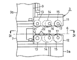
図8及び図9は、本発明の第2の実施形態を示す。なお、第1の実施形態におけるのと同一の部材には同一の符号を付して図示するに止め、それらについての詳細な説明は省略する。
【0043】
この例では、左右方向に並ぶ複数対の転圧ローラ(14)(15)のうち、圧着作業時の進行方向の前寄りの転圧ローラ(14)の傾斜角度を、同じく後寄りの転圧ローラ(15)の傾斜角度より急傾斜としてある。
【0044】
このようにすることにより、前後のワーク(B)(C)の対向端部同士は、最初に前寄りの転圧ローラ(14)(14)により、互いに強力に引き寄せられた後、後寄りの転圧ローラ(15)(15)により、性状の安定化及び均一化を図ることができる。
【0045】
また、この例では、固定ヘッド(12)側のガイドローラ(13)及び転圧ローラ(14)(15)の外径を、すべて可動ヘッド(11)側のものより大としてある。
【0046】
このようにすると、補強コードから表面までの寸法である糸上ゲージと、補強コードから裏面までの寸法である糸下ゲージとが互いに異なるオッドゲージタイプのワーク(B)(C)の圧着接合に最適に対応することができる。
【0047】
すなわち、ワーク(B)(C)の糸下ゲージが糸上ゲージより小さく、糸下ゲージ側を引き寄せにくいような場合、糸下ゲージ側が固定ヘッド(12)側の大径の転圧ローラ(14)(15)に当たるようにすると、ワーク(B)(C)の両面を均一に内方に引き寄せることができる。
【0048】
なお、それに合わせて、上下の転圧ローラ(14)(15)の外周面における凹凸条(19)(20)のピッチや歯形を変えたり、上下のいずれかまたは両方の外周面に、単一の凹凸条を形成する等の変形を施してもよい。
【0049】
さらに、図8に示すように、固定ヘッド(12)の上面中央に、ガイド板(7)と連続するとともに、上縁に、下降したときの可動ヘッド(11)のガイドローラ(13)の中央部が嵌合するようにした逃げ溝(21)を設けた薄い案内板(22)を設けると、前後のワーク(B)(C)の対向端面をさらに均一に圧着接合することができる。
【0050】
【発明の効果】
請求項1記載の発明によると、移動体を予め定めた進行方向に移動させるだけで、複数のワークの対向端部同士が、そこに圧接する傾斜した転圧ローラの転動により、互いに引き寄せられて、確実に圧着接合される。
しかも、両ワークの対向端部を、ファスナを閉じるような態様で、その突き合わせ面に沿って局部的に漸次圧着接合して行くので、そのときに必要な押圧力はわずかでよく、軽力で円滑かつ正確に作業を行なうことができる。
さらに、両ワークの厚さが大きい場合でも、転圧ローラのワークへの押圧力を若干高める程度で、効果的に適用することができる。
【0051】
また、ワークを上下から転圧ローラにより挟むことにより、両ワークの対向端部同士を強力に引き寄せ合って、確実に圧着接合させることができる。
【0052】
さらに、ワークの表裏の性状が同一でなく、一方が他方より引き寄せにくい場合、その引き寄せにくい方が大径の転圧ローラに当たるようにして作業をすると、ワークの表裏をほぼ均一に引き寄せ合うことができる。
【0053】
請求項2記載の発明によると、両ワークの接合部の性状の安定化及び均一化を図ることができる。
【0054】
請求項3記載の発明によると、進行方向前寄りの転圧ローラにより、両ワークの対向端部同士を互いに内方に強力に引き寄せた後、同じく後寄りの転圧ローラにより、接合部分の性状の安定化及び均一化を図ることができる。
【0055】
請求項4記載の発明によると、移動体を予め定めた進行方向に移動させるだけで、複数のワークの対向端部同士が、そこに圧接する傾斜した転圧ローラの転動により、互いに引き寄せられて、確実に圧着接合される。
しかも、両ワークの対向端部を、ファスナを閉じるような態様で、その突き合わせ面に沿って局部的に漸次圧着接合して行くので、そのときに必要な押圧力はわずかでよく、軽力で円滑かつ正確に作業を行なうことができる。
さらに、両ワークの厚さが大きい場合でも、転圧ローラのワークへの押圧力を若干高める程度で、効果的に適用することができる。
【0056】
また、両ワークの接合部の性状の安定化及び均一化を図ることができる。
【0057】
さらに、進行方向前寄りの転圧ローラにより、両ワークの対向端部同士を互いに内方に強力に引き寄せた後、同じく後寄りの転圧ローラにより、接合部分の性状の安定化及び均一化を図ることができる。
【0058】
請求項5記載の発明によると、移動手段により、転圧ローラをワークに対して遠近移動させることにより、厚さが異なるワークに適用することができるとともに、ワークに対する転圧ローラの押圧力を調節することができる。
【0059】
請求項6記載の発明によると、転圧ローラの外周面に凹凸条を設けることにより、ワークとの摩擦力を高め、ワークを強力に引き寄せ合うことができる。
【0060】
請求項7記載の発明によると、両ワークの突き合わせ部に近い部分を緻密に、かつ遠い部分を荒目に引き寄せることができ、ワークの引き寄せ効率を高めることができる。
【0061】
請求項8記載の発明によると、1対の転圧ローラを、互いに同期して回転するようにすることができ、もって、両ワークの接合部分の長手方向のずれを防止することができる。
【0062】
請求項9記載の発明によると、ガイド板によって、両ワークの対向端面が両転圧ローラ間の定位置に正確に案内されるようにすることができる。
【0063】
請求項10記載の発明によると、移動体の上部と下部とがガイド板により互いに連結されるので、移動体全体を1個の移動手段により移動させることができ、上部と下部とを別々の移動手段で移動させたり、ワークを側方に迂回する煩雑な連係手段を設けたりする必要がない。
【0064】
請求項11記載の発明によると、2台の移動体を、両ワークの対向部分の中央部から両側方に向かって移動させつつ、左右均等に両ワークの対向端部同士を、バランスよく、中央部から両側方に向かって漸次圧着接合させることができる。この両移動体の外側方への移動時に、両ワークの対向端部に両側方を向く引張力が発生するが、その引張力は、左右両方向のもの同士がバランスしているので、ワークが一側方に位置ずれ等することはない。
【図面の簡単な説明】
【図1】 本発明の一実施形態と、その前後のコンベヤとを略示する平面図である。
【図2】 同じく、正面図である。
【図3】 同じく、移動体の正面図である。
【図4】 同じく、図3の左方より見た側面図である。
【図5】 同じく、図3のV−V線に沿う横断平面図である。
【図6】 同じく、1個の転圧ローラの一部切欠平面図である。
【図7】 同じく、操作要領を説明するための説明図である。
【図8】 本発明の第2の実施形態における移動体の要部の正面図である。
【図9】 同じく、図8のIX−IX線に沿う横断平面図である。
【符号の説明】
(A)圧着接合装置
(B)(C)ワーク
(D)(E)コンベヤ
(CL)中心線
(1)支持体
(2)ガイドレール
(3)移動体
(3a)下部
(3b)上部
(4)ねじ軸
(5)モータ
(6)搬送面
(7)ガイド板
(8)水平受片
(9)コラム
(10)移動手段
(11)可動ヘッド
(12)固定ヘッド
(13)ガイドローラ
(14)(15)転圧ローラ
(16)(17)傾斜軸
(18)冠歯車
(19)(20)凹凸条
(21)逃げ溝
(22)案内板[0001]
BACKGROUND OF THE INVENTION
TECHNICAL FIELD The present invention relates to a rubber plate material before vulcanization, and other devices for pressure-bonding a plurality of workpieces having a property of being bonded by pressure bonding.
[0002]
[Prior art]
In the tire manufacturing process, a rubber plate before vulcanization formed into a continuous strip (sometimes embedding a reinforcing cord inside) is cut to the required length, and the direction of the cut short piece is determined. There is a process of changing and joining sequentially.
As a conventional crimp bonding apparatus used in such a process, two opposing ends of rubber plate materials (hereinafter referred to as workpieces) are placed on two opposing receiving plates. By pressing a pair of pressing pads supported by a parallel link mechanism on the lifting body which is lowered by the operation of the lifting means such as a hydraulic cylinder from above, the lifting body is further lowered thereafter. There is an apparatus in which the pressing pads are moved in directions close to each other by the action of a parallel link mechanism so that the end faces of both workpieces abut each other.
[0003]
The pair of receiving plates are moved in a direction close to each other by a hydraulic cylinder or the like in synchronization with the lowering of the elevating body.
[0004]
[Problems to be solved by the invention]
However, in the conventional apparatus as described above, since the entire opposing end faces of the two workpieces are crimped simultaneously, a large and powerful lifting means is required, and it is not possible to handle a thick workpiece. There is a problem that positioning prior to joining must be performed accurately.
[0005]
The present invention has been made in view of the above-described problems of the prior art, and an object of the present invention is to provide a pressure bonding apparatus capable of accurately and easily crimping thick workpieces with light force. It is said.
[0006]
[Means for Solving the Problems]
According to the present invention, the above problem is solved as follows.
(1) At least two pairs of rolling rollers facing up and down, which are adapted to roll against a moving body that moves along the abutting surfaces of a plurality of workpieces while being pressed against a portion adjacent to the abutting surface of each workpiece. The rotary shafts are mounted so as to be inclined so as to expand in a C shape in the direction opposite to the traveling direction, and the portions adjacent to the butting surfaces of the plurality of workpieces are sandwiched from above and below with the rolling roller. And the outer diameter of the lower rolling roller is larger than the outer diameter of the upper rolling roller .
[0007]
(2) above (1) Oite the section to the mobile, the compacting roller pairs are arranged side by side in the traveling direction.
[0008]
( 3 ) In the above item ( 2 ) , the inclination angle of the pressure roller at the front in the traveling direction is set to be steeper than the inclination angle of the pressure roller at the rear in the direction of travel.
[0009]
(4) A plurality of pairs of rolling rollers arranged so as to roll on a moving body that moves along the abutting surfaces of a plurality of workpieces while being pressed against a portion adjacent to the abutting surface of each workpiece are arranged in the traveling direction. In addition, the rotating shafts are mounted so as to be inclined so as to expand in the shape of a letter toward the direction opposite to the traveling direction, and the inclination angle of the rolling roller at the front of the traveling direction is set to the rear of the traveling direction. The inclination is steeper than the inclination angle of the near rolling roller .
[0010]
( 5 ) In any one of the above items (1) to ( 4 ) , the moving body is provided with moving means for moving the compaction roller relative to the workpiece.
[0011]
( 6 ) In any one of the above items (1) to ( 5 ) , an annular or spiral ridge is provided on the outer peripheral surface of each rolling roller.
[0012]
( 7 ) In the above item ( 6 ) , the pitch of the concave and convex strips on the inner side of each rolling roller is made smaller than the pitch of the concave and convex strips on the outer side.
[0013]
( 8 ) In any one of the above items (1) to ( 7 ) , a crown gear is formed at each inner end of the pair of rolling rollers, and these are meshed with each other.
[0014]
( 9 ) In any one of the above items (1) to ( 8 ) , the moving body is provided with a thin guide plate that interposes between the opposing end surfaces of the plurality of workpieces and positions the moving body and the end surfaces of the workpieces. .
[0015]
(10) In the above item ( 9 ) , the upper and lower parts of the movable body are connected to each other by the guide plate.
[0016]
(11) In any one of the above items (1) to (10) , the two moving bodies whose traveling directions for the crimping operation are mutually outward are arranged to be movable along the abutting surfaces of a plurality of workpieces. To do.
[0017]
DETAILED DESCRIPTION OF THE INVENTION
1 to 7 show a first embodiment of the present invention.
As shown in FIGS. 1 and 2, the pressure bonding apparatus (A) includes a large number of workpieces (B) and (C), which are rubber plate materials for forming tires before vulcanization, in the front direction indicated by the arrow in FIG. Between the front and rear conveyors (D) and (E) that can be sequentially conveyed toward the vehicle.
[0018]
Each conveyor (D) (E) is shown in detail in phantom lines in FIG. 4, but may be of a roller conveyor, a belt conveyor, or other known structure.
[0019]
The crimp bonding apparatus (A) includes a pair of left and right moving bodies (3) slidably mounted on a pair of upper and lower guide rails (2) and (2) facing the left and right directions supported by the support (1). (3) is provided.
[0020]
Each movable body (3) is screwed with a left and right screw shaft (4) disposed between the upper and lower guide rails (2) and (2), and each screw shaft (4) is connected to the left and right support bodies. By rotating forward / reversely with a motor (5) arranged outside (1), an imaginary line in FIG. 2 indicates the leftmost moving body from the outermost retracted position as indicated by a solid line in FIG. As shown in (3) only, it can move independently from each other between the overrun position exceeding the center line (CL) of the entire apparatus.
[0021]
Since the left and right mobile bodies (3) and (3) have a bilaterally symmetric structure, only the left side will be described in detail in the following description, and detailed description of the right side will be omitted. To do.
[0022]
As shown in FIGS. 3 to 5, the left moving body (3) is a lower part located below the conveying surface (6) of the workpieces (B) and (C) formed by the conveyors (D) and (E). (3a) and an upper part (3b) located on the upper side, and both parts (3a) and (3b) are connected to each other by a thin plate-like guide plate (7) standing in the left-right direction.
[0023]
The guide plate (7) intervenes between the opposing surfaces of the front and rear workpieces (B) and (C), and acts to position the movable body (3) and the end surfaces of the workpieces (B) and (C).
[0024]
On both side surfaces of the middle portion of the guide plate (7), horizontal receiving pieces (8) for supporting the opposite end portions of the front and rear workpieces (B) and (C) on the conveying surface (6) are fixed.
[0025]
On the inner surface of the column (9) in the upper part (3b) of the movable body (3), a movable head (11) that can be moved up and down by a moving means (10) comprising a downward air cylinder device slides in the vertical direction. It is installed as possible.
[0026]
A guide roller (front and rear direction) is provided between the lower end of the movable head (11) and the upper end of the fixed head (12) provided on the upper surface of the lower portion (3a) of the movable body (3) so as to face the movable head (11). 13) and two pairs of front and rear rolling rollers (14), (14), (15), and (15) correspond to the upper and lower sides, respectively, so that the moving direction (3) Then, the left moving body (3) is provided in order along the left side and the right moving body (3) is provided on the right side).
[0027]
The straight upper and lower guide rollers (13) and (13) sandwich the opposing edges of the front and rear workpieces (B) and (C) from above and below to oppose both workpieces (B) and (C). It acts to prevent the edges from overlapping each other and from being displaced from front to back or from side to side.
[0028]
The rolling
[0029]
In this example, the left and right rolling rollers (14) and (15) are parallel to each other, and each is 100 ° to 110 ° with respect to the moving direction of the moving body (3) (80 ° with respect to the direction opposite to the moving direction). (70 °).
[0030]
A crown gear (18) is formed at the mutually opposing ends of the front and rear rolling rollers (14), (14), (15) and (15). The rollers (14) and (14) rotate in synchronization with each other.
[0031]
As shown in FIG. 6, the surface facing the inner end is perpendicular to the outer peripheral surface of the inner end portion including the
[0032]
When the concave and convex strips (19) and (20) of each rolling roller (14) and (15) are spiral, the concave and convex strips (19) and (20) of the rear rolling roller (14) and (15) are on the right. It is preferable that the screw and the ridges (19) and (20) of the rolling roller (14) and (15) in front are left-handed screws.
[0033]
Next, the operation procedure and operation of this crimp bonding apparatus (A) will be described with reference to FIG. This operation procedure is an example, and it is needless to say that the operation may be performed according to other different operation procedures.
[0034]
As shown in FIG. 7A, with the left and right moving
[0035]
Next, both moving bodies (3) and (3) are moved inward to positions close to each other at the center of the apparatus as shown in FIG. 7B with the movable head (11) raised. After that, the movable heads (11) of both moving bodies (3) and (3) are lowered, and the front and rear workpieces (B) (C) are moved by the upper and lower guide rollers (13) and the rolling roller (14) (15). ) Gripping the opposite end of) from above and below.
[0036]
The air pressure of the air cylinder device as the moving means (10) is adjusted so that the downward pressing force of the movable head (11) at this time becomes an optimum value corresponding to the thickness of the work (B) (C). It is preferable to do this.
[0037]
Next, as shown in FIG. 7C, only the right moving body (3) is slightly overrun to the right, at least from the center line (CL) of the left moving body (3) to the right. Move as much as possible.
Then, with the moving body (3) on the left side, the center of the opposite ends of the workpieces (B) and (C) is gripped from above and below, and the moving body (3) on the right side The upper and lower guide rollers (13) and the rolling rollers (14) and (15) roll along the upper and lower surfaces of the corresponding ends of the workpieces (B) and (C).
[0038]
At this time, since the front and rear rolling rollers (14) and (15) are inclined as described above, the opposing ends of the workpieces (B) and (C) are sequentially pressed in such a manner as to close the fastener. Be joined.
[0039]
As shown in FIG. 7D, when the right moving body (3) reaches a predetermined position, the movement is stopped, and the movable head (3) in the left moving body (3) is left as it is. 11) is moved up, and then the left moving body (3) is moved to the overrun position. After the movable head (11) is lowered again, as shown in FIG. The body (3) (3) is simultaneously moved outward.
[0040]
Then, due to the same action as described above with reference to FIG. 7C, the opposing ends of the workpieces (B) and (C) are gradually closed in such a manner as to close the fasteners from the central portion toward both sides. Crimped and joined.
[0041]
As shown in FIG. 7 (F), when the left and right moving bodies (3) and (3) are disengaged outward from both the works (B) and (C) and reach the original retracted position, they are moved there. After stopping, each movable head (11) is raised to prepare for the next operation.
[0042]
8 and 9 show a second embodiment of the present invention. Note that the same members as those in the first embodiment are denoted by the same reference numerals and illustrated, and detailed description thereof will be omitted.
[0043]
In this example, the inclination angle of the front rolling roller (14) in the advancing direction during the crimping operation among a plurality of pairs of rolling rollers (14) (15) arranged in the left-right direction is also set to the rear rolling pressure. The inclination is steeper than the inclination angle of the roller (15).
[0044]
In this way, the opposing ends of the front and rear workpieces (B) and (C) are first strongly attracted to each other by the front rolling roller (14) and (14), and then the rear ends of the workpieces (B) and (C). The rolling roller (15) (15) can stabilize and homogenize the properties.
[0045]
In this example, the outer diameters of the guide roller (13) and the rolling roller (14) (15) on the fixed head (12) side are all larger than those on the movable head (11) side.
[0046]
In this way, for the pressure bonding of the odd gauge type workpieces (B) and (C) in which the thread gauge which is the dimension from the reinforcing cord to the front surface and the thread gauge which is the dimension from the reinforcing cord to the back surface are different from each other. It can respond optimally.
[0047]
In other words, when the yarn lower gauge of the workpieces (B) and (C) is smaller than the yarn upper gauge and it is difficult to pull the yarn lower gauge side, the rolling roller (14) has a large diameter on the fixed head (12) side. ) (15) makes it possible to draw both sides of the workpieces (B) and (C) uniformly inward.
[0048]
In accordance with this, the pitch and tooth profile of the concave and convex strips (19) and (20) on the outer peripheral surfaces of the upper and lower rolling rollers (14) and (15) are changed, or the upper and lower outer surfaces are single or both You may give a deformation | transformation of forming the uneven | corrugated strip of this.
[0049]
Further, as shown in FIG. 8, the center of the upper surface of the fixed head (12) is continuous with the guide plate (7) and at the upper edge, the center of the guide roller (13) of the movable head (11) when lowered. If the thin guide plate (22) provided with the relief groove (21) in which the portions are fitted is provided, the opposing end surfaces of the front and rear workpieces (B) and (C) can be more uniformly crimped and joined.
[0050]
【The invention's effect】
According to the first aspect of the present invention, just by moving the moving body in a predetermined traveling direction, the opposed end portions of the plurality of workpieces are attracted to each other by the rolling of the inclined rolling roller that is in pressure contact therewith. And is securely crimped.
In addition, the opposing ends of both workpieces are gradually crimped and joined locally along the abutting surface in a manner that closes the fastener, so that the pressing force required at that time is small and light. Work can be performed smoothly and accurately.
Furthermore, even when the thicknesses of both the workpieces are large, the present invention can be effectively applied to such an extent that the pressing force of the rolling roller to the workpiece is slightly increased.
[0051]
In addition , by sandwiching the workpieces from above and below by the rolling roller, the opposing end portions of both workpieces can be strongly attracted and securely bonded by pressure bonding.
[0052]
Furthermore , if the work front and back are not the same, and one of them is harder to pull than the other, if the work is done so that the harder to touch the large-diameter roller, the front and back of the work can be drawn almost evenly. it can.
[0053]
According to the second aspect of the present invention, it is possible to stabilize and equalize the properties of the joint portion between both workpieces.
[0054]
According to the third aspect of the present invention, the opposing end portions of both workpieces are strongly pulled inward from each other by the rolling roller at the front in the advancing direction, and then the properties of the joint portion by the rolling roller at the rear as well. Can be stabilized and made uniform.
[0055]
According to the fourth aspect of the present invention, just by moving the moving body in a predetermined traveling direction, the opposed end portions of the plurality of workpieces are attracted to each other by the rolling of the inclined rolling roller that is in pressure contact therewith. And is securely crimped.
In addition, the opposing ends of both workpieces are gradually crimped and joined locally along the abutting surface in a manner that closes the fastener, so that the pressing force required at that time is small and light. Work can be performed smoothly and accurately.
Furthermore, even when the thicknesses of both the workpieces are large, the present invention can be effectively applied to such an extent that the pressing force of the rolling roller to the workpiece is slightly increased.
[0056]
In addition, it is possible to stabilize and make uniform the properties of the joints of both the workpieces.
[0057]
Furthermore, after the opposite end portions of both workpieces are strongly pulled inward by the rolling roller at the front in the traveling direction, the properties of the joint portion are stabilized and made uniform by the rolling roller at the rear as well. Can be planned.
[0058]
According to the fifth aspect of the present invention, it is possible to apply to the workpieces having different thicknesses by adjusting the pressing force of the rolling roller against the workpiece by moving the rolling roller with respect to the workpiece by the moving means. can do.
[0059]
According to the sixth aspect of the present invention, by providing the concave and convex streaks on the outer peripheral surface of the rolling roller, it is possible to increase the frictional force with the work and attract the work strongly.
[0060]
According to the seventh aspect of the present invention, it is possible to draw a portion close to the abutting portion of both workpieces densely and a portion far from the rough, so that the drawing efficiency of the workpiece can be improved.
[0061]
According to the eighth aspect of the present invention, the pair of roller compactors can be rotated in synchronization with each other, so that the longitudinal displacement of the joint portion of both workpieces can be prevented.
[0062]
According to the ninth aspect of the present invention, the opposing end surfaces of both workpieces can be accurately guided to a fixed position between both rolling rollers by the guide plate.
[0063]
According to the invention of
[0064]
According to the invention of
[Brief description of the drawings]
FIG. 1 is a plan view schematically showing an embodiment of the present invention and a conveyor before and after the embodiment.
FIG. 2 is also a front view.
FIG. 3 is also a front view of the moving body.
4 is a side view as seen from the left side of FIG.
5 is a cross-sectional plan view taken along line VV in FIG. 3 in the same manner.
FIG. 6 is also a partially cutaway plan view of one rolling roller.
FIG. 7 is also an explanatory diagram for explaining an operation procedure.
FIG. 8 is a front view of a main part of a moving body according to a second embodiment of the present invention.
FIG. 9 is also a cross-sectional plan view taken along line IX-IX in FIG.
[Explanation of symbols]
(A) Crimp bonding equipment
(B) (C) Workpiece
(D) (E) Conveyor
(CL) center line
(1) Support
(2) Guide rail
(3) Mobile body
(3a) Bottom
(3b) Upper part
(4) Screw shaft
(5) Motor
(6) Conveying surface
(7) Guide plate
(8) Horizontal receiving piece
(9) Column
(10) Moving means
(11) Movable head
(12) Fixed head
(13) Guide roller
(14) (15) Rolling roller
(16) (17) Tilt axis
(18) Crown gear
(19) (20) Uneven strip
(21) Escape groove
(22) Guide board
Claims (11)
Priority Applications (1)
| Application Number | Priority Date | Filing Date | Title |
|---|---|---|---|
| JP2002114714A JP4061114B2 (en) | 2002-04-17 | 2002-04-17 | Crimp bonding equipment |
Applications Claiming Priority (1)
| Application Number | Priority Date | Filing Date | Title |
|---|---|---|---|
| JP2002114714A JP4061114B2 (en) | 2002-04-17 | 2002-04-17 | Crimp bonding equipment |
Publications (2)
| Publication Number | Publication Date |
|---|---|
| JP2003305782A JP2003305782A (en) | 2003-10-28 |
| JP4061114B2 true JP4061114B2 (en) | 2008-03-12 |
Family
ID=29396415
Family Applications (1)
| Application Number | Title | Priority Date | Filing Date |
|---|---|---|---|
| JP2002114714A Expired - Fee Related JP4061114B2 (en) | 2002-04-17 | 2002-04-17 | Crimp bonding equipment |
Country Status (1)
| Country | Link |
|---|---|
| JP (1) | JP4061114B2 (en) |
Cited By (1)
| Publication number | Priority date | Publication date | Assignee | Title |
|---|---|---|---|---|
| CN108995230A (en) * | 2018-06-25 | 2018-12-14 | 慈溪市三佩机械有限公司 | A kind of gear-box assembly equipment and assemble method |
Families Citing this family (7)
| Publication number | Priority date | Publication date | Assignee | Title |
|---|---|---|---|---|
| JP4600937B2 (en) * | 2005-07-13 | 2010-12-22 | 東洋ゴム工業株式会社 | Carcass ply material production equipment |
| JP5361679B2 (en) * | 2009-11-25 | 2013-12-04 | 株式会社ブリヂストン | Crimping device for tire component and tire manufacturing device |
| US8905106B2 (en) * | 2011-01-12 | 2014-12-09 | Bridgestone Corporation | Rubber member joining device |
| JP5844591B2 (en) * | 2011-09-27 | 2016-01-20 | 株式会社ブリヂストン | Tire component joining apparatus and manufacturing method |
| US20140305575A1 (en) * | 2011-11-08 | 2014-10-16 | Bridgestone Corporation | Apparatus for butt joining sheet members and method for using same |
| WO2014148632A1 (en) * | 2013-03-22 | 2014-09-25 | 株式会社ブリヂストン | Manufacturing method and manufacturing equipment for wide composite rubber cord material |
| CN107901443B (en) * | 2017-12-22 | 2019-11-08 | 山西贵友自动化设备有限公司 | A kind of abnormity fastener and rubber matrix buckling device |
-
2002
- 2002-04-17 JP JP2002114714A patent/JP4061114B2/en not_active Expired - Fee Related
Cited By (1)
| Publication number | Priority date | Publication date | Assignee | Title |
|---|---|---|---|---|
| CN108995230A (en) * | 2018-06-25 | 2018-12-14 | 慈溪市三佩机械有限公司 | A kind of gear-box assembly equipment and assemble method |
Also Published As
| Publication number | Publication date |
|---|---|
| JP2003305782A (en) | 2003-10-28 |
Similar Documents
| Publication | Publication Date | Title |
|---|---|---|
| US7833375B2 (en) | Method and apparatus for butt-jointing edges of elastic material sheet | |
| JP3598204B2 (en) | Friction stir welding method and friction stir welding device | |
| JP4061114B2 (en) | Crimp bonding equipment | |
| EP2777914B1 (en) | Butt joint device for sheet-form members, and method of using same | |
| US20090272489A1 (en) | Manufacture of Insulated Building Panels | |
| JPH0249902B2 (en) | ||
| US2893466A (en) | Method and apparatus for making cable reinforced conveyor belts | |
| JP3045459B2 (en) | Carcass ply end joining device | |
| JP5844591B2 (en) | Tire component joining apparatus and manufacturing method | |
| CN1803384A (en) | Conveyor for sheet-like veneer and method of transferring sheet-like veneer | |
| CN116460950A (en) | An edge banding assembly line and its working method | |
| US20190240860A1 (en) | Laminated-Veneer-Lumber Product and Method for Producing the Same | |
| JP2004142219A (en) | Cord ply side edge joining device | |
| CN103552265A (en) | 90-degree packing-fitting device for engineering tire | |
| KR200473071Y1 (en) | Wood plate auto supplying apparatus | |
| JP3076509B2 (en) | Carcass ply end joining device | |
| JP2006076117A (en) | Joining method of corded rubber sheet pieces | |
| CN120587803B (en) | Furniture metal sheet welding process based on multistage compaction buckling-preventing structure | |
| CN203557728U (en) | 90-degree edge covering and adhering device for engineering tire | |
| CN119427602B (en) | A fully automatic feeding system for rubber lining | |
| JPH0871981A (en) | Method of cutting belt-like material and device therefor | |
| CN119972858A (en) | Sheet metal shaping equipment | |
| CN209257505U (en) | A kind of coating machine | |
| JP2001105434A (en) | Method and apparatus for manufacturing cogged V-belt | |
| JP2002144280A (en) | Cutting device of rubber molding |
Legal Events
| Date | Code | Title | Description |
|---|---|---|---|
| A621 | Written request for application examination |
Free format text: JAPANESE INTERMEDIATE CODE: A621 Effective date: 20050415 |
|
| A977 | Report on retrieval |
Free format text: JAPANESE INTERMEDIATE CODE: A971007 Effective date: 20071009 |
|
| A131 | Notification of reasons for refusal |
Free format text: JAPANESE INTERMEDIATE CODE: A131 Effective date: 20071016 |
|
| A521 | Request for written amendment filed |
Free format text: JAPANESE INTERMEDIATE CODE: A523 Effective date: 20071120 |
|
| TRDD | Decision of grant or rejection written | ||
| A01 | Written decision to grant a patent or to grant a registration (utility model) |
Free format text: JAPANESE INTERMEDIATE CODE: A01 Effective date: 20071218 |
|
| A61 | First payment of annual fees (during grant procedure) |
Free format text: JAPANESE INTERMEDIATE CODE: A61 Effective date: 20071221 |
|
| FPAY | Renewal fee payment (event date is renewal date of database) |
Free format text: PAYMENT UNTIL: 20101228 Year of fee payment: 3 |
|
| R150 | Certificate of patent or registration of utility model |
Free format text: JAPANESE INTERMEDIATE CODE: R150 |
|
| LAPS | Cancellation because of no payment of annual fees |