JP4064183B2 - Water supply equipment - Google Patents
Water supply equipment Download PDFInfo
- Publication number
- JP4064183B2 JP4064183B2 JP2002248773A JP2002248773A JP4064183B2 JP 4064183 B2 JP4064183 B2 JP 4064183B2 JP 2002248773 A JP2002248773 A JP 2002248773A JP 2002248773 A JP2002248773 A JP 2002248773A JP 4064183 B2 JP4064183 B2 JP 4064183B2
- Authority
- JP
- Japan
- Prior art keywords
- water supply
- water
- valve
- pressure reducing
- pipe
- Prior art date
- Legal status (The legal status is an assumption and is not a legal conclusion. Google has not performed a legal analysis and makes no representation as to the accuracy of the status listed.)
- Expired - Lifetime
Links
- XLYOFNOQVPJJNP-UHFFFAOYSA-N water Substances O XLYOFNOQVPJJNP-UHFFFAOYSA-N 0.000 title claims description 353
- 230000035939 shock Effects 0.000 claims description 29
- 238000009434 installation Methods 0.000 claims 1
- 239000006096 absorbing agent Substances 0.000 description 19
- 238000000926 separation method Methods 0.000 description 15
- 238000005086 pumping Methods 0.000 description 10
- 230000002093 peripheral effect Effects 0.000 description 3
- 238000011144 upstream manufacturing Methods 0.000 description 3
- 230000000694 effects Effects 0.000 description 2
- 230000000149 penetrating effect Effects 0.000 description 2
- 230000002265 prevention Effects 0.000 description 2
- 230000006837 decompression Effects 0.000 description 1
- 230000005484 gravity Effects 0.000 description 1
- 238000000034 method Methods 0.000 description 1
- 239000008400 supply water Substances 0.000 description 1
- 238000013022 venting Methods 0.000 description 1
- 238000013316 zoning Methods 0.000 description 1
Images


Landscapes
- Domestic Plumbing Installations (AREA)
Description
【0001】
【発明の属する技術分野】
本発明は給水設備に関するものである。
【0002】
【従来の技術】
超高層のような建物で給水を行う場合、給水系統を1系統とすると下層階においては給水主管内の給水圧力が過大となる。このため、給水系統に設けられたフラッシュ弁等のバルブの急開時や急閉止時にウォータハンマが生じて騒音や振動が生じたり、水栓・器具等の使用に支障を来たしたり、水栓や弁等の部品の摩耗が激しくなり寿命が短くなったりする。このため、給水圧力が所定の値よりも高くなる場合には、例えば下層階に対しては減圧弁等の設置によって給水圧力を調整する必要がある。
【0003】
図5〜図7に示す給水設備は給水系統が1系統で、減圧弁により給水圧力を押えるようにしたゾーニングの例を示している。図5は主管減圧方式を示し、図中、aは受水槽、bは受水槽aの上方に設置された高置水槽、cは受水槽aの水を高置水槽bに揚水するための揚水管、dは揚水管cに設けられた揚水ポンプ、eは高置水槽bの底面に接続された給水主管、fは給水主管eの立て方向へ所定の間隔で、建物の階層に対応して接続された複数の給水管、gは給水主管eの中途部所定位置に接続された減圧弁である。給水管fには、図示してないが給水用のバルブとしてフラッシュ弁等のバルブが接続されている。
【0004】
高置水槽bから給水を行う場合には、受水槽aに受水されている水は、予め揚水ポンプdにより揚水管cを介し高置水槽bに貯留されている。
【0005】
例えば、減圧弁gよりも上方の所定の給水管fに接続されたフラッシュ弁等のバルブを開くと、水は当該バルブから流出して減圧弁gの位置よりも上層階において給水が行われる。
【0006】
減圧弁gよりも下方の所定の給水管fに接続されたフラッシュ弁等のバルブを開いた場合も、水は当該バルブから流出して減圧弁gの位置よりも下層階において給水が開始される。又、この場合、減圧弁gは二次側の水圧が設定圧力になるよう予めばね力を調整されているため、減圧弁gよりも下方の所定の給水管fに接続されたフラッシュ弁等のバルブを開き給水を開始すると、給水主管e内の減圧弁gよりも上方の部分(一次側)の水は減圧弁gにより所定の圧力に減圧されて減圧弁g下方(二次側)の給水主管e内に流下し、所定の給水管fを経てフラッシュ弁等のバルブから給水が行われる。
【0007】
図6は各階減圧方式を示し、図中、図5に示す物と同一の物には同一の符号が付してある。而して、各階減圧方式では減圧弁gは給水主管eには設けず、所定階よりも下層階の各給水管fに設けられている。
【0008】
図6において、減圧弁gが設けられていない給水管fから給水を行う際の状態は、図5の主管減圧方式の減圧弁gよりも上方の給水管fから給水を行う場合と同様である。
【0009】
又、減圧弁gが設けられた給水管fに接続されたフラッシュ弁等のバルブを開いた場合は、水は当該バルブから流出して給水が開始される。減圧弁gは二次側の水圧が設定圧力になるよう予めばね力を調整されているため、減圧弁gの設けられている所定の給水管fに接続されたフラッシュ弁等のバルブを開き給水を開始すると、減圧弁gよりも上流(一次側)の水は減圧弁gにより所定の圧力に減圧されて減圧弁g下流(二次側)の給水管fに流入し、フラッシュ弁等のバルブから給水が行われる。
【0010】
図7はグループ高圧方式を示し、図中、図5、図6に示す物と同一の物には同一の符号が付してある。而して、グループ高圧方式では、所定階よりも下層階の全ての給水管fに減圧弁gを設けるのではなく、所定階よりも下層階においては複数の階層毎に1本の給水管fを設け、給水管fを各階層に対応し分岐させて複数の給水管f’(図示例では3本)を設け、給水管fに減圧弁gを設けている。
【0011】
図7において、減圧弁gの設けられていない給水管fから給水を行う際の状態は、図6の各階減圧方式の場合と同様である。
【0012】
又、減圧弁gが設けられた給水管fに接続された給水管f’のフラッシュ弁等のバルブを開いた場合は、水は当該バルブから流出して給水が開始される。減圧弁gは二次側の水圧が設定圧力になるよう予めばね力が調整されているため、減圧弁gが設けられている給水管fでフラッシュ弁等のバルブを開き給水を開始すると、減圧弁gよりも上流(一次側)の水は減圧弁gにより所定の圧力に減圧されて減圧弁g下流(二次側)の給水管f,f’に流入し、フラッシュ弁等のバルブから給水が行われる。
【0013】
【発明が解決しようとする課題】
図5に示すように給水主管eに減圧弁gを設けた給水設備の場合、減圧弁gよりも上流側において給水主管eに接続された給水管fのフラッシュ弁等のバルブを急開しても、減圧弁gよりも上部における給水主管e内においては水柱分離現象は生じない。このため当該バルブの急開により減圧弁gよりも上部における給水主管e内においてはウォータハンマが発生する虞はない。
【0014】
又、図6、図7に示すように給水管fに減圧弁gを設けた給水設備の場合は、フラッシュ弁等のバルブを急開しても給水主管e内においては水柱分離現象は生じず、従って、フラッシュ弁等のバルブの急開により給水主管e内においてはウォータハンマが発生する虞はない。
【0015】
しかしながら、図5に示すように給水主管eに減圧弁gを設けた給水設備の場合、減圧弁gの設けられている位置よりも下層階でフラッシュ弁等のバルブを急開することにより、減圧弁g下方(二次側)の水が急激に給水されると、減圧弁gの構造上の特性のため減圧弁gが開いて一次側から二次側に水が流入するまでにタイムラグが発生する。
【0016】
従って、減圧弁gの二次側(図5では減圧弁gの下側)においては給水主管e内に水柱分離現象が生じて空間ができ、この空間部は負圧となる。そのため、減圧弁gが開き水が減圧弁gを通り供給されると、空間部上方の水が急激に空間部に落下し、その結果、水は給水主管eに対し激しくぶつかりウォータハンマが発生する虞がある。
【0017】
又、図6に示すように給水管fに減圧弁gを設けた給水設備の場合は、給水主管e内においてはウォータハンマは発生しないが、各減圧弁gからフラッシュ弁等のバルブまでの給水管fの距離が長いと、減圧弁gの二次側で給水管fに水柱分離現象により真空の空間が生じることがあり、しかも、減圧弁gが開いて一次側から二次側に流入するまでタイムラグが発生するため、フラッシュ弁等のバルブの急開により水が減圧弁gを通り供給されると、給水主管e内の水が前記空間に激しく流入して給水管fに対し激しくぶつかり、ウォータハンマが発生する虞がある。
【0018】
更に、図7に示すように給水管fに減圧弁gを設けた給水系統の場合も、給水主管e内においてはウォータハンマは発生しないが、各減圧弁gの二次側において、図6の場合と同様、減圧弁gからフラッシュ弁等のバルブまでの給水管f,f’の距離が長いと、減圧弁gの二次側で給水管f,f’に水柱分離現象が生じることがあり、その結果、フラッシュ弁等のバルブの急開により水が減圧弁gを通り供給されると、給水主管e内の水が前記空間に激しく流入して給水管fに対し激しくぶつかり、ウォータハンマが発生する虞がある。
【0019】
又、図5〜図7の給水設備においては、フラッシュ弁等のバルブを急閉止した場合には、給水主管e及び給水管f内にウォータハンマが発生する虞がある。このフラッシュ弁等のバルブの急閉止時のウォータハンマは、市販のウォータハンマ防止装置を給水管f或はf’に設けたフラッシュ弁等のバルブの近傍に設けることで防止できるが減圧弁gを通過した圧力波(ウォータハンマ)は防止することができない。又、フラッシュ弁等のバルブの近傍に設けたウォータハンマ防止装置では、フラッシュ弁等のバルブの急開時における減圧弁g二次側の水栓分離現象によるウォータハンマを防止することはできない。
【0020】
本発明は、上述の実情に鑑み、フラッシュ弁等のバルブの急開時或は急閉止時の何れの場合にもウォータハンマが発生しないようにした給水設備を提供することを目的としてなしたものである。
【0021】
【課題を解決するための手段】
請求項1の給水設備は、水槽からの水が流下する立て向きの給水主管と、該給水主管に立て方向へ所定の間隔で接続され且つ給水用の弁が設けられた複数の給水管と、該複数の給水管のうち、所定の給水管と該給水管の直上部若しくは直下部に配置された他の給水管との間に位置するよう前記給水主管に設けられた減圧弁と、該減圧弁を挟んで対向配置されると共に、前記所定の給水管と該給水管の前記直上部若しくは前記直下部に配置された他の給水管との間に位置するよう、前記給水主管に設けられた衝撃吸収手段とを備えたものである。
【0022】
請求項2の給水設備は、前記減圧弁及び前記衝撃吸収手段の組合せを複数組としたものである。
【0023】
請求項3の給水設備は、前記水槽と前記給水主管の上端部とを横引き管により接続すると共に、前記給水主管の頂部に吸排気弁を設けたものである。
【0024】
本発明の給水設備においては、給水用の弁を開いての給水時に、減圧弁の二次側には衝撃吸収手段に蓄圧されていた水が供給されるため、二次側において、給水主管内に水柱分離現象が生じず、従って給水用の弁を急開した際にウォータハンマが発生することを防止することができる。
【0025】
又、給水用の弁を急閉止した場合は、減圧弁の前後に設けた衝撃吸収手段により水の衝撃が吸収され、ウォータハンマが発生することを防止することができる。
【0026】
更に、横引き管が長いため、給水時に給水用の弁を開いて給水を行った際に、給水主管の上部に水柱分離現象が生じて真空の空間が形成された場合には、吸排気弁が開いて前記空間部には大気が導入される。このため、横引き管に接続された水槽内の水が急激に前記空間部に流入することはなく、従ってウォータハンマが発生することを防止することができる。
【0027】
【発明の実施の形態】
以下、本発明の実施の形態を図示例と共に説明する。
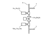
図1及び図2は給水設備を実施する形態の一例で、立て向きの給水主管に複数の減圧弁を設けた減圧弁直列方式の場合を示している。斯かる減圧弁直列方式は高層ビルに適している。図中、1は受水槽、2は受水槽1の上方に設置された高置水槽、3は受水槽1の水を高置水槽2に揚水するための揚水管、4は揚水管3に設けられた揚水ポンプ、5は高置水槽2の底面に接続された横引き管、6は立て向きに敷設した給水主管であり、横引き管5の一端は給水主管6の上端近傍に接続されている。
【0028】
7は給水主管6の立て方向へ所定の間隔で、建物の階層に対応して接続された複数の給水管であり、給水管7には、図示してないが給水のためにフラッシュ弁等のバルブが接続されている。8a,8b,8cは所定の上下2本の給水管7の間に位置するよう、給水主管6の中途部に接続された複数の減圧弁、9a,9b,9c,10a,10b,10cは減圧弁8を挟んで対向するよう、所定の上下2本の給水管7の間において給水主管6に接続されたショックアブソーバである。
【0029】
減圧弁8a,8b,8cは図5〜図7の減圧弁gと同一構造で従来周知のものであり、二次側の水圧が設定圧力になるよう予めばね力が調整されている。
【0030】
又、ショックアブソーバ9a,9b,9c,10a,10b,10cも従来周知の構造のもので、例えばケーシング内部に収納したゴム袋内にプレチャージ空気が封入されたエアバッグ型等がある。ケーシング内部には、給水主管6からの水を蓄え得るようになっており、且つ、ケーシングからは蓄えられた水を封入されたガスの圧力により給水主管6内に導入し得るようになっている。
【0031】
而して、給水時におけるフラッシュ弁等のバルブの急開時には、減圧弁8a,8b,8cに作動遅れがあり、減圧弁8a,8b,8cの二次側に水柱分離現象による負圧の空間が生じようとしても、ショックアブソーバ10a,10b,10cに蓄えられていた水を二次側に導入することにより、減圧弁8a,8b,8cの二次側における給水主管6内に水柱分離現象が生じるのを防止し、ウォータハンマが発生しないようになっている。
【0032】
又、フラッシュ弁等のバルブの急閉止時には、そのときに生じる水の衝撃圧力をショックアブソーバ10a,10b,10cに吸収すると共に、減圧弁8a,8b,8cが閉止するまでに作動遅れがあり、そのときに生じる水の衝撃圧力が減圧弁8a,8b,8cを二次側から一次側に流通した場合に、この流通した水の衝撃圧力をショックアブソーバ9a,9b,9cにより吸収し、ウォータハンマを防止し得るようになっている。
【0033】
更に、減圧弁8a,8b,8cが開き、給水主管6の減圧弁8a,8b,8cよりも上方の部分を水が流下する場合には、ショックアブソーバ9a,9b,9cに蓄えられていた水は、給水主管6に導入されるようになっている。
【0034】
11は給水主管6の頂部に接続された給排気弁であり、横引き管5が長い場合に給水管7に接続されたフラッシュ弁等のバルブが開いた際に、給水主管6の上部に水柱分離現象が生じることを防いで、高置水槽2からの水が給水主管6内に激しく流下するのを防止し、ウォータハンマが発生するのを防止し得るようになっている。
【0035】
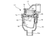
給排気弁11の詳細は図3、図4に示されている。図中、12は内部が中空のケーシングであり、ケーシング12は下端に給水主管6の頂部に対する接続用口12aを備えており、上端部は開放されている。
【0036】
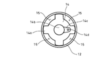
ケーシング12内にはコイルばね13が収納され、コイルばね13の上端には、ケーシング12内の上端部に収納されるようにした円板状のばね受け14が支持されている。ばね受け14の外周には、円周方向へ所定の間隔で、ケーシング12の内周壁に案内されるようにした突出部14aが形成されている。而して、ばね受け14の外周面及び隣合う突出部14a並びにケーシング12の内周壁面に包囲された空間により、給気用の空隙15が形成されている。
【0037】
ばね受け14の上面には円形の凹部14bが形成され、凹部14bには、ばね受け14の径方向外方へ向け延在する凹溝14cが連通されている。又、ばね受け14には上下に貫通する排気孔14dが穿設され、排気孔14dは凹溝14cに対し開口している。
【0038】
ケーシング12の上端には、ばね受け14の上面を押え得るよう、上下に貫通する中空筒状の蓋16が螺合されており、蓋16には、90度エルボ状のキャップ17が外嵌されている。
【0039】
ケーシング12内には、フロート弁18が収納され、フロート弁18は、排気孔14dよりも僅かにばね受け14の径方向外方に位置してケーシング12内へ延在するようばね受け14に固設したガイド19によってガイドされるようになっている。なお、図中、20はばね受け14の上面に当接し得るよう蓋16のばね受け14に対する対向面に設けたOリングである。
【0040】
次に、上記図示例の作動を説明する。
高置水槽2から給水を行う場合には、受水槽1に受水されている水は、予め揚水ポンプ4により揚水管3を介し高置水槽2に貯留されている。
【0041】
例えば、給水主管6における最上部の減圧弁8aよりも上部に接続された所定の給水管7に設けたフラッシュ弁等のバルブを開くと、水は当該バルブから流出して減圧弁8aの位置よりも上の所定の階層で給水が行われる。当該バルブを閉止すると給水は停止される。
【0042】
給水主管6の減圧弁8a,8bとの間の部分に接続された所定の給水管7に設けたフラッシュ弁等のバルブを開くと、先ず減圧弁8aの二次側において、水は給水主管6、給水管7を経て当該フラッシュ弁等のバルブから流出し、減圧弁8a,8bの間の所定の階層で給水が開始され、次いで一次側と二次側の圧力差により減圧弁8aが開いて減圧弁8a上方の給水主管6内の水は減圧弁8aの一次側から二次側に流下する。
【0043】
而して、減圧弁8aの二次側に流下した所定の圧力の水は給水主管6、所定の給水管7を経てフラッシュ弁等のバルブから流出し、減圧弁8a,8bの間の所定の階層で給水が行われる。又、当該バルブを閉止すると、減圧弁8aは閉止して給水は停止される。
【0044】
給水主管6の減圧弁8b,8cとの間の部分に接続された所定の給水管7に設けたフラッシュ弁等のバルブを開くと、先ず減圧弁8bの二次側において、水は給水主管6、所定の給水管7を経て当該フラッシュ弁等のバルブから流出し、給水が開始され、次いで一次側と二次側の圧力差により減圧弁8bが開いて減圧弁8bよりも上方の給水主管6内の水は減圧弁8bの一次側から二次側に流下し、続いて一次側と二次側の圧力差により減圧弁8aが開いて減圧弁8a上方の給水主管6内の水は減圧弁8aの一次側から二次側に流下し、更に減圧弁8bを一次側から二次側に流下する。
【0045】
而して、減圧弁8bの二次側へ流下した所定の圧力の水は、所定の給水管7を経てフラッシュ弁等のバルブから流出し、減圧弁8b,8cの間の所定の階層で給水が行われる。又当該バルブを閉止すると、減圧弁8b,8aは順次閉止して給水は停止される。
【0046】
給水主管6の減圧弁8cよりも下方の部分に接続された所定の給水管7に設けたフラッシュ弁等のバルブを開くと、先ず減圧弁8cの二次側において、水は給水主管6、所定の給水管7を経て当該フラッシュ弁等のバルブから流出し、給水が開始され、次いで一次側と二次側の圧力差により減圧弁8cが開いて減圧弁8cよりも上方の給水主管6内の水は減圧弁8cの一次側から二次側に流下し、続いて一次側と二次側の圧力差により減圧弁8bが開いて減圧弁8b上方の給水主管6内の水は減圧弁8bの一次側から二次側に流下し、次いで減圧弁8cの一次側から二次側に流下し、更に、一次側と二次側の圧力差により減圧弁8aが開いて減圧弁8a上方の給水主管6内の水は減圧弁8aの一次側から二次側に流下し、次いで減圧弁8bの一次側から二次側に流下し、続いて減圧弁8cの一次側から二次側に流下する。
【0047】
而して減圧弁8cの二次側へ流下した所定の圧力の水は、所定の給水管7を経て当該フラッシュ弁等のバルブから流出し、減圧弁8cよりも下方の所定の階層で給水が行われる。又、当該バルブを閉止すると、減圧弁8c,8b,8aは順次閉止して給水は停止される。
【0048】
図1の図示例においては、フラッシュ弁等のバルブを開くことにより、減圧弁8a,8b,8cの二次側(図1では減圧弁8a,8b,8cの下側)において急激に下流へ給水が行われると、減圧弁8a,8b,8cが開いて水が流通するまでタイムラグが発生するため、減圧弁8a,8b,8cの二次側において給水主管6内に真空の空間が形成される水柱分離現象が生じようとすることがある。
【0049】
しかるに、本図示例では、減圧弁8a,8b,8cの二次側にショックアブソーバ10a,10b,10cが設けられており、ショックアブソーバ10a,10b,10cには水が蓄圧状態で蓄えられているため、減圧弁8a,8b,8cの二次側の水がフラッシュ弁等のバルブから急激に給水されても、ショックアブソーバ10a,10b,10cに蓄えられていた水が減圧弁8a,8b,8cの二次側に導入され、その結果、減圧弁8a,8b,8cの二次側に水柱分離現象が生じることはない。
【0050】
なお、減圧弁8a,8b,8cが開いた後は、ショックアブソーバ9a,9b,9cに蓄圧されている水も給水主管6へ導入される。
【0051】
上述のように、減圧弁8a,8b,8cの二次側には水柱分離現象が生じることがないため、フラッシュ弁等のバルブを急開した際に水が高置水槽2内から給水主管6内を経て減圧弁8a,8b,8c側に激しく流下することはない。従って、給水主管6内の水が給水主管6に激しくぶつかることはなく、ウォータハンマが発生することはない。
【0052】
フラッシュ弁等のバルブが急閉止された際には減圧弁8a,8b,8cの二次側においては、水の衝撃圧力はショックアブソーバ10a,10b,10cに蓄えられる。又、減圧弁8a,8b,8cが閉止するのにタイムラグが発生するため、水の一部は減圧弁8a,8b,8cの二次側から一次側に漏出するが、この水の衝撃圧力はショックアブソーバ9a,9b,9cに蓄えられる。従って、フラッシュ弁等のバルブの急閉時にもウォータハンマが発生することはない。
【0053】
又、横引き管5が長いと、フラッシュ弁等のバルブが開かれて高置水槽2から給水が行われる際に、横引き管5内での水の流速と給水主管6内の水の流速の差により給水主管6内上部に水柱分離現象が生じ、負圧の空間が形成されることがある。而して、この場合には、図3に示すばね受け14が、コイルばね13の抗力に打ち勝ち、外気と負圧の圧力差で下降し(この場合フロート弁18もばね受け14に接触した状態で押されて下降する)、蓋16のOリング20取り付け面とばね受け14との間には隙間ができる。
【0054】
このため、大気は、キャップ17、蓋16の中空部、蓋16のOリング20取り付け面とばね受け14との間に形成された隙間、空隙15を経てケーシング12内に流入し、水柱分離現象の生じた空間部に導入されて負圧が解消される。従って、フラッシュ弁等のバルブが閉止された場合でも、高置水槽2内の水は急激に横引き管5を経て給水主管6上部の空気の閉じ込められた空間部に流入することはなく、ゆっくりと流入することになる。このため、横引き管5や給水主管6にウォータハンマが生じることを防止することができる。
【0055】
給水主管6の上部及び給排気弁11のケーシング12内に空気が流入すると、フロート弁18には水による浮力が作用しない状態となる。このため、フロート弁18は、重力により図3の仮想線に示すようにガイド19の上端を支点として傾き、ばね受け14下面と、フロート弁18上面との間に隙間が形成されて排気孔14dの下端が開口される。従って、給水主管6上部に閉じ込められた空気は、高置水槽2から除々に流入する水に押され、ケーシング12内空間、排気孔14dを経て蓋16の中空部に排出され、蓋16からキャップ17を経て外部へ排出される。
【0056】
給水主管6上部及びケーシング12内に高置水槽2からの水が充水されると、フロート弁18は浮力により傾斜状態を解除されて図3の実線状態に戻る。従って、フロート弁18の上面により排気孔14dは閉止され、給水主管6からの空気抜きは終了する。
【0057】
なお、本発明の給水設備は、上述の図示例にのみ限定されるものではなく、本発明の要旨を逸脱しない範囲内において種々変更を加え得ることは勿論である。
【0058】
【発明の効果】
以上、説明したように本発明の請求項1〜3記載の給水設備によれば、給水系統にウォータハンマが発生するを防止することができ、従って、騒音や振動を防止することができ、且つ水栓・器具等の使用に支障を来たすことがなく、しかも水栓や弁等の部品が摩耗せず、部品の寿命が長期化するという優れた効果を奏し得る。
【図面の簡単な説明】
【図1】本発明の給水設備の実施の形態の一例の概要を示す側面図である。
【図2】図1の減圧弁及びショックアブソーバの部分の拡大図である。
【図3】図1に示す吸排気弁の詳細図である。
【図4】図3に示す吸排気弁のばね受けの部分の平面図である。
【図5】従来の給水設備の一例の概要を示す側面図である。
【図6】従来の給水設備の他の例の概要を示す側面図である。
【図7】従来の給水設備の更に他の例の概要を示す側面図である。
【符号の説明】
2 高置水槽(水槽)
5 横引き管
6 給水主管
7 給水管
8a 減圧弁
8b 減圧弁
8c 減圧弁
9a ショックアブソーバ(衝撃吸収手段)
9b ショックアブソーバ(衝撃吸収手段)
9c ショックアブソーバ(衝撃吸収手段)
10a ショックアブソーバ(衝撃吸収手段)
10b ショックアブソーバ(衝撃吸収手段)
10c ショックアブソーバ(衝撃吸収手段)
11 吸排気弁[0001]
BACKGROUND OF THE INVENTION
The present invention relates to a water supply facility.
[0002]
[Prior art]
When water is supplied in a building such as a super high-rise building, if the water supply system is one system, the water supply pressure in the water supply main pipe is excessive on the lower floor. For this reason, when a valve such as a flush valve provided in the water supply system is suddenly opened or closed, a water hammer may occur, causing noise or vibration, impeding the use of a faucet or instrument, Wear of parts such as valves will become severe, and the service life will be shortened. For this reason, when the feed water pressure becomes higher than a predetermined value, it is necessary to adjust the feed water pressure by installing a pressure reducing valve or the like for the lower floor, for example.
[0003]
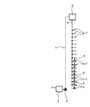
The water supply equipment shown in FIGS. 5 to 7 shows an example of zoning in which there is one water supply system and the pressure of the water supply is suppressed by a pressure reducing valve. FIG. 5 shows a main pipe depressurization method, in which a is a water receiving tank, b is a high water tank installed above the water receiving tank a, and c is a pump for pumping water from the water receiving tank a to the high water tank b. The pipe, d is a pumping pump provided in the pumping pipe c, e is a water supply main pipe connected to the bottom surface of the elevated water tank b, f is a predetermined interval in the standing direction of the water supply main pipe e, and corresponds to the building hierarchy A plurality of connected water supply pipes and g are pressure reducing valves connected to predetermined positions in the middle of the water supply main pipe e. Although not shown, a valve such as a flush valve is connected to the water supply pipe f as a water supply valve.
[0004]
When water is supplied from the elevated water tank b, the water received in the water receiving tank a is stored in advance in the elevated water tank b through the pumping pipe c by the pumping pump d.
[0005]
For example, when a valve such as a flush valve connected to a predetermined water supply pipe f above the pressure reducing valve g is opened, water flows out of the valve and water is supplied on a higher floor than the position of the pressure reducing valve g.
[0006]
Even when a valve such as a flush valve connected to a predetermined water supply pipe f below the pressure reducing valve g is opened, water flows out of the valve and water supply is started at a lower floor than the position of the pressure reducing valve g. . Further, in this case, since the spring force of the pressure reducing valve g is adjusted in advance so that the water pressure on the secondary side becomes the set pressure, a flush valve or the like connected to a predetermined water supply pipe f below the pressure reducing valve g is used. When the valve is opened and water supply is started, the water in the portion (primary side) above the pressure reducing valve g in the water supply main pipe e is reduced to a predetermined pressure by the pressure reducing valve g, and the water supplied below the pressure reducing valve g (secondary side) The water flows down into the main pipe e, and water is supplied from a valve such as a flush valve through a predetermined water supply pipe f.
[0007]
FIG. 6 shows each floor decompression system. In the figure, the same components as those shown in FIG. Thus, in each floor pressure reducing system, the pressure reducing valve g is not provided in the water supply main pipe e, but is provided in each water supply pipe f on a lower floor than the predetermined floor.
[0008]
In FIG. 6, the state in which water is supplied from the water supply pipe f not provided with the pressure reducing valve g is the same as the case where water is supplied from the water supply pipe f above the pressure reducing valve g of the main pipe pressure reducing system in FIG. .
[0009]
When a valve such as a flush valve connected to a water supply pipe f provided with a pressure reducing valve g is opened, water flows out of the valve and water supply is started. Since the spring pressure of the pressure reducing valve g is adjusted in advance so that the water pressure on the secondary side becomes the set pressure, a valve such as a flash valve connected to a predetermined water supply pipe f provided with the pressure reducing valve g is opened to supply water. Is started, the water upstream (primary side) of the pressure reducing valve g is reduced to a predetermined pressure by the pressure reducing valve g and flows into the water supply pipe f downstream (secondary side) of the pressure reducing valve g. Water is supplied from.
[0010]
FIG. 7 shows a group high pressure system, in which the same components as those shown in FIGS. 5 and 6 are given the same reference numerals. Thus, in the group high-pressure system, not all the water supply pipes f below the predetermined floor are provided with the pressure reducing valves g, but one water pipe f for each of the plurality of floors below the predetermined floor. A plurality of water supply pipes f ′ (three in the illustrated example) are provided by branching the water supply pipes f corresponding to the respective levels, and the pressure reducing valve g is provided in the water supply pipe f.
[0011]
In FIG. 7, the state at the time of water supply from the water supply pipe f in which the pressure reducing valve g is not provided is the same as the case of each floor pressure reducing system in FIG.
[0012]
When a valve such as a flush valve of the water supply pipe f ′ connected to the water supply pipe f provided with the pressure reducing valve g is opened, water flows out of the valve and water supply is started. Since the spring force of the pressure reducing valve g is adjusted in advance so that the water pressure on the secondary side becomes the set pressure, when the water supply pipe f provided with the pressure reducing valve g opens a valve such as a flush valve, Water upstream from the valve g (primary side) is depressurized to a predetermined pressure by the pressure reducing valve g, flows into the water supply pipes f and f ′ downstream (secondary side) of the pressure reducing valve g, and is supplied from a valve such as a flush valve. Is done.
[0013]
[Problems to be solved by the invention]
As shown in FIG. 5, in the case of a water supply facility in which a pressure reducing valve g is provided in a water supply main pipe e, a valve such as a flush valve of the water supply pipe f connected to the water supply main pipe e is opened upstream from the pressure reducing valve g. However, the water column separation phenomenon does not occur in the water supply main pipe e above the pressure reducing valve g. For this reason, there is no possibility that water hammer occurs in the water supply main pipe e above the pressure reducing valve g due to the sudden opening of the valve.
[0014]
6 and 7, in the case of a water supply facility provided with a pressure reducing valve g in the water supply pipe f, the water column separation phenomenon does not occur in the water supply main pipe e even if the valve such as the flush valve is opened rapidly. Therefore, there is no possibility that water hammer occurs in the water supply main pipe e due to the rapid opening of a valve such as a flush valve.
[0015]
However, in the case of a water supply facility in which a pressure reducing valve g is provided in the water supply main pipe e as shown in FIG. When water below the valve g (secondary side) is suddenly supplied, due to the structural characteristics of the pressure reducing valve g, a time lag occurs until the pressure reducing valve g opens and water flows from the primary side to the secondary side. To do.
[0016]
Therefore, on the secondary side of the pressure reducing valve g (below the pressure reducing valve g in FIG. 5), a water column separation phenomenon occurs in the water supply main pipe e to create a space, and this space portion has a negative pressure. Therefore, when the pressure reducing valve g is opened and water is supplied through the pressure reducing valve g, the water above the space portion suddenly falls into the space portion, and as a result, the water collides violently with the water supply main pipe e and water hammer is generated. There is a fear.
[0017]
Further, in the case of a water supply facility provided with a pressure reducing valve g in the water supply pipe f as shown in FIG. 6, water hammer does not occur in the water supply main pipe e, but water is supplied from each pressure reducing valve g to a valve such as a flash valve. If the distance of the pipe f is long, a vacuum space may occur in the water supply pipe f due to the water column separation phenomenon on the secondary side of the pressure reducing valve g, and the pressure reducing valve g opens to flow from the primary side to the secondary side. Therefore, when water is supplied through the pressure reducing valve g by sudden opening of a valve such as a flush valve, the water in the water supply main pipe e flows into the space vigorously and collides with the water supply pipe f. There is a risk of water hammer.
[0018]
Further, in the case of a water supply system in which a pressure reducing valve g is provided in the water supply pipe f as shown in FIG. 7, no water hammer is generated in the water supply main pipe e, but on the secondary side of each pressure reducing valve g, FIG. Similarly to the case, if the distance between the water supply pipes f and f ′ from the pressure reducing valve g to the valve such as the flush valve is long, a water column separation phenomenon may occur in the water supply pipes f and f ′ on the secondary side of the pressure reducing valve g. As a result, when water is supplied through the pressure reducing valve g due to sudden opening of a valve such as a flush valve, water in the water supply main pipe e flows into the space violently and collides with the water supply pipe f. May occur.
[0019]
Also, in the water supply equipment of FIGS. 5 to 7, when a valve such as a flush valve is suddenly closed, there is a risk that water hammer will occur in the water supply main pipe e and the water supply pipe f. The water hammer at the time of sudden closing of the valve such as the flush valve can be prevented by providing a commercially available water hammer prevention device in the vicinity of the flush valve or the like provided in the water supply pipe f or f ′. The passing pressure wave (water hammer) cannot be prevented. In addition, a water hammer prevention device provided in the vicinity of a valve such as a flush valve cannot prevent a water hammer due to a water faucet separation phenomenon on the secondary side of the pressure reducing valve g when the valve such as a flush valve is suddenly opened.
[0020]
The present invention has been made in view of the above-mentioned circumstances, and has an object to provide a water supply facility in which water hammer is not generated when a valve such as a flash valve is suddenly opened or closed. It is.
[0021]
[Means for Solving the Problems]
The water supply facility according to claim 1 is a vertical water supply pipe through which water from the water tank flows down, and a plurality of water supply pipes connected to the water supply main pipe at a predetermined interval in the vertical direction and provided with water supply valves . A pressure reducing valve provided in the water supply main pipe so as to be positioned between a predetermined water supply pipe and another water supply pipe disposed immediately above or directly below the water supply pipe among the plurality of water supply pipes; The water supply main pipe is disposed so as to face the valve, and is located between the predetermined water supply pipe and another water supply pipe arranged directly above or below the water supply pipe . And an impact absorbing means.
[0022]
Water supply according to claim 2 is obtained by the combination of the pressure reducing valve and the shock absorbing means and a plurality of sets.
[0023]
Water supply according to
[0024]
In the water supply facility of the present invention, when water is supplied with the water supply valve opened, the water accumulated in the shock absorbing means is supplied to the secondary side of the pressure reducing valve. Therefore, it is possible to prevent water hammer from occurring when the water supply valve is suddenly opened.
[0025]
Further, when the water supply valve is closed quickly, the impact of water is absorbed by the impact absorbing means provided before and after the pressure reducing valve, thereby preventing the water hammer from being generated.
[0026]
In addition, because the horizontal pipe is long, when the water supply valve is opened and water is supplied during water supply, if a water column separation phenomenon occurs in the upper part of the water supply main pipe and a vacuum space is formed, the intake / exhaust valve Opens and the atmosphere is introduced into the space. For this reason, the water in the water tank connected to the horizontal pulling pipe does not flow into the space portion suddenly, and therefore it is possible to prevent the water hammer from occurring.
[0027]
DETAILED DESCRIPTION OF THE INVENTION
Hereinafter, embodiments of the present invention will be described with reference to the drawings.
1 and 2 show an example of an embodiment for implementing a water supply facility, and shows a case of a pressure reducing valve series system in which a plurality of pressure reducing valves are provided in a standing water supply main pipe. Such a pressure reducing valve series system is suitable for high-rise buildings. In the figure, 1 is a water receiving tank, 2 is an elevated water tank installed above the
[0028]
[0029]
The
[0030]
The
[0031]
Thus, when a valve such as a flush valve is suddenly opened during water supply, there is a delay in operation of the
[0032]
Further, when a valve such as a flush valve is suddenly closed, the shock pressure of water generated at that time is absorbed by the
[0033]
Further, when the
[0034]
[0035]
Details of the air supply /
[0036]
A
[0037]
A circular recess 14b is formed on the upper surface of the
[0038]
A hollow
[0039]
A
[0040]
Next, the operation of the illustrated example will be described.
When water is supplied from the elevated water tank 2, the water received in the water receiving tank 1 is stored in the elevated water tank 2 by the
[0041]
For example, when a valve such as a flush valve provided in a predetermined
[0042]
When a valve such as a flush valve provided in a predetermined
[0043]
Thus, water having a predetermined pressure flowing down to the secondary side of the
[0044]
When a valve such as a flush valve provided in a predetermined
[0045]
Thus, water having a predetermined pressure flowing down to the secondary side of the
[0046]
When a valve such as a flash valve provided in a predetermined
[0047]
Thus, water having a predetermined pressure flowing down to the secondary side of the
[0048]
In the illustrated example of FIG. 1, by supplying a valve such as a flush valve, water is rapidly supplied downstream on the secondary side of the
[0049]
However, in the illustrated example,
[0050]
In addition, after the
[0051]
As described above, since the water column separation phenomenon does not occur on the secondary side of the
[0052]
When a valve such as a flash valve is suddenly closed, the impact pressure of water is stored in the
[0053]
If the
[0054]
For this reason, the air flows into the
[0055]
When air flows into the upper part of the water supply
[0056]
When the water supply
[0057]
In addition, the water supply equipment of the present invention is not limited to the illustrated examples described above, and it is needless to say that various changes can be made without departing from the scope of the present invention.
[0058]
【The invention's effect】
As described above, according to the water supply equipment according to claims 1 to 3 of the present invention, it is possible to prevent the water hammer from being generated in the water supply system, and therefore it is possible to prevent noise and vibration, and There is no hindrance to the use of the faucet / equipment and the like, and the components such as the faucet and the valve are not worn, and an excellent effect of prolonging the life of the component can be obtained.
[Brief description of the drawings]
FIG. 1 is a side view showing an outline of an example of an embodiment of a water supply facility of the present invention.
FIG. 2 is an enlarged view of a pressure reducing valve and a shock absorber portion of FIG. 1;
FIG. 3 is a detailed view of the intake / exhaust valve shown in FIG. 1;
4 is a plan view of a portion of a spring receiver of the intake / exhaust valve shown in FIG. 3. FIG.
FIG. 5 is a side view showing an outline of an example of a conventional water supply facility.
FIG. 6 is a side view showing an outline of another example of conventional water supply equipment.
FIG. 7 is a side view showing an outline of still another example of a conventional water supply facility.
[Explanation of symbols]
2 Elevated water tank (water tank)
5
9b Shock absorber (Shock absorbing means)
9c Shock absorber (Shock absorbing means)
10a Shock absorber (Shock absorbing means)
10b Shock absorber (Shock absorbing means)
10c Shock absorber (Shock absorbing means)
11 Intake and exhaust valves
Claims (3)
Priority Applications (1)
| Application Number | Priority Date | Filing Date | Title |
|---|---|---|---|
| JP2002248773A JP4064183B2 (en) | 2002-08-28 | 2002-08-28 | Water supply equipment |
Applications Claiming Priority (1)
| Application Number | Priority Date | Filing Date | Title |
|---|---|---|---|
| JP2002248773A JP4064183B2 (en) | 2002-08-28 | 2002-08-28 | Water supply equipment |
Publications (2)
| Publication Number | Publication Date |
|---|---|
| JP2004084371A JP2004084371A (en) | 2004-03-18 |
| JP4064183B2 true JP4064183B2 (en) | 2008-03-19 |
Family
ID=32056069
Family Applications (1)
| Application Number | Title | Priority Date | Filing Date |
|---|---|---|---|
| JP2002248773A Expired - Lifetime JP4064183B2 (en) | 2002-08-28 | 2002-08-28 | Water supply equipment |
Country Status (1)
| Country | Link |
|---|---|
| JP (1) | JP4064183B2 (en) |
Families Citing this family (4)
| Publication number | Priority date | Publication date | Assignee | Title |
|---|---|---|---|---|
| JP5642638B2 (en) * | 2011-09-01 | 2014-12-17 | 能美防災株式会社 | Sprinkler fire extinguishing equipment and control method thereof |
| CN103669489B (en) * | 2013-05-09 | 2016-05-18 | 上海沥源流体科技有限公司 | Roof tank water quality controller |
| CN107152582A (en) * | 2017-06-30 | 2017-09-12 | 华蓝设计(集团)有限公司 | Super high-rise dwelling house feed pipe noise reduction system |
| JP7124175B1 (en) * | 2021-06-16 | 2022-08-23 | 野村マイクロ・サイエンス株式会社 | Liquid recovery system, liquid supply system, and pressure regulation method |
-
2002
- 2002-08-28 JP JP2002248773A patent/JP4064183B2/en not_active Expired - Lifetime
Also Published As
| Publication number | Publication date |
|---|---|
| JP2004084371A (en) | 2004-03-18 |
Similar Documents
| Publication | Publication Date | Title |
|---|---|---|
| AU2009220860B2 (en) | An air release valve | |
| US5511577A (en) | Air release valve | |
| JPH09287533A (en) | Fuel tank gas exhaust system | |
| JP4064183B2 (en) | Water supply equipment | |
| JP2001132862A (en) | Air valve | |
| JP6916967B2 (en) | Discharge valve unit and fluid equipment | |
| KR20210102564A (en) | a reducing structure of water hammer-arrester for the grooved joint | |
| JP7368826B2 (en) | valve device | |
| US20040107992A1 (en) | Air release valve | |
| CN210484702U (en) | Bivalve axial-flow type check valve | |
| KR200390712Y1 (en) | Low of water pressure high speed air valve | |
| KR20210098603A (en) | a structure for water hammer-arrester | |
| KR20210098604A (en) | a structure of water hammer-arrester for the grooved joint | |
| KR102898043B1 (en) | Water hammer preventer manufacturing method | |
| JPH0545898Y2 (en) | ||
| JP2021025619A (en) | Valve device | |
| KR100303475B1 (en) | Gas flow shutoff valve in case of gas leakage | |
| JP3349531B2 (en) | Liquid level control device for storage tank | |
| JPWO1998045631A1 (en) | Intake and exhaust valves | |
| JPH0579229U (en) | Seal pot | |
| JPS59113383A (en) | Quick suction air valve with exhaust quantity control valve | |
| KR200327577Y1 (en) | Inhalation discharge valve | |
| JPH0619887Y2 (en) | Air valve | |
| JP6779065B2 (en) | Air valve | |
| JPH06313566A (en) | Air separator for water hammer prevention |
Legal Events
| Date | Code | Title | Description |
|---|---|---|---|
| A621 | Written request for application examination |
Free format text: JAPANESE INTERMEDIATE CODE: A621 Effective date: 20050624 |
|
| A977 | Report on retrieval |
Free format text: JAPANESE INTERMEDIATE CODE: A971007 Effective date: 20070221 |
|
| A131 | Notification of reasons for refusal |
Free format text: JAPANESE INTERMEDIATE CODE: A131 Effective date: 20070227 |
|
| A521 | Request for written amendment filed |
Free format text: JAPANESE INTERMEDIATE CODE: A523 Effective date: 20070427 |
|
| TRDD | Decision of grant or rejection written | ||
| A01 | Written decision to grant a patent or to grant a registration (utility model) |
Free format text: JAPANESE INTERMEDIATE CODE: A01 Effective date: 20071204 |
|
| A61 | First payment of annual fees (during grant procedure) |
Free format text: JAPANESE INTERMEDIATE CODE: A61 Effective date: 20071226 |
|
| R150 | Certificate of patent or registration of utility model |
Free format text: JAPANESE INTERMEDIATE CODE: R150 Ref document number: 4064183 Country of ref document: JP Free format text: JAPANESE INTERMEDIATE CODE: R150 |
|
| FPAY | Renewal fee payment (event date is renewal date of database) |
Free format text: PAYMENT UNTIL: 20110111 Year of fee payment: 3 |
|
| FPAY | Renewal fee payment (event date is renewal date of database) |
Free format text: PAYMENT UNTIL: 20120111 Year of fee payment: 4 |
|
| R250 | Receipt of annual fees |
Free format text: JAPANESE INTERMEDIATE CODE: R250 |
|
| FPAY | Renewal fee payment (event date is renewal date of database) |
Free format text: PAYMENT UNTIL: 20130111 Year of fee payment: 5 |
|
| R250 | Receipt of annual fees |
Free format text: JAPANESE INTERMEDIATE CODE: R250 |
|
| FPAY | Renewal fee payment (event date is renewal date of database) |
Free format text: PAYMENT UNTIL: 20130111 Year of fee payment: 5 |
|
| S531 | Written request for registration of change of domicile |
Free format text: JAPANESE INTERMEDIATE CODE: R313531 |
|
| FPAY | Renewal fee payment (event date is renewal date of database) |
Free format text: PAYMENT UNTIL: 20130111 Year of fee payment: 5 |
|
| R350 | Written notification of registration of transfer |
Free format text: JAPANESE INTERMEDIATE CODE: R350 |
|
| FPAY | Renewal fee payment (event date is renewal date of database) |
Free format text: PAYMENT UNTIL: 20140111 Year of fee payment: 6 |
|
| R250 | Receipt of annual fees |
Free format text: JAPANESE INTERMEDIATE CODE: R250 |
|
| R250 | Receipt of annual fees |
Free format text: JAPANESE INTERMEDIATE CODE: R250 |
|
| R250 | Receipt of annual fees |
Free format text: JAPANESE INTERMEDIATE CODE: R250 |
|
| R250 | Receipt of annual fees |
Free format text: JAPANESE INTERMEDIATE CODE: R250 |
|
| R250 | Receipt of annual fees |
Free format text: JAPANESE INTERMEDIATE CODE: R250 |
|
| R250 | Receipt of annual fees |
Free format text: JAPANESE INTERMEDIATE CODE: R250 |
|
| R250 | Receipt of annual fees |
Free format text: JAPANESE INTERMEDIATE CODE: R250 |
|
| R250 | Receipt of annual fees |
Free format text: JAPANESE INTERMEDIATE CODE: R250 |
|
| R250 | Receipt of annual fees |
Free format text: JAPANESE INTERMEDIATE CODE: R250 |
|
| EXPY | Cancellation because of completion of term |