JP4064532B2 - Steam turbine outer casing cooling structure - Google Patents
Steam turbine outer casing cooling structure Download PDFInfo
- Publication number
- JP4064532B2 JP4064532B2 JP15754798A JP15754798A JP4064532B2 JP 4064532 B2 JP4064532 B2 JP 4064532B2 JP 15754798 A JP15754798 A JP 15754798A JP 15754798 A JP15754798 A JP 15754798A JP 4064532 B2 JP4064532 B2 JP 4064532B2
- Authority
- JP
- Japan
- Prior art keywords
- steam
- outer casing
- space
- pressure turbine
- turbine section
- Prior art date
- Legal status (The legal status is an assumption and is not a legal conclusion. Google has not performed a legal analysis and makes no representation as to the accuracy of the status listed.)
- Expired - Lifetime
Links
- 238000001816 cooling Methods 0.000 title claims description 20
- 230000001105 regulatory effect Effects 0.000 claims description 3
- 238000000638 solvent extraction Methods 0.000 claims description 2
- 230000008646 thermal stress Effects 0.000 description 6
- 238000010586 diagram Methods 0.000 description 2
- 238000010438 heat treatment Methods 0.000 description 2
- 230000000717 retained effect Effects 0.000 description 2
- 230000000694 effects Effects 0.000 description 1
- 230000002093 peripheral effect Effects 0.000 description 1
Images


Landscapes
- Turbine Rotor Nozzle Sealing (AREA)
Description
【0001】
【発明の属する技術分野】
本発明は蒸気タービンの外車室冷却構造に関し、特に単車室型の蒸気タービンにおいて高圧蒸気のノズル室を有するダミーリングと外車室との間に形成される空間内に蒸気を流して冷却し、外車室の熱伸びの影響を抑えるような構造としたものである。
【0002】
【従来の技術】
図3は従来の単車室型の蒸気タービンの内部を示す断面図である。図において、1はロータであり、2はタービン全体を覆う外車室、3は静止側の静翼とロータに固定の動翼を多段に配置した高圧タービン部、4は同じく動翼と静翼とを多段に配置した中圧タービン部、5は同様に低圧タービン部である。これら高、中及び低圧タービン部3,4,5がロータ1の周囲軸方向で単一の外車室内に配置されている。
【0003】
6は高圧蒸気入口ポートで、高圧タービン部3へ高圧蒸気を供給するもの、7は高圧蒸気出口ポートで高圧タービン部3で仕事をした蒸気が流出する。8は中圧蒸気入口ポートで、中圧タービン部4へ中圧蒸気を供給するもの、9は低圧蒸気入口ポートで、低圧タービン部5へ低圧蒸気を供給するものである。10はダミーリングであり、高圧蒸気のノズル室13とノズルが一体に組込まれており、かつ高圧タービン部3と中圧タービン部4との間をシールし、区分するものである。11は中圧タービン部4と低圧タービン部5とで仕事を終えた蒸気が排気される排気室である。18はダミーリング10と外車室2とで形成される内部の空間である。
【0004】
上記構成の蒸気タービンにおいて、高圧蒸気30は高圧蒸気入口ポート6より高圧タービン部3に流入し、高圧タービン部3で仕事をして高圧蒸気出口ポート7から流出する。又、中圧蒸気32は中圧蒸気入口ポート8より中圧タービン部4に流入し、中圧タービン部4で仕事をし、その蒸気は更に低圧タービン部5へ流れる。又、低圧蒸気33は低圧蒸気入口ポート9より低圧タービン部5へ流入し、低圧タービン部5では中圧タービン部4からの蒸気と低圧蒸気入口ポート9から流入した蒸気とが一緒になって仕事をし、排気室11へ排出する。
【0005】
上記構成の蒸気タービンは前述のように高圧タービン部3、中圧タービン部4、低圧タービン部5でロータ1を回転させ、ロータ1に接続した発電機を回転させるが、ロータ1周囲には高圧タービン部3と中圧タービン部4との間をシールし、区分するダミーリング10が設けられており、ダミーリング10はノズル室13とノズルが一体的に組込まれており、ダミーリング10と外車室2との間には空間18が形成されている。この空間18はヒートチャンバとなっており、冷却蒸気等を流すような冷却構造は特に設けておらず、高圧タービン部3の蒸気通路へ流入する高圧蒸気により熱的影響を受けやすい構造であった。
【0006】
【発明が解決しようとする課題】
前述のように単車室内で高、中、低圧タービン部を構成する蒸気タービンにおいては、高圧タービン部3と中圧タービン部4との間をシールし、区分するためにダミーリング10が設けられており、このダミーリング10と外車室2との間には空間18が形成されている。この空間18はヒートチャンバとなっており、特に冷却構造が採用されておらず、高圧蒸気30の影響を受けて加熱される。高圧タービン部3には、前述のように高圧蒸気入口ポート6から高圧蒸気30がダミーリング10に一体的に形成されたノズル室13に入り、ノズルより蒸気通路へ流出するが、このノズル室13の蒸気温度は約560℃位の高温であり、その直後の蒸気通路は500℃程度となり、この高温蒸気によりダミーリング10の壁面を通して空間18内が加熱される。
【0007】
空間18は上記の加熱により480℃程度の高温となり、この空間18内は蒸気通路とダミーリング10端部の隙間を介して連通しているので、空間18に流入した蒸気は流動せず、よどんで滞留し、高温に加熱される。そのために外車室2の壁面はこの熱の影響を受け、大きな熱応力を受ける。従って上下の外車室を固定する両端フランジのボルトも大きなサイズのものが採用されている。
【0008】
そこで本発明は単車室内に高圧、中圧、低圧タービン部を配置した蒸気タービンにおいて、ダミーリングと外車室との間に形成される空間に蒸気を流動させるような対策を施し、外車室を冷却するような構造を提案し、外車室の熱伸びによる影響を抑えることを課題としてなされたものである。
【0009】
【課題を解決するための手段】
本発明は前述の課題を解決するために次の手段を提供する。
【0010】
単車室型の蒸気タービンの外車室内にロータに沿って高圧、中圧、低圧タービン部をそれぞれ配置し、前記高圧タービン部と中圧タービン部との間をシールし、区分するダミーリングをロータ周囲に配設し、同ダミーリングには高圧蒸気を導くノズル部を形成し同ノズル部を前記高圧タービン部の蒸気通路入口に連接すると共に、同ダミーリングが前記外車室との間に空間を形成してなる蒸気タービンにおいて、前記ダミーリングの端部は前記高圧タービン部の動翼出口部の外車室とで隙間を形成して前記空間と同動翼出口部とを連通し、この隙間を通じて上記動翼出口部からの蒸気の一部を前記空間の一端に導き、中圧タービン部側の同空間の他端から外車室に穿設された穴を通り、これに連通する流量調整弁を有する外部配管によって後段の同蒸気通路に戻すことで、同空間内を冷却することを特徴とする蒸気タービンの外車室冷却構造。
【0011】
単車室型の蒸気タービンの外車室内に高圧、中圧、低圧タービン部を配置した蒸気タービンでは高圧タービン部にはダミーリングに一体的に形成されたノズル部より高圧蒸気を導いており、ダミーリングと外車室との間には空間が形成されている。この空間はダミーリングの端部において高圧タービン部の蒸気通路から隙間を通って蒸気が流入するが、従来は空間に流入した蒸気は空間内部で流動せずによどんで滞留し、ダミーリングの壁面を介して高圧蒸気により加熱され、外車室を加熱し、外車室の熱伸びによる熱応力を高め、そのために上、下の外車室のフランジを締結するボルトも大きなものを使用して強度を高めていた。
【0012】
本発明の冷却構造は、空間内に高圧タービン部より流入する蒸気が空間内の端に連通する外部配管に流入するので、空間内では一端から流入する蒸気は他端に向って流れ、外部配管を通って高圧タービン部の蒸気通路に戻り、空間内を蒸気が流動する。従って空間内では加熱される温度よりも低温の蒸気で絶えず冷却され、その周囲の外車室の温度上昇を抑えることができる。これにより上、下外車室のフランジを締結しているボルトも従来よりも小さなサイズとすることができる。
【0013】
【発明の実施の形態】
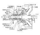
以下、本発明の実施の形態について図面に基づいて具体的に説明する。図1は本発明の実施の一形態に係る蒸気タービンの外車室冷却構造を示す構成図、図2はそのA部拡大詳細図である。図1において、符号1乃至11,13,30乃至33は図3に示す従来のものと同じであるので詳しい説明は省略し、そのまま引用して説明するが、本発明の特徴部分は20,21の部分であり、以下に詳しく説明する。
【0014】
図1、2において、外車室2とダミーリング10とで形成される空間18の中圧タービン部4側のX点には外部配管20の一端が連通しており、外部配管20の他端は高圧タービン部3の蒸気通路15の後段側に連通している。又、外部配管20の途中には流量調整弁21が設けられている。
【0015】
上記構成の外車室冷却構造において、高圧蒸気30は高圧蒸気入口ポート6よりタービンに流入し、ダミーリング10と一体的に形成されたノズル室13に入り、ノズル12より高圧タービン部3の蒸気通路15に流出して仕事をし、高圧排出蒸気31としてロータ1を駆動して高圧蒸気出口ポート7より外部へ流出する。
【0016】
外車室2とダミーリング10との間に形成される空間18は、ダミーリング10のノズル室13からノズル12を通り、高圧タービン部3の蒸気通路に流出する高圧蒸気によりダミーリング10の壁面10aを通して高温に加熱され、約480℃程度の高温となる。
【0017】
この空間18は後述するように高圧タービン部3の蒸気通路に隙間を介して連通しており、この隙間から蒸気が流入するが、この蒸気は従来は流動せずに流れがよどんで滞留し、この滞留した蒸気が前述の高圧蒸気で加熱され、外車室2の壁面がこれにより高温となって熱応力を発生していた。
【0018】
本実施の形態では空間18内には高圧タービン部3の蒸気通路より蒸気が流入するが、この蒸気はX点より外部配管20を通って流出し、外部配管20を通って流入点より後段の蒸気通路15内へY点より流出するので、外車室2とダミーリング10との間に形成された空間18内の蒸気は絶えず流動し、蒸気のよどみを生ずることなく空間18内を高圧蒸気30のノズル12近辺の温度よりも低温の蒸気で冷却し、外車室2の壁面の温度上昇を抑え、大きな熱応力の発生を防止する。
【0019】
図2は図1におけるA部の拡大詳細断面図であり、空間18内の蒸気の流れを示している。図において、高圧蒸気30はダミーリング10に一体的に形成されたノズル室13に入り、ノズル12より高圧タービン部3の蒸気通路15に流出する。流出した蒸気は静翼17、動翼16を多段に配置した蒸気通路15を流れて仕事をし、ロータ1を駆動する。
【0020】
ノズル室13の温度は約560℃位の高温であり、蒸気はノズル12より流して1段静翼17と1段動翼16に流入するがこの付近の温度は500℃位となり、ダミーリング10の壁面10aはこの温度で加熱され、空間18内はこの壁面10aを介して加熱される。
【0021】
空間18は高圧タービン部3の1段動翼16出口部の外車室2とダミーリング10端部とで形成される隙間19と連通しており、ここから動翼16を通過した蒸気の一部が流入する。この流入した蒸気は従来では空間18内によどんで滞留していたが、本発明ではその蒸気は空間18内を流れて外車室2のX点において貫通して穿設された穴22を通り、これに連通する外部配管20に流入する。
【0022】
外部配管20の他端は外車室2のY点において貫通して穿設された穴23に連通しており、従って外部配管20のX点は後流側のY点よりも蒸気圧力が高く、隙間19より空間18に流入した蒸気は外部配管20のY点から穴23を通り、低圧側の蒸気通路に容易に流出して戻される。
【0023】
又、外部配管20には流量調整弁21が設けてあり、流量を調整して外車室2の冷却を制御することができる。又、空間18内はノズル12から流出する直後の500℃程度の蒸気によりダミーリング10の壁面10aを介して加熱されるが、空間18内の蒸気は1段動翼16を出た蒸気で500℃よりも低温の蒸気であり、上記の流量調整弁21で流量を調整しながら、空間18内を効果的に冷却し、温度上昇を抑えることができる。
【0024】
以上、説明の実施の形態によれば、外車室2とダミーリング10との間に形成される空間18と高圧タービン部3の蒸気通路15とを連通する外部配管20を設け、空間18内に蒸気を流して空間18内を冷却し、外車室2の温度上昇を抑えるような冷却構造としたことにより、外車室2の加熱による熱応力を抑え、そのために上、下の外車室を連結するフランジのボルトを従来よりも小さくすることができる。
【0025】
【発明の効果】
本発明の蒸気タービンの外車室冷却構造は、単車室型の蒸気タービンの外車室内にロータに沿って高圧、中圧、低圧タービン部をそれぞれ配置し、前記高圧タービン部と中圧タービン部との間をシールし、区分するダミーリングをロータ周囲に配設し、同ダミーリングには高圧蒸気を導くノズル部を形成し同ノズル部を前記高圧タービン部の蒸気通路入口に連接すると共に、同ダミーリングが前記外車室との間に空間を形成してなる蒸気タービンにおいて、前記ダミーリングの端部は前記高圧タービン部の動翼出口部の外車室とで隙間を形成して前記空間と同動翼出口部とを連通し、この隙間を通じて上記動翼出口部からの蒸気の一部を前記空間の一端に導き、中圧タービン部側の同空間の他端から外車室に穿設された穴を通り、これに連通する流量調整弁を有する外部配管によって後段の同蒸気通路に戻すことで、同空間内を冷却することを特徴としている。このような冷却構造により、空間内には外部配管により絶えず高圧タービン部からの蒸気通路入口より後段側の低温蒸気が流れ、流量調整弁で流量を調整しながら、空間内が効果的に冷却され、外車室の温度上昇を抑えることができるので、熱応力が抑えられ、外車室のフランジを締結するボルトのサイズも従来より小さくすることができる。又、これにより車室外部への蒸気もれに対する信頼性も向上する。
【図面の簡単な説明】
【図1】 本発明の実施の一形態に係る蒸気タービンの外車室冷却構造を示す構成図である。
【図2】 図1におけるA部拡大詳細断面図である。
【図3】 従来の単車室型の蒸気タービンの断面図である。
【符号の説明】
1 ロータ
2 外車室
3 高圧タービン部
4 中圧タービン部
5 低圧タービン部
6 高圧蒸気入口ポート
7 高圧蒸気出口ポート
8 中圧蒸気入口ポート
9 低圧蒸気入口ポート
10 ダミーリング
11 排気室
12 ノズル
13 ノズル室
15 蒸気通路
16 動翼
17 静翼
18 空間
20 外部配管
21 流量調整弁
22,23 穴
30 高圧蒸気
31 高圧排出蒸気
32 中圧蒸気
33 低圧蒸気[0001]
BACKGROUND OF THE INVENTION
The present invention relates to a structure for cooling an outer casing of a steam turbine, and in particular, in a single casing steam turbine, cooling is performed by flowing steam into a space formed between a dummy ring having a nozzle chamber for high-pressure steam and the outer casing. It has a structure that suppresses the influence of thermal expansion of the chamber.
[0002]
[Prior art]
FIG. 3 is a cross-sectional view showing the inside of a conventional single-chamber steam turbine. In the figure, 1 is a rotor, 2 is an outer casing that covers the entire turbine, 3 is a high-pressure turbine section in which stationary blades and moving blades fixed to the rotor are arranged in multiple stages, and 4 is a moving blade and stationary blades. Are arranged in multiple stages, and 5 is a low-pressure turbine part. These high, medium and low pressure turbine parts 3, 4, 5 are arranged in a single outer casing in the direction of the peripheral axis of the rotor 1.
[0003]
Reference numeral 6 denotes a high-pressure steam inlet port for supplying high-pressure steam to the high-pressure turbine section 3, and 7 is a high-pressure steam outlet port for steam that has worked in the high-pressure turbine section 3 to flow out. 8 is an intermediate pressure steam inlet port for supplying intermediate pressure steam to the intermediate pressure turbine section 4, and 9 is a low pressure steam inlet port for supplying low pressure steam to the low pressure turbine section 5.
[0004]
In the steam turbine having the above configuration, the high-pressure steam 30 flows into the high-pressure turbine section 3 from the high-pressure steam inlet port 6, works in the high-pressure turbine section 3, and flows out from the high-pressure steam outlet port 7. Further, the intermediate pressure steam 32 flows into the intermediate pressure turbine section 4 from the intermediate pressure steam inlet port 8 and works in the intermediate pressure turbine section 4, and the steam further flows into the low pressure turbine section 5. The low-pressure steam 33 flows into the low-pressure turbine section 5 from the low-pressure steam inlet port 9, and the steam from the intermediate-pressure turbine section 4 and the steam flowing in from the low-pressure steam inlet port 9 work together in the low-pressure turbine section 5. And discharge to the exhaust chamber 11.
[0005]
As described above, the steam turbine having the above configuration rotates the rotor 1 by the high-pressure turbine unit 3, the intermediate-pressure turbine unit 4, and the low-pressure turbine unit 5 and rotates the generator connected to the rotor 1. A
[0006]
[Problems to be solved by the invention]
Among high, in motorcycle chamber as described above, in the steam turbine constituting the low-pressure turbine section, a seal between the intermediate pressure turbine section 4 and the high pressure turbine portion 3, and the
[0007]
The space 18 becomes a high temperature of about 480 ° C. due to the above heating, and the space 18 communicates through the gap between the steam passage and the end of the
[0008]
The present invention is high in motorcycle chamber, medium pressure, in a steam turbine arranged low-pressure turbine section, take measures such as to flow the steam in the space formed between the Damirin grayed and outer casing, cooling the outer casing This structure was proposed to reduce the influence of thermal expansion in the outer compartment.
[0009]
[Means for Solving the Problems]
The present invention provides the following means in order to solve the aforementioned problems.
[0010]
High pressure single-casing in the outer casing in a steam turbine along the rotor, medium pressure, low pressure turbine portion and arranged, the seal between the high pressure turbine section and the intermediate pressure turbine section rotor dummy ring of partitioning and disposed around, the the same dummy ring articulating the same nozzle unit to form a nozzle portion for guiding the high-pressure steam to the steam passage inlet of the high pressure turbine section, the same dummy ring space between the outer casing formed in a steam turbine comprising, an end portion of the dummy ring communicates with said space and Dodotsubasa outlet portion to form a gap between the outer casing of the rotor blade outlet of the high pressure turbine section, through the gap directing a portion of the steam from the moving blade outlet at one end of said space, the flow regulating valve through the hole formed in the outer casing from the other end of the space of the intermediate pressure turbine side, communicating thereto After by external piping Same in returning it to the steam passage, outer casing cooling structure of the steam turbine, characterized in that cooling the inside between the empty.
[0011]
In a steam turbine in which a high-pressure, medium-pressure, and low-pressure turbine section is arranged in the outer casing of a single-chamber steam turbine, high-pressure steam is guided to the high-pressure turbine section from a nozzle portion formed integrally with the dummy ring. A space is formed between the outer casing and the outer casing . This space vapor flows through the gap from the steam passage of the high pressure turbine section at the end of the dummy ring, conventionally steam flowing into the space is retained in stagnant without flow in the space inside the wall surfaces of the dummy ring Heated by high-pressure steam through the hood, heats the outer casing, increases the thermal stress due to the thermal expansion of the outer casing, and therefore uses large bolts to fasten the upper and lower outer casing flanges to increase the strength It was.
[0012]
Cooling structure of the present invention, since the steam flowing from the high pressure turbine section in the space flows into the external pipe which communicates with the end of the space, steam flowing from scratch end within the space flows toward the other end, outside The steam returns to the steam passage of the high-pressure turbine section through the pipe, and the steam flows in the space. Therefore, the space is constantly cooled by steam having a temperature lower than the temperature to be heated, and the temperature increase in the outer casing can be suppressed. As a result, the bolts that fasten the flanges of the upper and lower casings can also be made smaller than before.
[0013]
DETAILED DESCRIPTION OF THE INVENTION
Embodiments of the present invention will be specifically described below with reference to the drawings. FIG. 1 is a block diagram showing an outer casing cooling structure of a steam turbine according to an embodiment of the present invention, and FIG. 1, reference numerals 1 to 11, 13, 30 to 33 are the same as the conventional one shown in FIG. 3 and will not be described in detail. This will be described in detail below.
[0014]
1 and 2 , one end of the external pipe 20 communicates with the point X on the intermediate pressure turbine section 4 side of the space 18 formed by the outer casing 2 and the
[0015]
In the outer casing cooling structure configured as described above, the high-pressure steam 30 flows into the turbine from the high-pressure steam inlet port 6, enters the nozzle chamber 13 formed integrally with the
[0016]
Space 18 formed between the outer casing 2 and the
[0017]
The space 18 is communicated via a gap steam passage of the high pressure turbine section 3, as described below, but the steam from the gap flows, the steam conventionally retained Nde etc. good flows without flow The staying steam was heated by the above-described high-pressure steam, and the wall surface of the outer casing 2 became high temperature, thereby generating thermal stress.
[0018]
In the present embodiment, steam flows into the space 18 from the steam passage of the high-pressure turbine section 3, but this steam flows out from the X point through the external pipe 20, passes through the external pipe 20, and is downstream from the inflow point. Since it flows out from the point Y into the steam passage 15 , the steam in the space 18 formed between the outer casing 2 and the
[0019]
FIG. 2 is an enlarged detailed cross-sectional view of part A in FIG. 1 and shows the flow of steam in the space 18. In the figure, the high-pressure steam 30 enters the nozzle chamber 13 formed integrally with the
[0020]
The temperature of the nozzle chamber 13 is as high as about 560 ° C., and the steam flows from the nozzle 12 and flows into the first stage
[0021]
The space 18 communicates with a gap 19 formed by the outer casing 2 at the outlet of the first
[0022]
The other end of the external pipe 20 communicates with a
[0023]
The external pipe 20 is provided with a flow rate adjustment valve 21, and the cooling of the outer casing 2 can be controlled by adjusting the flow rate. The space 18 is heated through the wall surface 10a of the
[0024]
As described above, according to the embodiment of the description, the external pipe 20 that communicates the space 18 formed between the outer casing 2 and the
[0025]
【The invention's effect】
Outer casing cooling structure of a steam turbine of the present invention, in the outer casing of a steam turbine of single-casing along the rotor arranged high pressure, medium pressure, low pressure turbine section, respectively, and the high pressure turbine section and the intermediate pressure turbine section seals between the, the segment dummy ring disposed around the rotor, with the same dummy ring articulating the same nozzle unit to form a nozzle portion for guiding the high-pressure steam to the steam passage inlet of the high pressure turbine section, the in steam turbine dummy ring by forming a space between said outer casing, an end portion of the dummy ring the said space to form a gap between the outer casing of the rotor blade outlet of the high pressure turbine section It communicates the moving blade outlet portion, the part of the steam from the moving blade outlet portion leading to one end of the space, drilled from the other end of the space of the intermediate pressure turbine section side to the outer casing through the gap Communicate with this through the hole That the external pipe having a flow regulating valve by returning to the steam passage of the subsequent stage, is characterized by cooling the inside between the sky. Such cooling structure, the low-temperature steam flows constantly steam passage inlet mouth by Ri subsequent stage of the high pressure turbine section by an external piping into the space, while adjusting the flow rate in the flow rate adjusting valve, the effective spatial Since it is cooled and the temperature rise of the outer casing can be suppressed, the thermal stress can be suppressed, and the size of the bolt for fastening the flange of the outer casing can be made smaller than before. This also improves the reliability against steam leakage outside the passenger compartment.
[Brief description of the drawings]
FIG. 1 is a configuration diagram showing an outer casing cooling structure of a steam turbine according to an embodiment of the present invention.
FIG. 2 is an enlarged detailed cross-sectional view of a part A in FIG.
FIG. 3 is a cross-sectional view of a conventional single-chamber steam turbine.
[Explanation of symbols]
DESCRIPTION OF SYMBOLS 1 Rotor 2 Outer casing 3 High pressure turbine part 4 Medium pressure turbine part 5 Low pressure turbine part 6 High pressure steam inlet port 7 High pressure steam outlet port 8 Medium pressure steam inlet port 9 Low pressure
Claims (1)
Priority Applications (1)
| Application Number | Priority Date | Filing Date | Title |
|---|---|---|---|
| JP15754798A JP4064532B2 (en) | 1998-06-05 | 1998-06-05 | Steam turbine outer casing cooling structure |
Applications Claiming Priority (1)
| Application Number | Priority Date | Filing Date | Title |
|---|---|---|---|
| JP15754798A JP4064532B2 (en) | 1998-06-05 | 1998-06-05 | Steam turbine outer casing cooling structure |
Publications (2)
| Publication Number | Publication Date |
|---|---|
| JPH11350914A JPH11350914A (en) | 1999-12-21 |
| JP4064532B2 true JP4064532B2 (en) | 2008-03-19 |
Family
ID=15652074
Family Applications (1)
| Application Number | Title | Priority Date | Filing Date |
|---|---|---|---|
| JP15754798A Expired - Lifetime JP4064532B2 (en) | 1998-06-05 | 1998-06-05 | Steam turbine outer casing cooling structure |
Country Status (1)
| Country | Link |
|---|---|
| JP (1) | JP4064532B2 (en) |
Families Citing this family (4)
| Publication number | Priority date | Publication date | Assignee | Title |
|---|---|---|---|---|
| US7056084B2 (en) | 2003-05-20 | 2006-06-06 | Kabushiki Kaisha Toshiba | Steam turbine |
| JP2006046088A (en) * | 2004-07-30 | 2006-02-16 | Toshiba Corp | Steam turbine plant |
| EP2412937A1 (en) * | 2010-07-30 | 2012-02-01 | Siemens Aktiengesellschaft | Steam turbine and method for cooling same |
| JP5999919B2 (en) | 2012-02-17 | 2016-09-28 | 三菱日立パワーシステムズ株式会社 | Single-chamber steam turbine and single-shaft combined cycle power generator |
-
1998
- 1998-06-05 JP JP15754798A patent/JP4064532B2/en not_active Expired - Lifetime
Also Published As
| Publication number | Publication date |
|---|---|
| JPH11350914A (en) | 1999-12-21 |
Similar Documents
| Publication | Publication Date | Title |
|---|---|---|
| JP4662562B2 (en) | Steam turbine and operation method thereof | |
| JP3631500B2 (en) | Integrated steam / air cooler for gas turbine and method of operating a cooler for gas turbine | |
| CN100462524C (en) | Steam turbine and its rotor, method of actively cooling the rotor and application of the method | |
| CN102691532A (en) | System for regulating a cooling fluid within a turbomachine | |
| JP4095718B2 (en) | Leakage reduction structure inside the steam turbine | |
| EP1098070B1 (en) | A steam turbine with an improved cooling system for the casing | |
| JP4064532B2 (en) | Steam turbine outer casing cooling structure | |
| US6237338B1 (en) | Flexible inlet tube for a high and intermediate pressure steam turbine | |
| CN100334325C (en) | Steam turbine and method for running steam turbine | |
| JPH11182205A (en) | Steam cooling type gas turbine | |
| JP2005009441A (en) | gas turbine | |
| JP3727701B2 (en) | Gas turbine blade cooling system | |
| KR101353840B1 (en) | Cooling method and device in single-flow turbine | |
| JPH0586901A (en) | Gas turbine | |
| JP2890907B2 (en) | Steam turbine | |
| JP2004346932A (en) | Steam turbine and cooling method thereof, and steam turbine plant | |
| JP3276276B2 (en) | Gas turbine cooling system | |
| JP3008693B2 (en) | Turbine pressure balance tube | |
| JP3600381B2 (en) | Single cabin steam turbine | |
| JP2003148109A (en) | Deformation amount adjusting device for steam turbine casing | |
| CN101772621B (en) | Steam supply for a steam turbine | |
| KR200450321Y1 (en) | Supercharger with cooling and exhaust gas shielding for the turbine front | |
| JP4586552B2 (en) | Steam turbine | |
| JP3615865B2 (en) | Steam turbine speed control stage | |
| CN106030048B (en) | Heatable push rod for steam turbine |
Legal Events
| Date | Code | Title | Description |
|---|---|---|---|
| A621 | Written request for application examination |
Free format text: JAPANESE INTERMEDIATE CODE: A621 Effective date: 20050328 |
|
| A977 | Report on retrieval |
Free format text: JAPANESE INTERMEDIATE CODE: A971007 Effective date: 20070221 |
|
| A131 | Notification of reasons for refusal |
Free format text: JAPANESE INTERMEDIATE CODE: A131 Effective date: 20070417 |
|
| A521 | Written amendment |
Free format text: JAPANESE INTERMEDIATE CODE: A523 Effective date: 20070615 |
|
| TRDD | Decision of grant or rejection written | ||
| A01 | Written decision to grant a patent or to grant a registration (utility model) |
Free format text: JAPANESE INTERMEDIATE CODE: A01 Effective date: 20071204 |
|
| A61 | First payment of annual fees (during grant procedure) |
Free format text: JAPANESE INTERMEDIATE CODE: A61 Effective date: 20071227 |
|
| FPAY | Renewal fee payment (event date is renewal date of database) |
Free format text: PAYMENT UNTIL: 20110111 Year of fee payment: 3 |
|
| FPAY | Renewal fee payment (event date is renewal date of database) |
Free format text: PAYMENT UNTIL: 20110111 Year of fee payment: 3 |
|
| FPAY | Renewal fee payment (event date is renewal date of database) |
Free format text: PAYMENT UNTIL: 20120111 Year of fee payment: 4 |
|
| FPAY | Renewal fee payment (event date is renewal date of database) |
Free format text: PAYMENT UNTIL: 20130111 Year of fee payment: 5 |
|
| FPAY | Renewal fee payment (event date is renewal date of database) |
Free format text: PAYMENT UNTIL: 20140111 Year of fee payment: 6 |
|
| S111 | Request for change of ownership or part of ownership |
Free format text: JAPANESE INTERMEDIATE CODE: R313111 |
|
| R350 | Written notification of registration of transfer |
Free format text: JAPANESE INTERMEDIATE CODE: R350 |
|
| EXPY | Cancellation because of completion of term |