JP4067397B2 - 2-axis shear type crusher - Google Patents
2-axis shear type crusher Download PDFInfo
- Publication number
- JP4067397B2 JP4067397B2 JP2002377814A JP2002377814A JP4067397B2 JP 4067397 B2 JP4067397 B2 JP 4067397B2 JP 2002377814 A JP2002377814 A JP 2002377814A JP 2002377814 A JP2002377814 A JP 2002377814A JP 4067397 B2 JP4067397 B2 JP 4067397B2
- Authority
- JP
- Japan
- Prior art keywords
- crushed
- crushing
- crushed material
- vertical plate
- direction changing
- Prior art date
- Legal status (The legal status is an assumption and is not a legal conclusion. Google has not performed a legal analysis and makes no representation as to the accuracy of the status listed.)
- Expired - Fee Related
Links
Images






Landscapes
- Crushing And Pulverization Processes (AREA)
Description
【0001】
【発明の属する技術分野】
本発明は、2軸せん断型破砕機の破砕物搬送装置が、破砕物により損傷されるのを防止する装置に関する。
【0002】
【従来の技術】
従来、回転型の破砕機において、破砕物の周囲への飛散、及び破砕物搬送装置の破砕物による損傷を防止するための装置が考案されており、例えば特許文献1には、インパクトクラッシャの破砕物の周囲への飛散と、破砕物による破砕物搬送用ベルトコンベヤの損傷とを防止する装置を備えた移動式破砕機が記載されている。
【0003】
図8は、特許文献1に記載された上記移動式破砕機の構成を示す側面断面図である。図8において、インパクトクラッシャ50の排出シュート60の前方にトンネルカバー61を設けて、排出用ベルトコンベヤ51のベルト52とでトンネルを構成し、出口部に2個の前部弾性プレート62,62を設け、排出シュート60の後部に後部弾性プレート63を設けている。また、排出シュート60の上部に2個の飛散防止プレート64,64と、ベルト保護用プレート65とを着脱自在に装着している。インパクトクラッシャ50により細かく破砕された破砕片は、そのロータ53の回転によって飛ばされ、矢印a、b、c、dのように跳ね返り、排出シュート60及びトンネルカバー61外には飛散せず、またベルト52も保護されるとしている。
【0004】
【特許文献1】
特開平9−141123号公報(第3−4頁、第1図)
【0005】
【発明が解決しようとする課題】
しかしながら、上記従来のようなインパクトクラッシャの飛散防止プレートやベルト保護プレートの技術を、2軸せん断型破砕機に適用した場合において、次のような問題が生じている。すなわち、破砕機からの破砕物中に、破砕されずに排出された細長い形状の長物破砕物が混在する場合があり、この混在する長物破砕物によって搬送用のベルトコンベヤが損傷されるのを防止することはできないという問題がある。2軸せん断型破砕機のベルトコンベヤ損傷防止に関する特許文献は見当たらないので、以下に2軸せん断型破砕機のベルトコンベヤ損傷の上記問題点について説明する。
【0006】
図9は、従来の一例の2軸せん断型破砕機1cの平面断面図であり、図10はその正面断面図である。図9、図10において、ケース2には2個の駆動軸3,4が並列して軸受5,6により回転自在に支持され、それぞれの一側軸端部には歯車7,8が取付けられて互いに噛み合っている。駆動軸3は図示しない駆動源により駆動され、駆動軸4は歯車7,8を介して駆動軸3と互いに逆方向に回転駆動される。駆動軸3,4にはそれぞれ複数個のせん断型カッタ10とスペーサ11とが交互に取付けられ、相互に噛み合わされていて、破砕部12を形成している。ケース2の左右内壁面には、隣接するせん断型カッタ10,10間に配置されたスクレーパ13が取付けられている。一方の軸側のせん断型カッタ10の刃先と、他方の軸側の対向するスペーサ11の外周面との間には僅かな隙間S(例えば5mm)が設けられている。また、ケース2の上部にはホッパ14が設けられ、下方には搬送手段15の一例のベルトコンベヤ16が配置されている。なお、駆動軸3,4は、図10に示す矢印方向に回転駆動される。
【0007】
上記2軸せん断型破砕機1cには、例えば、洗濯機、自転車、木工品、畳、ビニール等、各種の被破砕物が投入される。これら被破砕物には、例えばアルミサッシ、針金、竹、木材等の長物破砕物が混在していることがよくある。図10において、ホッパ14から投入された被破砕物はせん断型カッタ10により破砕され、破砕物は破砕部12からベルトコンベヤ16上に落下する。駆動軸3,4が回転する間において、せん断型カッタ10の刃先と、スペーサ11との間に隙間が発生する。また、例えば、図示しない粗破砕用せん断カッタの場合には、隣接するせん断型カッタ10,10の間に、カッタ厚み方向に所定大きさの隙間が設けられている。このため、前述した被破砕物中の長物破砕物40のなかには2点鎖線に示すように、破砕されずに前記隙間内を貫通し、この隙間から落下する場合があり、このとき長物破砕物40はベルトコンベヤ16上にほぼ真っ直ぐに衝突する。この状態でせん断カッタ10が回転駆動されると、長物破砕物40はスペーサ11とせん断型カッタ10の刃先とに挟まれて下方に押されるので、その先端部41がベルトコンベヤ15の表面に食い込み、ベルトコンベヤ15の移動に伴ってベルトコンベヤ15に亀裂等を発生させ、ベルトコンベヤ15を損傷させるという問題がある。
【0008】
本発明は、上記の問題点に着目してなされたものであり、破砕物中に混在する長物破砕物による搬送手段の損傷を防止する2軸せん断型破砕機を提供することを目的としている。
【0009】
【課題を解決するための手段、作用及び効果】
上記の目的を達成するために、第1発明は、2軸せん断型破砕機において、ケースと、該ケースに回転自在に支持された、並列する2本の駆動軸と、該駆動軸に取付けられたせん断型カッタで被破砕物を破砕する破砕部と、前記ケースの下方に配置され、前記破砕部から排出される破砕物を搬送する搬送手段とを備え、前記破砕部と搬送手段との間に、前記破砕部から排出される破砕物の排出方向を変更する破砕物方向変更部材を設け、前記破砕物方向変更部材は、前記2本の駆動軸間の下方で、前記駆動軸の長手方向で、前記破砕部のほぼ全長にわたって設けられた縦板状部材であり、前記破砕物方向変更部材の側面部に、前記破砕部と対向した面を前記搬送手段の搬送方向と同じ側に向けて傾斜した傾斜ガイド部材を設けた構成としている。
【0010】
第1発明によると、破砕部から排出される破砕物の排出方向は、破砕物方向変更部材により変更される。すなわち、破砕部から下方に排出される破砕物に混在する、例えば木材、竹、アルミサッシ、鉄材等の長物破砕物の排出方向は、破砕物方向変更部材に当って他の方向に変更される。したがって、方向変更された長物破砕物の排出エネルギは低減され、ベルトコンベヤ等の搬送手段に長物破砕物の先端部が当ってもこれを損傷する恐れは少なく、耐久性の向上が図れる。また、破砕部から排出される長物破砕物は、破砕物方向変更部材である縦板状部材に接触して排出方向を変更されるから、ベルトコンベヤ等の搬送手段の損傷を防止し、耐久性を向上することができる。本発明の場合、縦板状部材の幅は比較的小さいため、長物破砕物の方向変更角度は小さく、排出エネルギの低減量が小さい。そのため、例えばアルミニウム、プラスチック等の軽量の長物破砕物に対して有効であり、しかも長い板状等、シンプルな形状のものであれば、破砕物が破砕物方向変更部材に絡みつく恐れも少ない。また、破砕部から排出された長物破砕物は、傾斜ガイド部材に当って、例えばベルトコンベヤ等の搬送手段の搬送方向に向けて方向変更されるため、排出エネルギが低減されると共に、長物破砕物の先端が搬送手段に突き当たる力が小さくなり、搬送手段が損傷することを防止でき、耐久性を向上できる。
【0015】
第2発明は、第1発明において、前記縦板状部材は、着脱自在である構成としている。
【0016】
第2発明によると、ビニールシート等の絡みやすい被破砕材料が比較的少ない場合には縦板状部材のみとして、軽量の長物破砕物の排出方向を変更させ、排出エネルギを低減できる。絡みやすい被破砕材料が無いか、微小の時は裾広がり状の方向変更部材にして、比較的剛性の高い長物破砕物の方向変更角度を大きくし、排出エネルギを大幅に低減できる。また、畳や、ビニールシート等の絡みやすい被破砕材料が多い場合には、裾広がり状の方向変更部材及び縦板状部材を取り外して破砕材料の流れを良くすることができる。すなわち、各種の被破砕材料に対して、容易に、最適な状態で作業することができ、作業効率を向上でき、かつ、ベルトコンベヤ等搬送手段の損傷も低減できる。
【0019】
【発明の実施の形態】
以下に本発明に係る2軸せん断型破砕機の実施形態について、図面を参照して詳述する。
【0020】
図1は、2軸せん断型破砕機1の側面断面図であり、図2はその正面断面図である。なお、図9、図10で示した従来のものと同一構成には同一符号を付して説明は省略し、異なる部分についてのみ説明する。
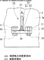
図1、図2において、破砕部12とベルトコンベヤ16との間で、2つの駆動軸3,4間の略中央部の下方に、同軸方向の、破砕部12のほぼ全長にわたって、第1実施形態の破砕物方向変更部材20を設けている。図3は図1のA−A矢視図であり、破砕物方向変更部材20の構成を示す正面断面図である。図1、図3において、ケース2の前記駆動軸3,4端側の内壁面2a,2aの下部には、それぞれ駆動軸3,4方向の左右側方に、メネジ22を有する左右一対のブラケット21,21が固着されている。破砕物方向変更部材20である縦板状部材23は、前記破砕部12の長手方向(即ち、駆動軸3,4方向)長さにほぼ等しい長さの縦板24と、この縦板24の長手方向両端部下面にそれぞれ固着された取付板25,25とを備えている。縦板状部材23は、前記取付板25,25の下方からボルト26を挿入して前記ブラケット21,21のメネジ22に螺合して、着脱自在に締着されている。縦板24の上面部には山形状27が形成されており、下面部には複数個のメネジ28が設けられている。
【0021】
次に、縦板状部材23の作用について説明する。2軸せん断型破砕機1の破砕部12では、せん断型カッタ10により被破砕物が細かく破砕されるようになっているが、前述したように長物破砕物40が破砕されずに破砕部12の隙間から排出されてしまう場合がある。この長物破砕物40は、スペーサ11とせん断型カッタ10との相対位置との関係から、2点鎖線に示すようにやや斜め方向から落下してきて縦板状部材23に当り、これにより方向を変更してその先端部41はベルトコンベヤ16に当る。その後、長物破砕物40は、せん断カッタ10の回転によって長物破砕物40の長手方向に押されるため、途中で曲がりを生じる。このとき、せん断カッタ10で加えられた排出時の長物破砕物40の運動エネルギ(以後、排出エネルギと呼ぶ)は、その先端部41の縦板状部材23への衝突により低減され、落下時に先端部41がベルトコンベヤ16の表面を押す力は小さくなるので、ベルトコンベヤ16を損傷する恐れは少なくなる。
【0022】
本発明の2軸せん断型破砕機1は上記のような構成としたため、ベルトコンベヤ16の損傷は低減され、耐久性を向上できる。本実施形態の場合、縦板24の幅Bが小さいため、長物破砕物40の方向変更角度は小さく、また長物破砕物40が縦板状部材23に当る度合いがある程度小さいことにより、排出エネルギの低減量は少ないため、例えばアルミニウム、プラスチック等の軽量の長物破砕物に対して有効である。また、縦板状部材23の形状が単純なため、長い板状等、シンプルな形状のものを扱う場合には、破砕物が破砕物方向変更部材20に絡みつく恐れは少ない。
【0023】
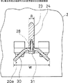
図4は、第2実施形態の破砕物方向変更部材20aを取付けた2軸せん断型破砕機1aの正面断面図であり、図5は破砕物方向変更部材20aの詳細正面断面図である。図4、図5において、軸方向視で裾広がり状の方向変更部材30を、ケース2に取付けられた縦板状部材23の、縦板24の下面部に形成されたメネジ28に、複数個のボルト31で締着する。方向変更部材30の全幅Wは、縦板24の幅Bより広く(例えば5倍以上に)設定している。
【0024】
次に、破砕物方向変後部材20aの作用について説明する。図4において、長物破砕物40は、スペーサ11とせん断型カッタ10との相対位置との関係から、2点鎖線に示すようにやや斜め方向から落下してきて方向変更部材30に当り、これにより方向を変更してその先端部41はベルトコンベヤ16に当る。その後、せん断カッタ10に押されるため、長物破砕物16は途中で曲がりを生じる。その曲がり角度は、裾広がり状の方向変更部材30の全幅Wが縦板24の幅Bよりも広いので、前述の縦板状部材23の時の角度より大きい。そのため、長物破砕物40は折損し、または座屈する場合があるが、その場合にはベルトコンベヤ16に力は殆ど加わらない。また、折損や座屈をしなくても、裾広がり状の方向変更部材30に衝突して大きく方向変更されるため長物破砕物40の排出エネルギは大幅に低減されるので、その先端部41がベルトコンベヤ16の表面を押す力は極端に小さくなり、ベルトコンベヤ16を損傷する恐れは大幅に少なくなる。
【0025】
本実施形態の場合、例えば鉄材やアルミサッシ等の硬質で、比較的剛性の高い長物破砕物に対して有効である。
【0026】
上述のように、本発明の縦板状部材又は裾広がり状の方向変更部材は着脱自在である。そのため、ビニールシート等の絡みやすい被破砕材料が比較的少ない場合には縦板状部材のみとして、軽量の長物破砕物の排出エネルギを低減できる。絡み易い被破砕材料が無いか、又は微小の時は、裾広がり状の方向変更部材を取付けることにより、比較的剛性の高い長物破砕物の排出エネルギをも大幅に低減できる。また、畳やビニールシート等の絡み易い被破砕材料が多い場合には、縦板状部材及び裾広がり状の方向変更部材等の破砕物方向変更部材を取り外して破砕材料の流れを良くすることができる。すなわち、各種の被破砕材料の材質等に対応して、破砕物方向変更部材を容易に選択的に交換でき、最適な状態で作業することができる。これにより、作業効率を向上でき、かつ、ベルトコンベヤの損傷も低減できる。
【0027】
図6は、第3実施形態の破砕物方向変更部材20bを取付けた2軸せん断型破砕機1bの側面断面図である。図6において、破砕物方向変更部材20bは、前記縦板状部材23の縦板24の両側面部に、ベルトコンベヤ16の搬送方向(図の白矢印で示す)に向けて傾斜した複数個の傾斜ガイド部材32を設けて構成している。長物破砕物40は2点鎖線で示すように傾斜ガイド部材32に衝突し、せん断カッタ10の回転力によって途中で曲がり、ベルトコンベヤ16の搬送方向に向けて傾斜する。そのため、長物破砕物40の排出エネルギは低減され、その先端部41が押す力は大幅に減少するので、ベルトコンベヤ16の破損を防止することができる。
【0028】
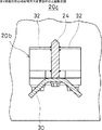
図7は、第4実施形態の破砕物方向変更部材20cの正面断面図である。図7において、前記第3実施形態と同様の破砕物方向変更部材20bの縦板24の下部に、裾広がり状の方向変更部材30を取付けている。これにより、長物破砕物は前記駆動軸3,4方向及びそれに垂直な方向に大きく曲げられるため、排出エネルギは大幅に低減される。したがって、ベルトコンベヤ16の損傷防止に一層の効果を期待できる。
【0029】
なお、以上の実施形態では、搬送手段はベルトコンベヤを例に挙げて説明しているが、これに限定されず、例えば振動フィーダ等の他の搬送手段であってもよい。また、傾斜ガイド部材は縦板状部材に取付けているが、裾広がり状の方向変更部材に取付けてもよい。
【0030】
以上説明したように、本発明によると、2軸せん断型破砕機の破砕部と搬送手段との間に、破砕物方向変更部材を設けたので、長物破砕物がこれに衝突し、また排出方向が変更されて曲げられることにより、長物破砕物の排出エネルギが低減される。このため、搬送手段の損傷を防止でき、耐久性を向上できる。
また、破砕物方向変更部材として、横幅のやや狭い、シンプルな構造の縦板状部材や、これよりも幅広の裾広がり状の方向変更部材、等を選択的に着脱自在に取り付け可能としたので、被破砕物の種類、材質や絡み易さの程度に応じて上記の部材を選択的に取付けることができる。これにより、被破砕物に適した状態(前記排出方向変更部材の無い状態も含む)で破砕できるので、効率的な破砕ができる。
【図面の簡単な説明】
【図1】第1実施形態に係る2軸せん断型破砕機の側面断面図である。
【図2】図1の正面断面図である。
【図3】第1実施形態に係る破砕物方向変更部材の正面断面図である。
【図4】第2実施形態に係る2軸せん断型破砕機の正面断面図である。
【図5】第2実施形態の破砕物方向変更部材の正面断面図である。
【図6】第3実施形態に係る2軸せん断型破砕機の側面断面図である。
【図7】第4実施形態の破砕物方向変更部材の正面断面図である。
【図8】従来の移動式破砕機の側面断面図である。
【図9】従来の2軸せん断型破砕機の平面断面図である。
【図10】図9の正面断面図である。
【符号の説明】
1,1a,1b…2軸せん断型破砕機、2…ケース、2a…内壁面、3,4…駆動軸、10…せん断型カッタ、11…スペーサ、12…破砕部、15…搬送手段、16…ベルトコンベヤ、20,20a,20b,20c…破砕物方向変更部材、21…ブラケット、22,28…メネジ、23…縦板状部材、24…縦板、25…取付板、30…方向変更部材、32…傾斜ガイド部材。[0001]
BACKGROUND OF THE INVENTION
The present invention relates to an apparatus for preventing a crushed material transport device of a biaxial shear type crusher from being damaged by a crushed material.
[0002]
[Prior art]
2. Description of the Related Art Conventionally, in a rotary crusher, a device for preventing scattering around a crushed material and damage due to a crushed material of a crushed material transport device has been devised. For example,
[0003]
FIG. 8 is a side sectional view showing the configuration of the mobile crusher described in
[0004]
[Patent Document 1]
JP-A-9-141123 (page 3-4, FIG. 1)
[0005]
[Problems to be solved by the invention]
However, when the techniques of the impact crusher anti-scattering plate and the belt protection plate as described above are applied to a biaxial shearing type crusher, the following problems occur. In other words, crushed material from the crusher may be mixed with elongated crushed material that has been discharged without being crushed, preventing the conveyor belt conveyor from being damaged by this mixed crushed material. There is a problem that you can not do. Since there is no patent document relating to prevention of damage to the belt conveyor of the biaxial shearing type crusher, the above-mentioned problem of damage to the belt conveyor of the biaxial shearing type crusher will be described below.
[0006]
FIG. 9 is a plan sectional view of a conventional
[0007]
The biaxial
[0008]
The present invention has been made paying attention to the above-described problems, and an object of the present invention is to provide a biaxial shearing type crusher that prevents damage to a conveying means due to a long material crushed material mixed in the crushed material.
[0009]
[Means, actions and effects for solving the problems]
In order to achieve the above object, according to a first aspect of the present invention, in a biaxial shearing type crusher, a case, two drive shafts that are rotatably supported by the case, and two drive shafts arranged in parallel are attached to the drive shaft. A crushing part for crushing the object to be crushed with a shear-type cutter, and a conveying means arranged below the case and conveying the crushed material discharged from the crushing part, between the crushing part and the conveying means A crushing material direction changing member for changing the discharge direction of the crushing material discharged from the crushing part , and the crushing material direction changing member is disposed between the two drive shafts and in the longitudinal direction of the drive shaft. Thus, it is a vertical plate-like member provided over almost the entire length of the crushing part, and the surface facing the crushing part is directed to the same side as the conveying direction of the conveying means on the side surface part of the crushing material direction changing member. It has a structure provided with inclined inclined guide member .
[0010]
According to 1st invention, the discharge direction of the crushing material discharged | emitted from a crushing part is changed by the crushing material direction change member. That is, the discharge direction of long crushed material such as wood, bamboo, aluminum sash, iron, etc. mixed in the crushed material discharged downward from the crushing part is changed to another direction by hitting the crushed material direction changing member. . Therefore, the discharge energy of the crushed long product whose direction has been changed is reduced, and even if the leading end of the crushed long product hits a conveying means such as a belt conveyor, there is little fear of damaging the tip, and durability can be improved. In addition, since the long crushed material discharged from the crushing part is contacted with the vertical plate member that is the crushed material direction changing member and the discharge direction is changed, it prevents damage to the conveying means such as the belt conveyor and is durable. Can be improved. In the case of the present invention, since the width of the vertical plate-like member is relatively small, the direction change angle of the long object is small, and the amount of reduction in the discharge energy is small. For this reason, for example, it is effective for a lightweight crushed object such as aluminum or plastic, and if it has a simple shape such as a long plate shape, the crushed object is less likely to be entangled with the crushed object direction changing member. In addition, the crushed long material discharged from the crushing portion hits the inclined guide member and is changed in direction toward the conveying direction of the conveying means such as a belt conveyor, so that the discharged energy is reduced and the long crushed material is reduced. The force with which the leading end of the sheet comes into contact with the conveying means is reduced, the conveying means can be prevented from being damaged, and the durability can be improved.
[0015]
In a second aspect based on the first aspect , the vertical plate member is detachable.
[0016]
According to the 2nd invention, when there are comparatively few materials to be entangled such as a vinyl sheet, it is possible to change the discharge direction of the light and long crushed material by using only the vertical plate member and reduce the discharge energy. When there is no material to be entangled easily or when it is very small, the direction changing member is widened at the bottom, and the direction changing angle of a relatively high-rigidity long material can be increased to greatly reduce the discharge energy. Moreover, when there are many crushed materials, such as a tatami mat and a vinyl sheet, the flow direction of a crushed material can be improved by removing a skirt-spreading direction changing member and a vertical plate member. That is, it is possible to easily work on various types of materials to be crushed in an optimum state, improve work efficiency, and reduce damage to a conveying means such as a belt conveyor.
[0019]
DETAILED DESCRIPTION OF THE INVENTION
Embodiments of a biaxial shear type crusher according to the present invention will be described in detail below with reference to the drawings.
[0020]
FIG. 1 is a side sectional view of a
1 and 2, between the crushing
[0021]
Next, the operation of the
[0022]
Since the
[0023]
FIG. 4 is a front sectional view of the biaxial
[0024]
Next, the effect | action of the crushed material
[0025]
In the case of this embodiment, for example, it is effective for crushed long objects that are hard and relatively high in rigidity, such as iron materials and aluminum sashes.
[0026]
As described above, the vertical plate-shaped member or the hem-spreading direction changing member of the present invention is detachable. For this reason, when there are relatively few materials to be crushed such as vinyl sheets, it is possible to reduce the discharge energy of a lightweight crushed material only as a vertical plate member. When there is no material to be entangled easily, or when it is very small, it is possible to significantly reduce the discharge energy of a relatively high-rigid crushed material by attaching a direction-changing member that spreads at the bottom. In addition, when there are many materials to be crushed easily such as tatami mats and vinyl sheets, it is possible to improve the flow of the crushed material by removing the crushed material direction changing members such as the vertical plate-shaped member and the hem-spreading direction changing member. it can. In other words, the crushed object direction changing member can be easily and selectively exchanged according to the material of various materials to be crushed, and work can be performed in an optimum state. Thereby, work efficiency can be improved and the damage of a belt conveyor can also be reduced.
[0027]
FIG. 6 is a side sectional view of a biaxial
[0028]
FIG. 7 is a front sectional view of the crushed object
[0029]
In the above embodiment, the conveying means is described by taking a belt conveyor as an example. However, the conveying means is not limited thereto, and may be other conveying means such as a vibration feeder. Moreover, although the inclination guide member is attached to the vertical plate-like member, it may be attached to a direction changing member having a hem shape.
[0030]
As described above, according to the present invention, since the crushed material direction changing member is provided between the crushing part of the biaxial shear type crusher and the conveying means, the long material crushed material collides with this, and the discharge direction Is changed and bent, the discharge energy of the crushed long object is reduced. For this reason, damage to the conveying means can be prevented, and durability can be improved.
In addition, as the crushed material direction changing member, a vertical plate-like member having a slightly narrow width and a simple structure, a direction changing member having a wider hem, and the like can be selectively detachably attached. The above-mentioned members can be selectively attached according to the kind of material to be crushed, the material, and the degree of entanglement. Thereby, since it can crush in the state suitable for a to-be-crushed object (including the state without the said discharge direction changing member), efficient crushing can be performed.
[Brief description of the drawings]
FIG. 1 is a side sectional view of a biaxial shear crusher according to a first embodiment.
FIG. 2 is a front sectional view of FIG.
FIG. 3 is a front sectional view of a crushed object direction changing member according to the first embodiment.
FIG. 4 is a front sectional view of a biaxial shear crusher according to a second embodiment.
FIG. 5 is a front sectional view of a crushed object direction changing member according to a second embodiment.
FIG. 6 is a side sectional view of a biaxial shear crusher according to a third embodiment.
FIG. 7 is a front sectional view of a crushed object direction changing member according to a fourth embodiment.
FIG. 8 is a side sectional view of a conventional mobile crusher.
FIG. 9 is a plan sectional view of a conventional biaxial shear type crusher.
10 is a front sectional view of FIG. 9. FIG.
[Explanation of symbols]
DESCRIPTION OF
Claims (2)
ケース(2) と、
該ケース(2) に回転自在に支持された、並列する2本の駆動軸(3,4)と、
該駆動軸(3,4) に取付けられたせん断型カッタ(10)で被破砕物を破砕する破砕部(12)と、
前記ケース(2) の下方に配置され、前記破砕部(12)から排出される破砕物を搬送する搬送手段(15)とを備え、
前記破砕部(12)と搬送手段(15)との間に、前記破砕部(12)から排出される破砕物の排出方向を変更する破砕物方向変更部材(20)を設け、
前記破砕物方向変更部材 (20) は、前記2本の駆動軸 (3,4) 間の下方で、前記駆動軸 (3,4) の長手方向で、前記破砕部 (12) のほぼ全長にわたって設けられた縦板状部材 (23) であり、
前記破砕物方向変更部材 (20) の側面部に、前記破砕部 (12) と対向した面を前記搬送手段 (15) の搬送方向と同じ側に向けて傾斜した傾斜ガイド部材 (32) を設けた
ことを特徴とする2軸せん断型破砕機。In the biaxial shear type crusher,
Case (2) and
Two drive shafts (3, 4) arranged in parallel and rotatably supported by the case (2);
A crushing section (12) for crushing an object to be crushed with a shear type cutter (10) attached to the drive shaft (3,4);
A conveying means (15) that is disposed below the case (2) and conveys the crushed material discharged from the crushing section (12),
Between the crushing part (12) and the conveying means (15), a crushing material direction changing member ( 20 ) for changing the discharge direction of the crushing material discharged from the crushing part (12) is provided ,
The crushed material direction changing member (20) is below between the two drive shafts (3, 4), in the longitudinal direction of the drive shaft (3,4), substantially the entire length of the crushing part (12) It is a vertical plate member (23) provided,
An inclined guide member (32) is provided on the side surface of the crushed material direction changing member (20) so that the surface facing the crushed portion (12) is inclined toward the same side as the conveying direction of the conveying means (15). A biaxial shearing type crusher characterized by that.
前記縦板状部材 (23)は、着脱自在である
ことを特徴とする2軸せん断型破砕機。In the biaxial shear type crusher according to claim 1 ,
The vertical plate member (23) is detachable, and is a biaxial shearing type crusher.
Priority Applications (1)
| Application Number | Priority Date | Filing Date | Title |
|---|---|---|---|
| JP2002377814A JP4067397B2 (en) | 2002-12-26 | 2002-12-26 | 2-axis shear type crusher |
Applications Claiming Priority (1)
| Application Number | Priority Date | Filing Date | Title |
|---|---|---|---|
| JP2002377814A JP4067397B2 (en) | 2002-12-26 | 2002-12-26 | 2-axis shear type crusher |
Publications (2)
| Publication Number | Publication Date |
|---|---|
| JP2004202455A JP2004202455A (en) | 2004-07-22 |
| JP4067397B2 true JP4067397B2 (en) | 2008-03-26 |
Family
ID=32814872
Family Applications (1)
| Application Number | Title | Priority Date | Filing Date |
|---|---|---|---|
| JP2002377814A Expired - Fee Related JP4067397B2 (en) | 2002-12-26 | 2002-12-26 | 2-axis shear type crusher |
Country Status (1)
| Country | Link |
|---|---|
| JP (1) | JP4067397B2 (en) |
Families Citing this family (3)
| Publication number | Priority date | Publication date | Assignee | Title |
|---|---|---|---|---|
| KR100686637B1 (en) * | 2006-04-28 | 2007-02-26 | 이상호 | Shredding compression structure for document shredder |
| JP4986573B2 (en) * | 2006-10-30 | 2012-07-25 | 日立建機株式会社 | Shear type crusher |
| JP6476532B1 (en) * | 2018-06-12 | 2019-03-06 | 三菱重工環境・化学エンジニアリング株式会社 | Twin screw crusher |
-
2002
- 2002-12-26 JP JP2002377814A patent/JP4067397B2/en not_active Expired - Fee Related
Also Published As
| Publication number | Publication date |
|---|---|
| JP2004202455A (en) | 2004-07-22 |
Similar Documents
| Publication | Publication Date | Title |
|---|---|---|
| US10099224B2 (en) | Material reducing device | |
| JP6671080B2 (en) | Crude crusher for waste plastics | |
| US20090050724A1 (en) | Device for comminuting all types of parts | |
| JP4067397B2 (en) | 2-axis shear type crusher | |
| JP4453102B2 (en) | Crushing machine | |
| CA2458874C (en) | Bale processor with pre-disintegrator | |
| JP3246504U (en) | Wood grinding equipment | |
| JP2010000431A (en) | Unpacking machine | |
| JP3894744B2 (en) | Bulk material crusher | |
| EP2976157B1 (en) | Material reducing device | |
| JP4261434B2 (en) | Crusher | |
| JP4411009B2 (en) | Crusher | |
| CN209283780U (en) | A dual-channel straw crushing mechanism | |
| JP2003205250A (en) | Bits for tab crusher, tab crusher, self-propelled tub crusher, and usage of tab crusher | |
| JP2001334161A (en) | Crushing machine | |
| TWI555579B (en) | Conveying crushing device | |
| JP2759625B2 (en) | Cutting machine | |
| JP2004345765A (en) | Self-traveling recycle machine and conveyor device used therefor | |
| JP2006034245A (en) | Threshing device | |
| JPH11128762A (en) | Coarse material crushing device | |
| JP2891398B2 (en) | Wood crusher | |
| JP2012081368A (en) | Crusher | |
| KR102467668B1 (en) | Envelope shredding apparatus | |
| JPH1043621A (en) | Apparatus for crushing treatment of foamed styrol material and the like | |
| JP3661188B2 (en) | Biaxial shearing crusher |
Legal Events
| Date | Code | Title | Description |
|---|---|---|---|
| A621 | Written request for application examination |
Free format text: JAPANESE INTERMEDIATE CODE: A621 Effective date: 20051114 |
|
| A977 | Report on retrieval |
Free format text: JAPANESE INTERMEDIATE CODE: A971007 Effective date: 20070824 |
|
| A131 | Notification of reasons for refusal |
Free format text: JAPANESE INTERMEDIATE CODE: A131 Effective date: 20071003 |
|
| A521 | Written amendment |
Free format text: JAPANESE INTERMEDIATE CODE: A523 Effective date: 20071120 |
|
| TRDD | Decision of grant or rejection written | ||
| A01 | Written decision to grant a patent or to grant a registration (utility model) |
Free format text: JAPANESE INTERMEDIATE CODE: A01 Effective date: 20080108 |
|
| A61 | First payment of annual fees (during grant procedure) |
Free format text: JAPANESE INTERMEDIATE CODE: A61 Effective date: 20080108 |
|
| FPAY | Renewal fee payment (event date is renewal date of database) |
Free format text: PAYMENT UNTIL: 20110118 Year of fee payment: 3 |
|
| R150 | Certificate of patent or registration of utility model |
Free format text: JAPANESE INTERMEDIATE CODE: R150 Ref document number: 4067397 Country of ref document: JP Free format text: JAPANESE INTERMEDIATE CODE: R150 |
|
| FPAY | Renewal fee payment (event date is renewal date of database) |
Free format text: PAYMENT UNTIL: 20110118 Year of fee payment: 3 |
|
| FPAY | Renewal fee payment (event date is renewal date of database) |
Free format text: PAYMENT UNTIL: 20120118 Year of fee payment: 4 |
|
| FPAY | Renewal fee payment (event date is renewal date of database) |
Free format text: PAYMENT UNTIL: 20130118 Year of fee payment: 5 |
|
| FPAY | Renewal fee payment (event date is renewal date of database) |
Free format text: PAYMENT UNTIL: 20130118 Year of fee payment: 5 |
|
| FPAY | Renewal fee payment (event date is renewal date of database) |
Free format text: PAYMENT UNTIL: 20140118 Year of fee payment: 6 |
|
| LAPS | Cancellation because of no payment of annual fees |