JP4077458B2 - Stair scaffolding equipment - Google Patents
Stair scaffolding equipment Download PDFInfo
- Publication number
- JP4077458B2 JP4077458B2 JP2005045619A JP2005045619A JP4077458B2 JP 4077458 B2 JP4077458 B2 JP 4077458B2 JP 2005045619 A JP2005045619 A JP 2005045619A JP 2005045619 A JP2005045619 A JP 2005045619A JP 4077458 B2 JP4077458 B2 JP 4077458B2
- Authority
- JP
- Japan
- Prior art keywords
- scaffolding
- ladder
- staircase
- plate
- landing
- Prior art date
- Legal status (The legal status is an assumption and is not a legal conclusion. Google has not performed a legal analysis and makes no representation as to the accuracy of the status listed.)
- Expired - Fee Related
Links
Images
Landscapes
- Movable Scaffolding (AREA)
Description
本発明は、建物の階段吹抜き内で階段壁面等を補修したり、照明器具の取り替え作業等な行うような場合に使用される階段用足場装置に関するもので、特に下階から踊り場までの下階側階段部と踊り場から上階までの上階側階段部とが折り返し状になっている折り返し階段用の足場装置に関する。 The present invention relates to a stairway scaffold device used for repairing a staircase wall in a stairwell of a building or replacing a lighting fixture. The present invention relates to a scaffolding device for a folded staircase in which a floor side staircase portion and an upper floor side staircase portion from a landing to an upper floor are folded.
上記のような折り返し階段内で壁面補修等の作業を行う場合、従来では、梯子を踊り場や階段部から階段吹抜き内の壁面に立て掛け、この梯子に乗って作業を行っていたが、梯子による作業では作業範囲が狭いため、梯子を度々移動させる必要がある上に、梯子を階段部のステップに設置させる場合は非常に不安定で危険であるため、複数人の作業員で梯子を保持しておく必要があり、従って作業能率が非常に悪かった。 In the past, when performing work such as wall repair in the folded stairs as described above, a ladder was leaned against the wall in the stairwell from the landing or staircase, and the work was carried on this ladder. Since the work range is narrow in work, it is necessary to move the ladder frequently, and it is very unstable and dangerous when installing the ladder on the steps of the staircase, so multiple workers hold the ladder. Therefore, the work efficiency was very bad.
本発明は、上記の課題に鑑み、折り返し階段の吹抜き内での各種作業を安全にして且つ能率良く行えるようにした階段用足場装置を提供することを目的とする。 In view of the above-described problems, an object of the present invention is to provide a stairway scaffold device that can safely and efficiently perform various operations within a blowout of a folded staircase.
上記課題を解決するための手段を、後述する実施形態の参照符号を付して説明すると、請求項1に係る発明は、下階2から踊り場1までの下階側階段部3と踊り場1から上階4までの上階側階段部5とが折り返し状になっている折り返し階段に使用される階段用足場装置であって、図5の(b) にBで示すように、
上階4の階段吹抜き口So側に設けられた手摺り7に掛止固定される足場固定枠8と、 足場固定枠8に端部を支持される伸縮式足場板9と、の組み合わせからなり、
足場固定枠8は、一対の縦枠11、11間に足場支持杆12を上下複数段に横架してなる梯子状本体13の上部に、前記手摺り7の上端部に掛嵌するコ字枠状の掛嵌部14を連設することによって形成されるもので、階段吹抜き口Soに臨んで対向する両側の手摺り7a,7bに夫々足場固定枠8,8を掛止固定し、両足場固定枠8,8の梯子状本体13,13の足場支持杆12,12に伸縮式足場板9の両端部を支持させるようにしたことを特徴とする。
Means for solving the above problems will be described with reference numerals of the embodiments described later. The invention according to
From a combination of a scaffolding fixed
The
請求項2に係る発明は、下階2から踊り場1までの下階側階段部3と踊り場1から上階4までの上階側階段部5とが折り返し状になっている折り返し階段に使用される階段用足場装置であって、図2及び図6にA1,A2で示すように、
上階4の階段吹抜き口So側に設けられた手摺り7に掛止固定される足場固定枠8と、 足場固定枠8に端部を支持される伸縮式足場板9と、
夫々一対の脚柱23,23間に踏桟24を横架してなる両側一対の梯子状脚体22,22の上端部どうしを枢着して形成された伸縮脚26付き脚立10と、の組み合わせからなり、
足場固定枠8は、一対の縦枠11,11間に足場支持杆12を上下複数段に横架してなる梯子状本体13の上部に、前記手摺り7の上端部に掛嵌するコ字枠状の掛嵌部14を連設することによって形成されるもので、この足場固定枠8を前記手摺り7に掛止固定して、梯子状本体13の足場支持杆12に前記足場板9の一端部を支持させるようにし、脚立10は、踊り場1もしくは上階4の何れかに設置されるか、又は踊り場1、上階4、階段部3,5の何れかに跨がって設置され、両梯子状脚体22,22に前記足場板9の他端側を貫通させて両梯子状脚体22,22の踏桟24,24に支持させるようにしたことを特徴とする。
The invention according to claim 2 is used for a folded staircase in which a lower floor
A scaffolding fixed
A
The
上記解決手段による発明の効果を、後述する実施形態の参照符号を付して説明すると、請求項1に係る発明によれば、階段吹抜き口Soに臨んで対向する両側の手摺り7a,7bに夫々足場固定枠8,8を掛止固定し、両足場固定枠8,8の梯子状本体13,13の足場支持杆12,12に伸縮式足場板9の両端部を支持させるようにしたものであるから、足場板9は水平姿勢で支持固定されることになり、従って作業者は、この足場板9の上に乗って適宜に移動しながら、階段吹抜きS内での補修作業や、照明器具の取り替え作業等を安全且つ能率良く行うことができる。
The effect of the invention by the above solution will be described with reference numerals of the embodiments described later. According to the invention of
請求項2に係る発明によれば、伸縮式足場板9の一端部を、上階4の手摺り7に掛止固定した足場固定枠8の足場支持杆12に支持させ、この足場板9の他端側を、踊り場1もしくは上階4の何れかに設置するか、又は踊り場1、上階4、階段部3,5の何れかに跨がって設置した脚立10の両梯子状脚体22,22の所要の踏桟24,24に支持させるようにしたものであるから、足場板9は水平姿勢で支持固定されることになり、従って作業者は、この足場板9の上に乗って適宜に移動しながら、階段吹抜きS内での階段壁面等の補修作業、照明器具の取り替え作業等を能率良く安全に行うことができる。
According to the invention of claim 2, one end portion of the
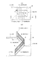
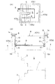
以下に本発明の好適な実施形態を図面に基づいて説明すると、図1の(a) は折り返し階段を示す平面図、(b) は(a) のX−X線断面図であり、この図において、1は階段の踊り場で、下階2から踊り場1までの下階側階段部3と、踊り場1から上階4までの上階側階段部5とが図1の(a) に示すように折り返し状になっており、これらの踊り場1及び階段部3,5を含む垂直な空間部が階段吹抜きSを形成している。また、下階側階段部3及び上階側階段部5の内側縁に沿って傾斜状の階段手摺り6が設置され、これらの階段部3,5及び踊り場1の外側面は壁Wを形成し、そして上階4の階段吹抜き口Soには下階側階段部3の下段部上方位置に水平状の吹抜き口手摺り7が設置されている。
A preferred embodiment of the present invention will be described below with reference to the drawings. FIG. 1 (a) is a plan view showing a folded staircase, and FIG. 1 (b) is a sectional view taken along line XX of FIG. 1 is a landing for stairs, and the
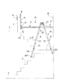
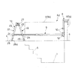
図2は、図1の(a) ,(b) で示されるような折り返し階段に使用される階段用足場装置A1を示す側面図である。この階段用足場装置A1は、吹抜き口手摺り7に掛止固定される足場固定枠8と、この足場固定枠8に端部を支持される伸縮式足場板9と、両側一対の梯子状脚体22,22の上端部どうしを枢着して形成された伸縮脚26付き脚立10と、の組合せからなる。
FIG. 2 is a side view showing a stairway scaffolding device A1 used for a folding staircase as shown in FIGS. 1 (a) and 1 (b). This stairway scaffolding device A1 includes a
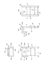
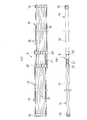
足場固定枠8は、図7の(a) 〜(d) から分かるように、一対の縦枠11,11間に足場支持杆12を上下複数段に横架してなる梯子状本体13の上部に、前記吹抜き口手摺り7の上端部に掛嵌されるコ字枠状の掛嵌部14を連設することにより形成され、掛嵌部14は、梯子状本体13の両縦枠14,14の上端部に夫々直角に連結された水平杆14a,14aと、両水平杆14a,14aの先端部に垂下連結された垂下片14b,14bと、両垂下片14b,14bの下端部をつなぐ連結片14cとからなり、両水平杆14a,14aの基端部どうしは補強杆14dによって連結されている。尚、梯子状本体13の縦枠11と掛嵌部14の垂下片14bとの間隔は、吹抜き口手摺り7の厚さより僅かに広くなるように設定される。
As can be seen from FIGS. 7A to 7D, the
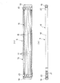
伸縮式足場板9は、図8の(a) ,(b) 及び図9の(a) ,(b) に示すように足場板長さ方向に相対移動自在に連結された一対の足場板本体15,16からなる周知構造のもので、各足場板本体15,16は、足場板幅方向に間隔をおいて配置されたアルミ押出形材製の足場板部材17,18を備え、一方の足場板本体15の足場板部材17が他方の足場板本体16の足場板部材18間に足場板長さ方向スライド自在に介在されている。一方の足場板本体15の足場板部材17の足場板長さ方向一端側及び他方の足場板本体16の足場板部材18の足場板長さ方向他端側は、夫々連結部材19,19によって相互に連結され、また一方の足場板本体15の足場板部材17の足場板長さ方向他端側及び他方の足場板本体16の足場板部材18の足場板長さ方向一端側は、夫々全足場板部材17,18に亘って外嵌されて足場板長さ方向にスライド自在に支持されたバンドプレート20により相互に連結されている。
As shown in FIGS. 8 (a) and 8 (b) and FIGS. 9 (a) and 9 (b), the
従って、両足場板本体15,16は、足場板長さ方向に相対移動自在とされ、それにより足場板9は長さ方向に伸縮自在に構成されている。また、一方の足場板本体15における足場板幅方向一端側の足場板部材17と、この足場板部材17に対向する、他方の足場板本体16の足場板幅方向一端側の足場板部材18との間には、両方の足場板本体15,16を所要の伸縮位置にロックするロック装置21が介設されている。図8の(a) は収縮状態での足場板9の平面図、(b) はその正面図であり、図9の(a) は伸張状態での足場板9の平面図、(b) はその正面図である。
Accordingly, the two
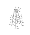
脚立10は、図10に例示するように、一対の梯子状脚体22,22の上端部どうしを回転連結金具25,25で枢着してなる周知構造のもので、各梯子状脚体22は、両側一対の脚柱23,23と、両脚柱23,23間に上下複数段に横架される踏桟24とによって形成されると共に、各脚柱23には、下端に脚端具26aを備えた伸縮脚26が伸縮可能に連結されている。図示は省略するが、各脚柱23には、伸縮脚26を脚柱23に対して適宜に伸縮調整した位置でロックするロック手段が設けてある。尚、図10において、27は両梯子状脚体22,22を開脚状態に固定するラッチ式のストッパーを示す。
As illustrated in FIG. 10, the
上記のような構成の階段用足場装置A1を、図1の(a) ,(b) で示されるような階段に設置するには、先ず、図2及び図3に示すように、上階4の吹抜き口手摺り7に足場固定枠8を掛止固定し、踊り場1と下階側階段部3とに亘って脚立10を設置する。そして収縮状態とした伸縮式足場板9を所要高さ位置で脚立10の両梯子状脚体22,22に水平方向に貫通させて、この足場板9の一端部を足場固定枠8における梯子状本体13の所要の足場支持杆12に支持させると共に、足場板9の他端側を両梯子状脚体22,22の所要の踏桟24,24に支持させた状態で、足場板9を適宜伸張させて、この足場板9の他端部を踊り場1の壁Wに当接させ、しかして足場板9の両端部を吹抜き口手摺り7と踊り場1の壁Wとに強く押し付けた状態で、足場板本体15,16を所要の伸張位置にロックする。
In order to install the stairway scaffold apparatus A1 having the above-described configuration on the staircase as shown in FIGS. 1A and 1B, first, as shown in FIG. 2 and FIG. The
こうして足場固定枠8と伸縮式足場板9と脚立10との組み合わせからなる階段用足場装置A1を仮設する。この階段用足場装置A1は、伸縮式足場板9の一端部を、上階4の吹抜き口手摺り7に掛止固定した足場固定枠8の足場支持杆12に支持させ、この足場板9の他端側を、踊り場1と下階側階段部3とに亘って脚立10を設置した脚立10の両梯子状脚体22,22の所要の踏桟24,24に支持させると共に、この伸縮式足場板9の両端部を吹抜き口手摺り7と踊り場1の壁Wに強く押し付けているため、足場板9はガタつくことなく水平に安定状態に支持固定され、従って作業者は、この足場板9の上に乗って適宜に移動しながら、階段吹抜きS内での階段壁面等の補修作業や、照明器具の取り替え作業等を能率良くしかも安全に行うことができる。
In this way, a stairway scaffolding device A1 composed of a combination of the
この図2及び図3に示す設置例では、図3及び図4から分かるように、大小2つの脚立10と伸縮式足場板9とからなる他の階段用足場装置Cが、上記階段用足場装置A1と並列状態に設置されている。階段用足場装置Cは、図4に示すように、上階側階段部5を上がり終えた上階4の入口側に丈の低い脚立10(特に10bで示す)を設置すると共に、丈の高い脚立10(特に10aで示す)を上階側階段部5の下段部と踊り場1とに亘って設置し、これら両脚立10a,10bに伸縮式足場板9を貫通させて、足場板9の一端側を脚立10bの両梯子状脚体22,22の所要の踏桟24,24に支持させ、足場板9の他端側を脚立10aの両梯子状脚体22,22の所要の踏桟24,24に支持させ、その他端部を踊り場1の壁Wに当接させている。
In the installation example shown in FIG. 2 and FIG. 3, as can be seen from FIG. 3 and FIG. 4, the other stairway scaffolding device C composed of the two large and
また図3に示すように、階段用足場装置Cの伸縮式足場板9と階段用足場装置A1の伸縮式足場板9とに亘って他の伸縮式足場板9を掛け渡して、両方の足場装置A1,Cを互いに行き来できるようにしている。上記他の伸縮式足場板9はその両端部を踊り場1の対向する壁W,Wに押し付けた状態としている。
Further, as shown in FIG. 3, the other
尚、階段用足場装置A1を示す図2の設置例では、脚立10の一方の梯子状脚体22を踊り場1に支持させ、他方の梯子状脚体22を下階側階段部3の上段部で支持させているが、脚立10の両梯子状脚体22,22を共に踊り場1上で支持させるようにしてもよい。
In the installation example of FIG. 2 showing the stair scaffolding device A1, one ladder-
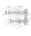
図5は、図1と同様な折り返し階段を示したものであるが、図1の階段では、吹抜き口手摺り7が上階4の、下階側階段部3の下段部上方位置にのみ設けられているのに対し、この図5の場合は、吹抜き口手摺り7が、上階側階段部5を上がり終えて上階4に入る入口部を除いて上階4の階段吹抜き口Soを囲むように設けられている場合で、(a) はこのような折り返し階段を吹抜き口手摺り7のところで水平に断面した平面断面図である。
FIG. 5 shows a folded staircase similar to FIG. 1, but in the staircase of FIG. 1, the
図5の(b) は、図5の(a) で示される折り返し階段に使用される階段用足場装置Bを示す側面図である。この階段用足場装置Bは、上階側階段部5を上がり終えた上階入口部を除いて上階4の階段吹抜き口Soを囲むように設けられた吹抜き口手摺り7に掛止固定される足場固定枠8と、この足場固定枠8に端部を支持される伸縮式足場板9との組み合わせからなるもので、階段吹抜き口Soに臨んで対向する両側の吹抜き口手摺り7a,7bに夫々足場固定枠8,8を掛止固定し、これら両足場固定枠8,8の梯子状本体13,13の足場支持杆12,12に伸縮式足場板9の両端部を支持させるようにしたものである。
FIG. 5B is a side view showing the stairway scaffold device B used for the folded staircase shown in FIG. This stairway scaffolding device B is latched on the
この階段用足場装置Bの設置にあたっては、先ず、階段吹抜き口Soに臨んで対向する両側の吹抜き口手摺り7,7に足場固定枠8,8を夫々掛止固定し、そして収縮状態とした伸縮式足場板9を水平姿勢で両足場固定枠8,8の梯子状本体13,13間に挿入し、その後、この足場板9を伸張させながら、足場板9の両端部を両足場固定枠8,8の梯子状本体13,13の夫々所要の足場支持杆12,12に夫々支持させると共に、足場板9を伸張させて、その両端部を、対向する両側の吹抜き口手摺り7,7に押し付けた状態で、足場板9の足場板本体15,16を所要の伸張位置にロックする。
In installing the stair scaffolding device B, first, the
こうして両側一対の足場固定枠8,8と伸縮式足場板9との組み合わせからなる階段用足場装置Bを仮設する。この階段用足場装置Bは、階段吹抜き口Soに臨んで対向する両側の吹抜き口手摺り7a,7bに夫々足場固定枠8,8を掛止固定し、これら両足場固定枠8,8の梯子状本体13,13の足場支持杆12,12に伸縮式足場板9の両端部を支持させると共に、伸縮式足場板9の両端部を、対向する両側の吹抜き口手摺り7,7に押し付けた状態としているから、足場板9はガタつくことなく水平姿勢で安定状態に支持固定されることになり、従って作業者は、この足場板9の上に乗って適宜に移動しながら、階段吹抜きS内での補修作業や、照明器具の取り替え作業等をより安全にして且つ能率良く行うことができる。
In this way, a stairway scaffolding device B composed of a combination of a pair of
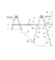
図6は、図5の(a) で示される折り返し階段に使用される階段用足場装置A2を示す側面図である。この階段用足場装置A2は、図2によって説明した階段用足場装置A1と同じ構成であって、図5の(a) から分かるように踊り場1側に位置する吹抜き口手摺り7bに掛止固定される足場固定枠8と、この足場固定枠8に端部を支持される伸縮式足場板9と、両側一対の梯子状脚体22,22の上端部どうしを枢着して形成された伸縮脚26付き脚立10との組合せからなる。この階段用足場装置A2の設置方法は、階段用足場装置A1と同様である。この図6の例では、脚立10の両梯子状脚体22,22を共に上階4で支持させているが、この脚立10の一方の梯子状脚体22を上階4で支持させ、他方の梯子状脚体22を上階側階段部5の上段部で支持させるようにしてもよい。尚、この階段用足場装置A2に使用する脚立10は、比較的丈の低い小形のものでよい。
FIG. 6 is a side view showing the stairway scaffold device A2 used for the folded staircase shown in FIG. This stairway scaffolding device A2 has the same configuration as the stairway scaffolding device A1 described with reference to FIG. 2, and is latched on the
A1 階段用足場装置
A2 階段用足場装置
B 階段用足場装置
C 階段用足場装置
1 踊り場
S 階段吹抜き
So 階段吹抜き口
2 下階
3 下階側階段部
4 上階
5 上階側階段部
6 階段手摺り
7 吹抜き口手摺り
8 足場固定枠
9 伸縮式足場板
10 脚立
11 縦枠
12 足場支持杆
13 梯子状本体
14 コ字枠状掛嵌部
22 梯子状脚体
23 脚柱
24 踏桟
26 伸縮脚
A1 Scaffolding device for stairs A2 Scaffolding device for stairs B Scaffolding device for stairs C Scaffolding device for
Claims (2)
上階の階段吹抜き口側に設けられた手摺りに掛止固定される足場固定枠と、
足場固定枠に端部を支持される伸縮式足場板と、の組み合わせからなり、
足場固定枠は、一対の縦枠間に足場支持杆を上下複数段に横架してなる梯子状本体の上部に、前記手摺りの上端部に掛嵌するコ字枠状の掛嵌部を連設することによって形成されるもので、階段吹抜き口に臨んで対向する両側の手摺りに夫々足場固定枠を掛止固定し、両足場固定枠の梯子状本体の足場支持杆に伸縮式足場板の両端部を支持させるようにした階段用足場装置。 A stair scaffolding device used for a folding staircase in which a lower staircase from a lower floor to a landing and an upper staircase from a landing to an upper floor are folded,
A scaffolding fixed frame that is secured to a handrail provided on the stairs vent opening side of the upper floor;
It consists of a combination with an extendable scaffolding plate whose end is supported by a scaffolding fixing frame,
The scaffolding fixed frame has a U-shaped frame-like hooking part that is hooked on the upper end of the handrail on the upper part of the ladder-like main body in which a scaffolding support rod is horizontally extended in a plurality of stages between a pair of vertical frames. It is formed by connecting the scaffolding fixed frames to the railings on both sides facing the stairwell and facing the ladder support body of the ladder-like body of both scaffolding fixed frames. A stairway scaffolding device that supports both ends of the scaffolding plate.
上階の階段吹抜き口側に設けられた手摺りに掛止固定される足場固定枠と、
足場固定枠に端部を支持される伸縮式足場板と、
夫々一対の脚柱間に踏桟を横架してなる両側一対の梯子状脚体の上端部どうしを枢着して形成された伸縮脚付き脚立と、の組み合わせからなり、
足場固定枠は、一対の縦枠間に足場支持杆を上下複数段に横架してなる梯子状本体の上部に、前記手摺りの上端部に掛嵌するコ字枠状の掛嵌部を連設することによって形成されるもので、この足場固定枠を前記手摺りに掛止固定して、梯子状本体の足場支持杆に前記足場板の一端部を支持させるようにし、脚立は、踊り場もしくは上階の何れかに設置されるか、又は踊り場、上階、階段部の何れかに跨がって設置され、両梯子状脚体に前記足場板の他端側を貫通させて両梯子状脚体の踏桟に支持させるようにした階段用足場装置。
A stair scaffolding device used for a folding staircase in which a lower staircase from a lower floor to a landing and an upper staircase from a landing to an upper floor are folded,
A scaffolding fixed frame that is secured to a handrail provided on the stairs vent opening side of the upper floor;
An extendable scaffolding plate supported at the end by a scaffolding fixing frame;
It consists of a combination of a stepladder with telescoping legs formed by pivotally attaching the upper ends of a pair of ladder-like legs on both sides, each of which is formed by laterally straddling a pair of pedestals,
The scaffolding fixed frame has a U-shaped frame-like hooking part that is hooked on the upper end of the handrail on the upper part of the ladder-like main body in which a scaffolding support rod is horizontally extended in a plurality of stages between a pair of vertical frames. It is formed by connecting the scaffolding fixed frame to the handrail so that one end of the scaffolding plate is supported by the scaffolding support rod of the ladder-shaped main body. Or it is installed on any of the upper floors, or it is installed across any of the landings, upper floors, and staircases, and both ladders are passed through the other end side of the scaffolding plate. A stairway scaffolding device that is supported by a stepped pedestal.
Priority Applications (1)
| Application Number | Priority Date | Filing Date | Title |
|---|---|---|---|
| JP2005045619A JP4077458B2 (en) | 2005-02-22 | 2005-02-22 | Stair scaffolding equipment |
Applications Claiming Priority (1)
| Application Number | Priority Date | Filing Date | Title |
|---|---|---|---|
| JP2005045619A JP4077458B2 (en) | 2005-02-22 | 2005-02-22 | Stair scaffolding equipment |
Publications (2)
| Publication Number | Publication Date |
|---|---|
| JP2006233435A JP2006233435A (en) | 2006-09-07 |
| JP4077458B2 true JP4077458B2 (en) | 2008-04-16 |
Family
ID=37041402
Family Applications (1)
| Application Number | Title | Priority Date | Filing Date |
|---|---|---|---|
| JP2005045619A Expired - Fee Related JP4077458B2 (en) | 2005-02-22 | 2005-02-22 | Stair scaffolding equipment |
Country Status (1)
| Country | Link |
|---|---|
| JP (1) | JP4077458B2 (en) |
-
2005
- 2005-02-22 JP JP2005045619A patent/JP4077458B2/en not_active Expired - Fee Related
Also Published As
| Publication number | Publication date |
|---|---|
| JP2006233435A (en) | 2006-09-07 |
Similar Documents
| Publication | Publication Date | Title |
|---|---|---|
| KR20090028716A (en) | Stairs for use on the construction site | |
| CN112513391A (en) | Retractable stair system and application thereof | |
| AU2019232888A1 (en) | A void platform and a method for providing a platform support across a building void | |
| US6932194B1 (en) | Safety rail for scaffolding | |
| US20170211283A1 (en) | Trestle ladder systems and method | |
| US3307653A (en) | Demountable stairway unit | |
| JP5837332B2 (en) | Working staircase for stairs | |
| JP2016204983A (en) | Staircase temporary scaffolding | |
| JP4077458B2 (en) | Stair scaffolding equipment | |
| KR20100055605A (en) | Improved model assembly stairway | |
| EP1365087B1 (en) | Safety barrier apparatus | |
| KR101621868B1 (en) | A working desk for building | |
| KR200378403Y1 (en) | Working tower for a high place | |
| JP7162111B2 (en) | Structural support for stairs and fixing structure between support for stairs and handrail for stairs | |
| KR101672410B1 (en) | Handrail safety device and stair type movable platform | |
| JP4037964B2 (en) | Assembly type scaffolding | |
| FI128834B (en) | Wall bracket and working platform | |
| KR20090064518A (en) | Safety stairs | |
| JPH0620779U (en) | Sliding stairs | |
| JP4986419B2 (en) | Temporary staircase | |
| JP7514574B1 (en) | Work gondola device and temporary gondola fixing device | |
| KR20150113614A (en) | Safety railing bar | |
| KR102229641B1 (en) | Worktable for engineering work of elevator | |
| JP3982807B2 (en) | Staircase | |
| JP3188928U (en) | Ladder equipment for veranda installation |
Legal Events
| Date | Code | Title | Description |
|---|---|---|---|
| A621 | Written request for application examination |
Free format text: JAPANESE INTERMEDIATE CODE: A621 Effective date: 20060926 |
|
| A977 | Report on retrieval |
Free format text: JAPANESE INTERMEDIATE CODE: A971007 Effective date: 20071225 |
|
| TRDD | Decision of grant or rejection written | ||
| A01 | Written decision to grant a patent or to grant a registration (utility model) |
Free format text: JAPANESE INTERMEDIATE CODE: A01 Effective date: 20080109 |
|
| A61 | First payment of annual fees (during grant procedure) |
Free format text: JAPANESE INTERMEDIATE CODE: A61 Effective date: 20080131 |
|
| R150 | Certificate of patent or registration of utility model |
Ref document number: 4077458 Country of ref document: JP Free format text: JAPANESE INTERMEDIATE CODE: R150 Free format text: JAPANESE INTERMEDIATE CODE: R150 |
|
| FPAY | Renewal fee payment (event date is renewal date of database) |
Free format text: PAYMENT UNTIL: 20110208 Year of fee payment: 3 |
|
| FPAY | Renewal fee payment (event date is renewal date of database) |
Free format text: PAYMENT UNTIL: 20120208 Year of fee payment: 4 |
|
| R250 | Receipt of annual fees |
Free format text: JAPANESE INTERMEDIATE CODE: R250 |
|
| FPAY | Renewal fee payment (event date is renewal date of database) |
Free format text: PAYMENT UNTIL: 20120208 Year of fee payment: 4 |
|
| FPAY | Renewal fee payment (event date is renewal date of database) |
Free format text: PAYMENT UNTIL: 20130208 Year of fee payment: 5 |
|
| R250 | Receipt of annual fees |
Free format text: JAPANESE INTERMEDIATE CODE: R250 |
|
| FPAY | Renewal fee payment (event date is renewal date of database) |
Free format text: PAYMENT UNTIL: 20130208 Year of fee payment: 5 |
|
| FPAY | Renewal fee payment (event date is renewal date of database) |
Free format text: PAYMENT UNTIL: 20140208 Year of fee payment: 6 |
|
| R250 | Receipt of annual fees |
Free format text: JAPANESE INTERMEDIATE CODE: R250 |
|
| R250 | Receipt of annual fees |
Free format text: JAPANESE INTERMEDIATE CODE: R250 |
|
| R250 | Receipt of annual fees |
Free format text: JAPANESE INTERMEDIATE CODE: R250 |
|
| R250 | Receipt of annual fees |
Free format text: JAPANESE INTERMEDIATE CODE: R250 |
|
| R250 | Receipt of annual fees |
Free format text: JAPANESE INTERMEDIATE CODE: R250 |
|
| R250 | Receipt of annual fees |
Free format text: JAPANESE INTERMEDIATE CODE: R250 |
|
| R250 | Receipt of annual fees |
Free format text: JAPANESE INTERMEDIATE CODE: R250 |
|
| R250 | Receipt of annual fees |
Free format text: JAPANESE INTERMEDIATE CODE: R250 |
|
| R250 | Receipt of annual fees |
Free format text: JAPANESE INTERMEDIATE CODE: R250 |
|
| R250 | Receipt of annual fees |
Free format text: JAPANESE INTERMEDIATE CODE: R250 |
|
| R250 | Receipt of annual fees |
Free format text: JAPANESE INTERMEDIATE CODE: R250 |
|
| LAPS | Cancellation because of no payment of annual fees |