JP4090426B2 - Cogeneration equipment - Google Patents
Cogeneration equipment Download PDFInfo
- Publication number
- JP4090426B2 JP4090426B2 JP2003394378A JP2003394378A JP4090426B2 JP 4090426 B2 JP4090426 B2 JP 4090426B2 JP 2003394378 A JP2003394378 A JP 2003394378A JP 2003394378 A JP2003394378 A JP 2003394378A JP 4090426 B2 JP4090426 B2 JP 4090426B2
- Authority
- JP
- Japan
- Prior art keywords
- heater
- cooling water
- flange
- mounting bracket
- electric heater
- Prior art date
- Legal status (The legal status is an assumption and is not a legal conclusion. Google has not performed a legal analysis and makes no representation as to the accuracy of the status listed.)
- Expired - Fee Related
Links
- 239000000498 cooling water Substances 0.000 claims description 43
- 238000003780 insertion Methods 0.000 claims description 19
- 230000037431 insertion Effects 0.000 claims description 19
- 238000002485 combustion reaction Methods 0.000 claims description 12
- 238000011084 recovery Methods 0.000 claims description 11
- 239000007789 gas Substances 0.000 description 23
- XLYOFNOQVPJJNP-UHFFFAOYSA-N water Substances O XLYOFNOQVPJJNP-UHFFFAOYSA-N 0.000 description 23
- 239000000463 material Substances 0.000 description 21
- 229910000831 Steel Inorganic materials 0.000 description 15
- 239000010959 steel Substances 0.000 description 15
- 238000012423 maintenance Methods 0.000 description 7
- 238000007689 inspection Methods 0.000 description 5
- 238000005452 bending Methods 0.000 description 4
- LYCAIKOWRPUZTN-UHFFFAOYSA-N Ethylene glycol Chemical compound OCCO LYCAIKOWRPUZTN-UHFFFAOYSA-N 0.000 description 3
- DNIAPMSPPWPWGF-UHFFFAOYSA-N Propylene glycol Chemical compound CC(O)CO DNIAPMSPPWPWGF-UHFFFAOYSA-N 0.000 description 3
- 239000007864 aqueous solution Substances 0.000 description 2
- 238000010586 diagram Methods 0.000 description 2
- 239000000446 fuel Substances 0.000 description 2
- RYGMFSIKBFXOCR-UHFFFAOYSA-N Copper Chemical compound [Cu] RYGMFSIKBFXOCR-UHFFFAOYSA-N 0.000 description 1
- 229910000881 Cu alloy Inorganic materials 0.000 description 1
- 238000007796 conventional method Methods 0.000 description 1
- 238000001816 cooling Methods 0.000 description 1
- 229910052802 copper Inorganic materials 0.000 description 1
- 239000010949 copper Substances 0.000 description 1
- 238000013461 design Methods 0.000 description 1
- 238000009429 electrical wiring Methods 0.000 description 1
- 230000005611 electricity Effects 0.000 description 1
- 239000002737 fuel gas Substances 0.000 description 1
- 230000017525 heat dissipation Effects 0.000 description 1
- 238000000034 method Methods 0.000 description 1
- 238000012856 packing Methods 0.000 description 1
- 230000000149 penetrating effect Effects 0.000 description 1
- 238000003825 pressing Methods 0.000 description 1
- 239000002918 waste heat Substances 0.000 description 1
- 238000003466 welding Methods 0.000 description 1
Images



Classifications
-
- Y—GENERAL TAGGING OF NEW TECHNOLOGICAL DEVELOPMENTS; GENERAL TAGGING OF CROSS-SECTIONAL TECHNOLOGIES SPANNING OVER SEVERAL SECTIONS OF THE IPC; TECHNICAL SUBJECTS COVERED BY FORMER USPC CROSS-REFERENCE ART COLLECTIONS [XRACs] AND DIGESTS
- Y02—TECHNOLOGIES OR APPLICATIONS FOR MITIGATION OR ADAPTATION AGAINST CLIMATE CHANGE
- Y02E—REDUCTION OF GREENHOUSE GAS [GHG] EMISSIONS, RELATED TO ENERGY GENERATION, TRANSMISSION OR DISTRIBUTION
- Y02E20/00—Combustion technologies with mitigation potential
- Y02E20/14—Combined heat and power generation [CHP]
-
- Y—GENERAL TAGGING OF NEW TECHNOLOGICAL DEVELOPMENTS; GENERAL TAGGING OF CROSS-SECTIONAL TECHNOLOGIES SPANNING OVER SEVERAL SECTIONS OF THE IPC; TECHNICAL SUBJECTS COVERED BY FORMER USPC CROSS-REFERENCE ART COLLECTIONS [XRACs] AND DIGESTS
- Y02—TECHNOLOGIES OR APPLICATIONS FOR MITIGATION OR ADAPTATION AGAINST CLIMATE CHANGE
- Y02P—CLIMATE CHANGE MITIGATION TECHNOLOGIES IN THE PRODUCTION OR PROCESSING OF GOODS
- Y02P80/00—Climate change mitigation technologies for sector-wide applications
- Y02P80/10—Efficient use of energy, e.g. using compressed air or pressurized fluid as energy carrier
- Y02P80/15—On-site combined power, heat or cool generation or distribution, e.g. combined heat and power [CHP] supply
-
- Y—GENERAL TAGGING OF NEW TECHNOLOGICAL DEVELOPMENTS; GENERAL TAGGING OF CROSS-SECTIONAL TECHNOLOGIES SPANNING OVER SEVERAL SECTIONS OF THE IPC; TECHNICAL SUBJECTS COVERED BY FORMER USPC CROSS-REFERENCE ART COLLECTIONS [XRACs] AND DIGESTS
- Y02—TECHNOLOGIES OR APPLICATIONS FOR MITIGATION OR ADAPTATION AGAINST CLIMATE CHANGE
- Y02T—CLIMATE CHANGE MITIGATION TECHNOLOGIES RELATED TO TRANSPORTATION
- Y02T10/00—Road transport of goods or passengers
- Y02T10/10—Internal combustion engine [ICE] based vehicles
- Y02T10/12—Improving ICE efficiencies
Landscapes
- Heat-Pump Type And Storage Water Heaters (AREA)
Description
本発明は、筐体内に、例えば発電機で生じた余剰電力が供給される電気ヒータを備えるコージェネレーション装置に関する。 The present invention relates to a cogeneration apparatus including an electric heater that is supplied with surplus power generated by, for example, a generator in a housing.
内燃機関の駆動力を利用して発電を行う発電機と、内燃機関の廃熱を回収して温水を供給する熱回収熱交換器とを備えたコージェネレーション装置が知られている(特許文献1参照)。この種のコージェネレーション装置では、内燃機関の冷却水が循環する経路に電気ヒータを設け、この電気ヒータに発電機で生じた電力を供給することにより冷却水を加熱しているものがある。 A cogeneration apparatus is known that includes a generator that generates electric power using the driving force of an internal combustion engine and a heat recovery heat exchanger that recovers waste heat of the internal combustion engine and supplies hot water (Patent Document 1). reference). In this type of cogeneration apparatus, there is an apparatus in which an electric heater is provided in a path through which the cooling water of the internal combustion engine circulates and the cooling water is heated by supplying electric power generated by a generator to the electric heater.
ところで、この電気ヒータは、正常な動作を確保することが求められ、当該電気ヒータを設置した後でも定期的に保守点検することが必要である。そのため、当該電気ヒータの保守点検は容易に行なえることが望ましい。
しかし、近年、コージェネレーション装置は、省スペース化を実現するために、その筐体を小型化する傾向にある。そのため、筐体内に配置された当該電気ヒータと他の機器との間隔は狭くなり、当該電気ヒータの保守点検を容易に行なうことはできないという問題があった。特に、当該電気ヒータを冷却水の経路から着脱する場合、この着脱作業を1人で行なうことは難しいという問題があった。 However, in recent years, cogeneration devices have a tendency to reduce the size of their housings in order to save space. For this reason, the distance between the electric heater arranged in the housing and the other devices becomes narrow, and there is a problem that maintenance and inspection of the electric heater cannot be easily performed. In particular, when the electric heater is attached / detached from the cooling water path, there is a problem that it is difficult to perform this attaching / detaching work by one person.
そこで、本発明の目的は、上述した従来の技術が有する課題を解消し、筐体を小型化したままで、電気ヒータの着脱などの保守点検を容易に行なうことができるコージェネレーション装置を提供することにある。 SUMMARY OF THE INVENTION Accordingly, an object of the present invention is to provide a cogeneration apparatus that can solve the problems of the conventional techniques described above and can easily perform maintenance and inspection such as attachment and detachment of an electric heater while the housing is downsized. There is.
本発明は、筐体内に、内燃機関とこの内燃機関で駆動される発電機とを備え、前記内燃機関の冷却水を循環させて当該循環する冷却水の熱を外部に与える熱回収熱交換器を備え、前記冷却水の経路内に設けられ当該冷却水に熱を与えるために前記発電機で発電した電力を消費する電気ヒータを備えたコージェネレーション装置において、前記電気ヒータが、前記筐体内に取付金具で取り付けられ冷却水が循環する筒部と、この筒部内に挿入されるヒータ本体を有するヒータ部とを備え、前記筐体内には、前記ヒータ部の挿入方向の手前に挿入用スペースを配置し、前記筒部に第1のフランジを備え、前記ヒータ部に第1のフランジの相フランジとなる第2のフランジを備え、これらの第1及び第2のフランジをボルトで連結し、前記ボルトは、前記取付金具に植設されており、このボルトに螺合するナットを緩めることにより、前記第1及び第2のフランジの連結を解除可能な構成としたことを特徴とする。 The present invention includes a heat recovery heat exchanger that includes an internal combustion engine and a generator driven by the internal combustion engine in a housing, and circulates the cooling water of the internal combustion engine to give the heat of the circulating cooling water to the outside. A cogeneration apparatus that is provided in the cooling water path and that consumes electric power generated by the generator to give heat to the cooling water. And a heater part having a heater body inserted into the cylinder part, and having a space for insertion before the heater part in the insertion direction. The first flange is disposed on the cylindrical portion, the second flange is a phase flange of the first flange, and the first and second flanges are connected with bolts; Bolt Wherein are implanted in the mounting bracket, by loosening the nut screwed to the bolt, characterized in that the release configurable connection of the first and second flanges.
この場合において、前記筒部は、前記ヒータ本体の挿入位置よりも下方に接続された冷却水入口配管と、当該ヒータ本体の挿入位置よりも上方に接続された冷却水出口配管とを備える構成としても良い。 In this case, the cylinder portion includes a cooling water inlet pipe connected below the insertion position of the heater body and a cooling water outlet pipe connected above the insertion position of the heater body. Also good.
本発明では、電気ヒータが、筐体内に取付金具で取り付けられ冷却水が循環する筒部と、この筒部内に挿入されるヒータ本体を有するヒータ部とを備え、筐体内には、ヒータ部の挿入方向の手前に挿入用スペースを配置する構成としたため、この挿入用スペースの方向にヒータ部を引き抜くことによって、筐体外で容易に、当該電気ヒータの保守点検を行うことができる。 In the present invention, the electric heater includes a cylindrical portion that is attached with a mounting bracket in the casing and in which the cooling water circulates, and a heater portion that has a heater body that is inserted into the cylindrical portion. Since the insertion space is arranged in front of the insertion direction, the electric heater can be easily inspected and maintained outside the casing by pulling out the heater portion in the direction of the insertion space.
以下、本発明の一実施形態を図面に基づいて説明する。 Hereinafter, an embodiment of the present invention will be described with reference to the drawings.
図1は、本実施形態にかかるコージェネレーション装置100の系統図を示したものである。図1において、符号1はガスエンジン(内燃機関)を示す。ガスエンジン1は、その吸気側に混合器2が接続され、この混合器2には燃料供給装置3及び吸気装置4が並列に接続されている。また、ガスエンジン1の排気側には排ガス熱交換器5、排気マフラ6、排気トップ7が順次接続されている。
FIG. 1 is a system diagram of a
ガスエンジン1は、このガスエンジン1の駆動力を用いて発電機11を動作させ、この発電機11で発電された電気は、配電装置12、配電盤13を経由して負荷に供給されている。
The
また、ガスエンジン1には、このガスエンジン1を冷却する冷却水が流れ、この冷却水は、上記排ガス熱交換器5、電気ヒータ21、熱回収熱交換器22、ワックス式切替弁23、放熱器24、冷却水ポンプ25を経て、ガスエンジン1に戻される。この場合、これらが冷却水の循環経路(1次側)を形成する。冷却水は、通常、水が用いられるが、エチレングリコール水溶液又はプロピレングリコール水溶液を用いることもできる。
In addition, cooling water for cooling the
また、上記熱回収熱交換器22には、利用水の循環経路(2次側)が設けられ、利用水は、給湯タンク27、利用水ポンプ28を経て、熱回収熱交換器22へと戻される。給湯タンク27内の利用水(温水)は送水ポンプ29を介して、例えば浴槽などに供給されている。
The heat
次に、コージェネレーション装置100の動作について説明する。
Next, the operation of the
燃料供給装置3から供給された燃料ガス及び吸気装置4から吸入された燃焼用空気は、混合器2にて混合された後、ガスエンジン1に供給され、このガスエンジン1で燃焼される。そして、燃焼された排ガスは、排ガス熱交換器5、排気マフラ6を介して、排気トップ7から排出される。
The fuel gas supplied from the fuel supply device 3 and the combustion air sucked from the intake device 4 are mixed by the mixer 2, supplied to the
この場合、ガスエンジン1の駆動力を用いて発電機11を動作させて発電を行い、配電装置12へと送電する。配電装置12は、これを受電して、商用電源周波数(例えば50HZまたは60HZ)に変換するとともに、商用電源周波数の位相に同調させて、屋内に設けた配電盤13へと送り、配電盤13から各負荷へ電力が供給される。また、配電盤13は電気ヒータ21にも電力を供給している。
In this case, the
また、ガスエンジン1が運転されると、冷却水ポンプ25が始動されて、冷却水は上記循環経路を循環する。すなわち、冷却水は排ガス熱交換器5に導かれ、ここで排ガスと熱交換することによって加熱された後、電気ヒータ21を経て、熱回収熱交換器22に流れ込む。この熱回収熱交換器22で利用水と熱交換して利用水を加熱し、ワックス式切替弁23に至る。このワックス式切替弁23は、冷却水の温度が、例えば85℃以上か、85℃以下かによって流路が切り替わる。冷却水の温度が85℃以上の場合、冷却水は、ワックス式切替弁23を経て放熱器24に入り、この放熱器24で放熱した後、冷却水ポンプ25を介して、ガスエンジン1に戻される。
When the
一方、冷却水の温度が85℃以下の場合、冷却水は、ワックス式切替弁23を経た後、冷却水ポンプ25を介して、ガスエンジン1に戻される。
On the other hand, when the temperature of the cooling water is 85 ° C. or lower, the cooling water is returned to the
給湯タンク27内の利用水は、熱回収熱交換器22において加熱された後、利用水ポンプ28を介して給湯タンク27に戻される。これにより、給湯タンク27内の利用水が加熱され、この利用水を温水として給湯タンク内27に貯溜可能となる。
The utilization water in the hot
電気ヒータ21は、例えば、コージェネレーション装置100を運転中に電力負荷が急激に減少した場合に、当該電気ヒータ21を動作させて冷却水を加熱することにより、発電機11が発電した電力のうち余剰な電力(余剰電力)を消費し、この余剰電力が商用電源に逆潮流するのを防止している。本実施形態では、余剰電力が生じた場合に、電気ヒータ21を用いて商用電源への逆潮流を防止するとともに、この余剰電力を用いて冷却水を加熱し、ひいては利用水を加熱することに利用している。
For example, when the electric load is drastically reduced during operation of the
図2は、コージェネレーション装置の一部が配置される筐体50を示す斜視図である。この筐体50は底板51と、この底板51の四隅から鉛直上向きに配置される枠材53a〜53dと、これらの枠材53a〜53dの天部に配置される天板55と、隣接する2本の枠材、底板51及び天板55によって形成される開口に配置される外装パネル57a,57b(背面側は不図示)とを備える。
FIG. 2 is a perspective view showing a
また、枠材53aと枠材53bとの間には、これらの枠材53a,53bよりも短い鋼材59aが、底板51から鉛直上向きに配置されている。この鋼材59aは、筐体50の高さ方向の略中央よりも上方に、底板51に略水平に配置される鋼材59bを介して、枠材53aに接続されている。同様に、枠材53cと枠材53dとは、上記鋼材59bと略等しい高さに配置される鋼材59cによって接続されている。更に、この鋼材59bと鋼材59cとは、2本の鋼材59d,59eによって接続されている。これらの枠材53a〜53e、鋼材59a〜59eが筐体50のフレームを形成している。
Further, between the
上記筐体50内には、底板51の上にガスエンジン1、発電機11、排ガス熱交換器5などが配置され、鋼材59d,59eの上部に排気マフラ6が配置されている。電気ヒータ21は、上記鋼材59d,59eの下部に外装パネル57aに向けて配置され、電気ヒータ21と外装パネル57aとの間には、挿入用スペース80が配置されている。
In the
本実施形態では、筐体50は、外装パネル57aの側に配管接続部58を備え、この配管接続部58には、筐体50内に収納されていない機器、例えば、熱回収熱交換器22、ワックス式切替弁23、放熱器24などが接続されている。そのため、配管接続部58が設けられた側には、配管接続などの作業を行うスペースが確保されている。
In the present embodiment, the
次に、この電気ヒータ21について説明する。
Next, the
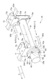
図3は、電気ヒータ21を示す斜視図である。
FIG. 3 is a perspective view showing the
電気ヒータ21はヒータ部63と、このヒータ部63が挿入される筒部61とを備え、筐体50内に配置されている。具体的には、この電気ヒータ21は、第1〜第4の取付金具71〜74によって、上記鋼材59d,59eに吊り下げられている。上記挿入用スペース80(図2参照)は、筐体50内において、ヒータ部63が筒部61に挿入される方向(図中Y方向)の手前に配置されている。ヒータ部63は、電気配線が結線されるターミナル部63aと、このターミナル部63aの一端に設けられる第1のフランジ63bと、棒状のヒータ本体63cとを備える。本実施形態では、この棒状のヒータ本体63cとしてシーズヒータが用いられる。
The
また、筒部61は、腐食性及び加工の容易性から銅または銅合金が使用され、この筒部61の一端は開口し、この開口の周囲には第2のフランジ61aが設けられるとともに、他端は閉塞されている。この第2のフランジ61aは、上記第1のフランジ63bと相フランジとなる。筒部61は、この筒部61内に挿入されたヒータ本体63bの挿入位置よりも下方に冷却水が流入する入口配管65aを設けるとともに、当該ヒータ本体63bの挿入位置よりも上方に冷却水が流出する出口配管65bを設けて、筒部61の下方から上方へ向けて冷却水を流す構成としている。
Moreover, copper or a copper alloy is used for the
筒部61とヒータ部63とは、O−リングまたはパッキン(不図示)を介して、フランジ接続され、第1及び第2のフランジ61a,63aの孔に、それぞれボルト66を貫通させ、この貫通したボルト66にナット68を螺合させて固定している。
The
これらのボルト66は、図4に示すように、第1取付金具71及び第2取付金具72に溶接などの手段によって植設されている。第1取付金具71は、鋼材59dと連結する連結部71aと、この連結部71aの両縁をそれぞれ略直角に折り曲げて形成される、フランジ固定部71b及び屈曲部71cとを備える。このフランジ固定部71bには、上記ボルト66が植設されているとともに、電気ヒータ21の筒部61が係合する半円状の切り欠きが形成されている。また、屈曲部71cには、上記排気マフラ6(図2参照)が連結されている。
As shown in FIG. 4, these
また、第2取付金具72は、フランジ固定部72aを備え、このフランジ固定部72aには、上記ボルト66が植設されているとともに、電気ヒータ21の筒部61が係合する半円状の切り欠きが形成されている。
The
一方、筒部61の閉塞された側は、第3取付金具73及び第4取付金具を介して、鋼材59eに支持されている。第3取付金具73は、鋼材59eと連結する連結部73aと、この連結部73aの両縁をそれぞれ略直角に折り曲げて形成される、配管支持部73b及び屈曲部73cとを備える。この配管支持部73bには、筒部63が係合する矩形の切り欠きが形成され、この切り欠きの縁部は、それぞれ略直角に折り曲げられている。また、配管支持部73bは、上記切り欠き側の側縁部を略直角に折り曲げて形成される接合部73dを備え、この接合部73dが第4取付金具と接合する。なお、屈曲部73cには、第1取付金具71の屈曲部71c同様、上記排気マフラ6(図2参照)が連結されている。
On the other hand, the closed side of the
また、第4取付金具74は、その長手方向の側縁部を略直角に折り曲げて形成されており、この第4取付金具は、第3取付金具73にねじ(不図示)で螺合させて結合している。電気ヒータ21の筒部61は、第3取付金具73及び第4取付金具74によって狭持されている。
The
筒部63からヒータ部61を取り外す場合には、外装パネル57a(図2参照)を外した後、各フランジ61a,63aを固定している複数のナット66を緩めて取り外す。この場合、フランジ61a,63aの孔を貫通しているボルト66は、第1取付金具71及び第2取付金具72に植設されているため、従来のように、ボルトを工具(例えばスパナ)で押さえながらナット68を緩める必要はなく、ナット68のみを工具で緩めればよい。ナット68を外した後、ヒータ部63を挿入スペース80に向けて(図中X方向)引き出してヒータ部61を取り外す。この場合、電気ヒータ21は冷却水の接続口58(図2参照)を設けた方向、すなわち作業スペースが確保できる方向に向けて配置されているので、ヒータ部63を引き出して、そのまま保守点検をすることができる。
When removing the
また、ヒータ部63を筒部61に取付ける場合には、ヒータ部63をY方向に移動させて、筒部61の中にヒータ63dを挿入する。その後、ヒータ部63の第1のフランジ63aの孔に、第1取付金具71及び第2取付金具72に植設されたボルト66を貫通させて、両フランジ61a,63aを接続する。その後、当該ボルト66にナット68をそれぞれ螺合させて固定する。
When the
本実施形態によれば、電気ヒータ21は、筐体50内に取付金具71〜74で取り付けられた筒部61と、この筒部61に挿入されるヒータ部63とを備え、筐体50内部にはヒータ部63を筒部61に挿入する方向の手前に、挿入用スペース80が設けられているため、外装パネル57aを外した状態で、ヒータ部63を筒部61から引き抜くことができる。これにより、このヒータ部63の保守点検を筐体50の外部で行うことができるため、当該電気ヒータ21の保守点検が容易となる。また、上記挿入用スペース80を確保しておけば、筒部61の周囲に他の機器が配置可能となるため、設計上の省スペース化による筐体50の小型化にも貢献することができる。
According to the present embodiment, the
更に、筒部61及びヒータ部63は、それぞれフランジ61a,63bを備え、これらのフランジ61a,63bをボルト66で連結している。そのため、このボルト66を外すことにより、ヒータ部63を筒部61から引き抜くことができる。この場合、このボルト68は第1取付金具71及び第2取付金具72に植設されているため、ナット68のみを1本の工具で緩めて外すだけでヒータ部63を取り外すことができる。これにより、電気ヒータ21の保守点検時において、ヒータ部63の着脱が容易にできるようになる。
Furthermore, the
更に、電気ヒータ21の筒部61には、この筒部61内に挿入されたヒータ本体63cよりも下方に冷却水が流入する入口配管65aを設けるとともに、当該ヒータ本体63cよりも上方に冷却水が流出する出口配管65bを設けて、筒部61の下方から上方へ向けて冷却水を流す構成としているため、筒部61の中には常時冷却水が充填されている。これによれば、ヒータ本体63cと冷却水とが常時熱交換することができ、ヒータ本体63cが空焚きによって損傷することを防止できる。
Further, the
以上、本発明を上記実施の形態に基づいて説明したが、本発明はこれに限定されるものではない。 As mentioned above, although this invention was demonstrated based on the said embodiment, this invention is not limited to this.
例えば、本実施形態では、筐体50内にコージェネレーション装置100の一部の機器を配置した構成について説明しているが、これに限らず、筐体50内にすべての機器を配置する構成としても良い。
For example, in the present embodiment, a configuration in which some devices of the
1 ガスエンジン(内燃機関)
11 発電機
21 電気ヒータ
22 熱回収熱交換器
24 放熱器
50 筐体
61 筒部
61a フランジ
63 ヒータ部
63a ターミナル部
63b フランジ
63c ヒータ本体
65a 入口配管
65b 出口配管
66 ボルト
68 ナット
71 第1取付金具
72 第2取付金具
80 挿入スペース
100 コージェネレーション装置
1 Gas engine (internal combustion engine)
DESCRIPTION OF
Claims (2)
前記電気ヒータが、前記筐体内に取付金具で取り付けられ冷却水が循環する筒部と、この筒部内に挿入されるヒータ本体を有するヒータ部とを備え、
前記筐体内には、前記ヒータ部の挿入方向の手前に挿入用スペースを配置し、
前記筒部に第1のフランジを備え、前記ヒータ部に第1のフランジの相フランジとなる第2のフランジを備え、これらの第1及び第2のフランジをボルトで連結し、
前記ボルトは、前記取付金具に植設されており、このボルトに螺合するナットを緩めることにより、前記第1及び第2のフランジの連結を解除可能な構成としたことを特徴とするコージェネレーション装置。 The housing includes an internal combustion engine and a generator driven by the internal combustion engine, and includes a heat recovery heat exchanger that circulates cooling water of the internal combustion engine and gives heat of the circulating cooling water to the outside, In the cogeneration apparatus provided with an electric heater that is provided in the path of the cooling water and consumes the electric power generated by the generator to give heat to the cooling water,
The electric heater is provided with a cylindrical portion that is attached with a mounting bracket in the casing and through which cooling water circulates, and a heater portion that has a heater body that is inserted into the cylindrical portion,
In the housing, an insertion space is arranged in front of the insertion direction of the heater part ,
The cylindrical portion includes a first flange, the heater portion includes a second flange that is a companion flange of the first flange, and the first and second flanges are connected by bolts,
The said bolt is planted in the said mounting bracket, It was set as the structure which can cancel | release connection of the said 1st and 2nd flange by loosening the nut screwed together in this bolt. apparatus.
Priority Applications (1)
| Application Number | Priority Date | Filing Date | Title |
|---|---|---|---|
| JP2003394378A JP4090426B2 (en) | 2003-11-25 | 2003-11-25 | Cogeneration equipment |
Applications Claiming Priority (1)
| Application Number | Priority Date | Filing Date | Title |
|---|---|---|---|
| JP2003394378A JP4090426B2 (en) | 2003-11-25 | 2003-11-25 | Cogeneration equipment |
Publications (2)
| Publication Number | Publication Date |
|---|---|
| JP2005156004A JP2005156004A (en) | 2005-06-16 |
| JP4090426B2 true JP4090426B2 (en) | 2008-05-28 |
Family
ID=34720461
Family Applications (1)
| Application Number | Title | Priority Date | Filing Date |
|---|---|---|---|
| JP2003394378A Expired - Fee Related JP4090426B2 (en) | 2003-11-25 | 2003-11-25 | Cogeneration equipment |
Country Status (1)
| Country | Link |
|---|---|
| JP (1) | JP4090426B2 (en) |
-
2003
- 2003-11-25 JP JP2003394378A patent/JP4090426B2/en not_active Expired - Fee Related
Also Published As
| Publication number | Publication date |
|---|---|
| JP2005156004A (en) | 2005-06-16 |
Similar Documents
| Publication | Publication Date | Title |
|---|---|---|
| JP5234693B2 (en) | Construction machinery | |
| CN102197206B (en) | Engine generator | |
| KR100946490B1 (en) | Heat / water management system module of fuel cell vehicle | |
| EP3112538A1 (en) | Construction machine | |
| KR100853456B1 (en) | Indoor unit of air conditioner | |
| CN219577641U (en) | Liquid cooling heat exchange device | |
| JP2005156004A (en) | Co-generation device | |
| JP7433478B2 (en) | Heat pump water heater, heat pump device equipped with a heat pump water heater, and method for assembling a heat pump water heater | |
| CN113133266A (en) | Cooling device | |
| US5778832A (en) | Modular radiator for an engine-generator set | |
| EP1752728A2 (en) | Heat-storage unit and operation method of heat-storage unit | |
| JP5595053B2 (en) | Heat source unit and assembly method thereof | |
| CN209888667U (en) | Integrated fuel cell power generation system and electric vehicle using same | |
| JP4811864B2 (en) | Cooling system | |
| JP5567845B2 (en) | Hot water storage system | |
| CN222976911U (en) | Container type fuel power generation device | |
| JP6272524B1 (en) | Fuel cell system | |
| CN220981672U (en) | Cooling water circulation system and shipboard laboratory | |
| JP4465716B2 (en) | Electric water heater | |
| JP2019128114A (en) | Hot water heating device | |
| CN104279750B (en) | Hot-water storage unit and hot water supply apparatus | |
| JP2012219719A (en) | Construction machine | |
| CN218977045U (en) | Casing device, power assembly and electric working machine | |
| CN223750661U (en) | A vehicle-mounted hydrogen storage cylinder mounting frame and a solid hydrogen storage device | |
| JP2000015005A (en) | Deaerator |
Legal Events
| Date | Code | Title | Description |
|---|---|---|---|
| A621 | Written request for application examination |
Free format text: JAPANESE INTERMEDIATE CODE: A621 Effective date: 20060825 |
|
| A977 | Report on retrieval |
Free format text: JAPANESE INTERMEDIATE CODE: A971007 Effective date: 20070918 |
|
| A131 | Notification of reasons for refusal |
Free format text: JAPANESE INTERMEDIATE CODE: A131 Effective date: 20071016 |
|
| A521 | Written amendment |
Free format text: JAPANESE INTERMEDIATE CODE: A523 Effective date: 20071210 |
|
| TRDD | Decision of grant or rejection written | ||
| A01 | Written decision to grant a patent or to grant a registration (utility model) |
Free format text: JAPANESE INTERMEDIATE CODE: A01 Effective date: 20080129 |
|
| A61 | First payment of annual fees (during grant procedure) |
Free format text: JAPANESE INTERMEDIATE CODE: A61 Effective date: 20080226 |
|
| FPAY | Renewal fee payment (event date is renewal date of database) |
Free format text: PAYMENT UNTIL: 20110307 Year of fee payment: 3 |
|
| LAPS | Cancellation because of no payment of annual fees |