JP4100104B2 - Idle stop vehicle control device - Google Patents
Idle stop vehicle control device Download PDFInfo
- Publication number
- JP4100104B2 JP4100104B2 JP2002261092A JP2002261092A JP4100104B2 JP 4100104 B2 JP4100104 B2 JP 4100104B2 JP 2002261092 A JP2002261092 A JP 2002261092A JP 2002261092 A JP2002261092 A JP 2002261092A JP 4100104 B2 JP4100104 B2 JP 4100104B2
- Authority
- JP
- Japan
- Prior art keywords
- motor
- engine
- idle stop
- rotation speed
- rotational speed
- Prior art date
- Legal status (The legal status is an assumption and is not a legal conclusion. Google has not performed a legal analysis and makes no representation as to the accuracy of the status listed.)
- Expired - Fee Related
Links
Images
Classifications
-
- Y—GENERAL TAGGING OF NEW TECHNOLOGICAL DEVELOPMENTS; GENERAL TAGGING OF CROSS-SECTIONAL TECHNOLOGIES SPANNING OVER SEVERAL SECTIONS OF THE IPC; TECHNICAL SUBJECTS COVERED BY FORMER USPC CROSS-REFERENCE ART COLLECTIONS [XRACs] AND DIGESTS
- Y02—TECHNOLOGIES OR APPLICATIONS FOR MITIGATION OR ADAPTATION AGAINST CLIMATE CHANGE
- Y02T—CLIMATE CHANGE MITIGATION TECHNOLOGIES RELATED TO TRANSPORTATION
- Y02T10/00—Road transport of goods or passengers
- Y02T10/60—Other road transportation technologies with climate change mitigation effect
- Y02T10/64—Electric machine technologies in electromobility
-
- Y—GENERAL TAGGING OF NEW TECHNOLOGICAL DEVELOPMENTS; GENERAL TAGGING OF CROSS-SECTIONAL TECHNOLOGIES SPANNING OVER SEVERAL SECTIONS OF THE IPC; TECHNICAL SUBJECTS COVERED BY FORMER USPC CROSS-REFERENCE ART COLLECTIONS [XRACs] AND DIGESTS
- Y02—TECHNOLOGIES OR APPLICATIONS FOR MITIGATION OR ADAPTATION AGAINST CLIMATE CHANGE
- Y02T—CLIMATE CHANGE MITIGATION TECHNOLOGIES RELATED TO TRANSPORTATION
- Y02T10/00—Road transport of goods or passengers
- Y02T10/60—Other road transportation technologies with climate change mitigation effect
- Y02T10/7072—Electromobility specific charging systems or methods for batteries, ultracapacitors, supercapacitors or double-layer capacitors
-
- Y—GENERAL TAGGING OF NEW TECHNOLOGICAL DEVELOPMENTS; GENERAL TAGGING OF CROSS-SECTIONAL TECHNOLOGIES SPANNING OVER SEVERAL SECTIONS OF THE IPC; TECHNICAL SUBJECTS COVERED BY FORMER USPC CROSS-REFERENCE ART COLLECTIONS [XRACs] AND DIGESTS
- Y02—TECHNOLOGIES OR APPLICATIONS FOR MITIGATION OR ADAPTATION AGAINST CLIMATE CHANGE
- Y02T—CLIMATE CHANGE MITIGATION TECHNOLOGIES RELATED TO TRANSPORTATION
- Y02T10/00—Road transport of goods or passengers
- Y02T10/60—Other road transportation technologies with climate change mitigation effect
- Y02T10/72—Electric energy management in electromobility
Landscapes
- Output Control And Ontrol Of Special Type Engine (AREA)
- Control Of Vehicle Engines Or Engines For Specific Uses (AREA)
- Combined Controls Of Internal Combustion Engines (AREA)
- Electric Propulsion And Braking For Vehicles (AREA)
- Control Of Electric Motors In General (AREA)
Description
【0001】
【発明の属する技術分野】
本発明は、アイドルストップ時に生じる車両振動を抑制するアイドルストップ車両の制御装置に関する。
【0002】
【従来の技術】
交差点等における一時停止時にアイドリングをストップするアイドルストップ車両において、アイドルストップ時に発生する車両振動を抑制する装置が知られている。例えば、特開2000−316205号公報に開示されている車両用動力装置では、エンジンが停止動作に入った時に、発電機を発電状態としてエンジンに負荷を与えて、エンジンの回転数を素早く変化させることにより、エンジンと車体の共振点を素早く通過させて、車両振動が発生するのを抑制している。
【0003】
【特許文献1】
特開2000−316205号公報
【0004】
【発明が解決しようとする課題】
しかしながら、従来の振動抑制方法では、エンジン停止時に負荷を与えてエンジンの回転数を素早く低下させるようにしているだけであるので、エンジンが停止する直前の極低回転領域では、振動を抑制することができない可能性があった。
【0005】
本発明の目的は、アイドルストップ時に、エンジンの極低回転領域における車両振動を抑制するアイドルストップ車両の制御装置を提供することにある。
【0006】
【課題を解決するための手段】
(1)エンジンと、エンジンと連結されたモータとを備えるアイドルストップ車両の制御装置は、所定の条件が満たされた時にエンジンを停止させるためのアイドルストップ指令を出力するアイドルストップ指令出力手段と、モータを制御する制御手段と、モータの回転速度を検出する回転速度検出手段とを備える。制御手段は、アイドルストップ指令が出力された後、モータの回転速度が所定回転速度より大きい場合には第1の制御ゲインにてモータを制御し、モータの回転速度が所定回転速度より小さい場合には、第1の制御ゲインより大きい第2の制御ゲインにてモータを制御することにより、上記目的を達成する。
(2)エンジンと、エンジンと連結されたモータとを備えるアイドルストップ車両の制御装置は、所定の条件が満たされた時にアイドルストップ指令を出力するアイドルストップ指令出力手段と、モータの回転速度を検出するモータ回転速度検出手段と、エンジンの回転速度を検出するエンジン回転速度検出手段と、モータの回転速度を用いてモータの回転速度フィードバック制御を行う制御手段とを備える。制御手段は、アイドルストップ指令が出力された後、モータの回転速度が所定回転速度以下の場合には、エンジンの回転速度を用いてモータの回転速度フィードバック制御を行うことにより、上記目的を達成する。
(3)エンジンと、エンジンと連結されたモータとを備えるアイドルストップ車両の制御装置は、所定の条件が満たされた時にアイドルストップ指令を出力するアイドルストップ指令出力手段と、モータの回転速度を検出するモータ回転速度検出手段と、モータを駆動するためのトルク指令値を算出するトルク指令値算出手段とを備える。トルク指令値算出手段は、アイドルストップ指令が出力された後、モータの回転速度が所定回転速度以下の場合には、エンジンフリクションを補償する補正トルク値も算出することにより、最終的なトルク指令値を算出し、上記目的を達成する。
(4)エンジンと、エンジンと連結されたモータとを備えるアイドルストップ車両の制御装置は、所定の条件が満たされた時にアイドルストップ指令を出力するアイドルストップ指令出力手段と、モータの回転速度を検出するモータ回転速度検出手段と、モータの回転速度指令値を算出する回転速度指令値算出手段とを備える。回転速度指令値算出手段は、アイドルストップ指令が出力されると、モータ回転速度検出手段により検出されるモータの回転速度が所定回転速度までは第1の変化率でモータの回転速度を低下させ、所定回転速度からは第1の変化率より小さい第2の変化率でモータの回転速度を低下させる回転速度指令値を算出することを特徴とする、上記目的を達成する。
【0007】
【発明の効果】
本発明によれば、次のような効果を奏する。
(1)請求項1の発明によれば、アイドルストップ指令が出力された後、モータの回転速度が所定回転速度より大きい場合には第1の制御ゲインにてモータを制御し、モータの回転速度が所定回転速度より小さい場合には、第1の制御ゲインより大きい第2の制御ゲインにてモータを制御するので、低回転速度領域におけるモータ制御の応答性を向上させて、エンジン振動を抑制することができる。
(2)請求項3の発明によれば、アイドルストップ指令が出力された後、モータの回転速度が所定回転速度以下の場合には、エンジンの回転速度を用いてモータの回転速度フィードバック制御を行うので、振動の原因となるエンジン回転速度を直接用いることにより、エンジン振動を効果的に抑制することができる。
(3)請求項4の発明によれば、アイドルストップ指令が出力された後、モータの回転速度が所定回転速度以下の場合には、エンジンフリクションを補償する補正トルク値を算出することによって最終的なトルク指令値を算出するので、エンジン振動を効果的に抑制することができる。
(4)請求項7の発明によれば、アイドルストップ指令が出力されると、モータの回転速度が所定回転速度までは第1の変化率でモータの回転速度を低下させ、所定回転速度からは第1の変化率より小さい第2の変化率でモータの回転速度を低下させる回転速度指令値を算出するので、エンジンとモータの慣性力を小さくしてエンジン振動を抑制することができる。
【0008】
【発明の実施の形態】
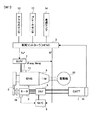
図1は、本発明による制御装置を適用した一実施の形態のアイドルストップ車両の主要部の構成を示す図である。このアイドルストップ車両は、エンジン1の駆動力が自動変速機9を介して駆動輪10に伝達されることにより走行する。
【0009】
車両コントローラ(HCM)2は、エンジン1の始動指令・停止指令およびトルク指令を後述するエンジンコントローラ(ECM)3に出力するとともに、回転速度指令を後述するモータコントローラ(M/C)4に出力する。エンジン1の始動指令・停止指令には、信号待ち等により車両が一時的に停止する場合のアイドルストップの作動・解除指令が含まれる。後述するように、アイドルストップ時には、エンジン振動を抑制する回転速度指令値を算出して、モータコントローラ4に出力する。
【0010】
車両コントローラ2には、図示しないアクセルペダルの操作量を検出するアクセルセンサ12、図示しないブレーキペダルの操作量を検出するブレーキセンサ13、車両の速度を検出する車速センサ14が接続されている。エンジンコントローラ3に出力するエンジントルク指令値Te*は、各センサ12〜14で検出された検出値に基づいて算出される。
【0011】
車両コントローラ2には、さらに、バッテリ7の充電率(SOC)を検出する電圧センサ15が接続されている。車両コントローラ2は、各センサ12〜15で検出された検出値に基づいて、アイドルストップの実施/解除を決定する。具体的には、車速センサ14で検出した車速が所定車速以下であり、アクセルペダル操作量が0、ブレーキペダルがオン、かつ、バッテリ7のSOCが所定値以上の全ての条件が満たされた時に、アイドルストップを実施する。また、アイドルストップしている状態からいずれかの条件が満たされなくなった時に、アイドルストップを解除する。
【0012】
エンジンコントローラ3は、車両コントローラ2から送られてくるエンジン始動/停止指令に基づいて、エンジン1の始動/停止制御を行う。また、車両コントローラ2から送られてくるエンジントルク指令値Te*に基づいて、不図示のスロットルバルブ開閉装置、燃料噴射装置および点火時期制御装置を制御する。エンジンコントローラ3は、また、クランク角センサ11から送信される信号に基づいて、エンジン1のクランク角θengおよびエンジン回転速度Nengを算出し、モータコントローラ4に出力する。
【0013】
モータコントローラ4は、車両コントローラ2から送られてくる回転速度指令N*と、レゾルバ16で検出されるモータ回転速度Nmとに基づいて、フィードバック演算処理を行うことにより、モータ5を駆動するための最終的なトルク指令値T*を算出する。後述するように、車両のアイドルストップ時には、エンジン振動を抑制するトルク指令値T*を算出する。
【0014】
インバータ6は、モータコントローラ4にて算出される電圧指令値V*に基づいて、バッテリ7の直流電力を3相交流電力に変換してモータ5に供給し、モータ5を駆動(力行)運転する。モータ5は、プーリー&ベルト動力伝達機構8を介してエンジン1と連結されており、エンジン1を始動するために用いられるとともに、図示しない補機を駆動する。また、モータ5は、バッテリ7の電力が少なくなった場合には、モータコントローラ4からの指令に基づいて、エンジン1を動力源とする回生運転により発電も行う。発電された電力は、インバータ6で直流電力に変換されて、バッテリ7に蓄電される。
【0015】
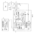
図2は、車両コントローラ2およびモータコントローラ4で行われる制御の詳細内容を示す制御システム図である。初めに、車両コントローラ2で行われる制御内容について説明する。
【0016】
上述したアイドルストップのための条件が満たされると、車両コントローラ2は、エンジン1を停止させるために、モータ5の回転速度指令N*をモータコントローラ4に出力する。回転速度指令N*は、回転速度指令演算部2aで演算する。回転速度指令演算部2aは、エンジン回転速度が所定回転速度NLまで低下する時のモータ5の回転速度指令N*の低下速度と、所定回転速度NL以下になった時の回転速度指令N*の低下速度とを異なる値とする。
【0017】
すなわち、アイドルストップを開始した時の時刻をt1、エンジン回転速度がアイドリング時のエンジン回転速度Niから所定回転速度NLに低下した時の時刻をt2、エンジン1が停止した時の時刻をt3とすると、モータ5の回転速度指令N*は、次式(1)にて表すことができる。

【0018】
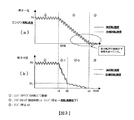
図3(a)は、アイドルストップを開始してから、一定の低下速度による回転速度指令N*を出力する場合のエンジン1の目標回転速度と実回転速度との関係を示す図である。この場合、エンジン回転速度の低下速度が大きいため、エンジン1が停止する間際にエンジン1とモータ5の慣性力によって、エンジン1の実回転速度が目標回転速度に対してアンダーシュートし、エンジン停止後に振動が持続する場合がある。この振動を防止するために、モータトルクを大きくすることによって対応することも考えられるが、モータの外形寸法が大きくなってしまう。
【0019】
図3(b)は、エンジン1の停止間際における回転速度指令N*の低下速度を小さくする場合のエンジン1の目標回転速度と実回転速度との関係を示す図である。時刻t1でアイドルストップを開始してから、時刻t2までにエンジン回転速度をNLまで低下させ、その後徐々に0まで低下させる。モータ5の回転速度指令N*は、図3(b)に示すエンジン1の目標回転速度に比例(K倍)する値となる。このように、モータ5の回転速度指令N*の低下速度を所定回転速度K・NLまでは第1の低下速度とし、所定回転速度K・NL以下では第1の低下速度より小さい第2の低下速度とすることにより、エンジン1とモータ5の慣性力を小さくして、アイドルストップ指令後のエンジン振動を低減する。
【0020】
モータコントローラ4は、内部で行う演算処理の機能上、回転速度制御部4aと、回転速度フィードバック選択部4bと、回転速度ゲイン切換部4cと、エンジンフリクション演算部4dと、電流制御部4eと、減算部4fとを備える。回転速度制御部4aは、車両コントローラ2から送られてくる回転速度指令N*と後述する回転速度フィードバック指令Nとに基づいて、回転速度制御を行い、トルク指令値Trefを算出する。回転速度制御は、次式(2)による比例・積分制御(PI制御)とする。
Tref=Kp(N*−N)+Ki∫(N*−N)dt …(2)
ただし、Kpは比例ゲイン、Kiは積分ゲインであり、後述する回転速度制御ゲイン切換部4cから送られてくる。
【0021】
回転速度フィードバック選択部4bは、レゾルバ16で検出されるモータ回転速度Nmの大きさに基づいて、回転速度制御部4aで行われるPI制御で用いる回転速度フィードバック指令Nを選択する。すなわち、モータ回転速度Nmが所定回転速度K・NLより大きい場合は、回転速度フィードバック指令Nとしてモータ回転速度Nmを選択し、モータ回転速度NmがK・NL以下の場合は、K・Nengを選択する。従って、回転速度フィードバック指令Nは、次式(3)で表せる。なお、エンジン回転速度Nengは、上述したように、エンジンコントローラ3から送られる。
N=Nm (N>K・NL)
N=K・Neng (N≦K・NL) …(3)
【0022】
モータ5は、プーリー&ベルト動力伝達機構8を介してエンジン1と連結されているので、エンジン回転速度Nengとモータ回転速度Nmとの間には、必ずしもNm=K・Nengの関係が成り立たない。従って、モータ5の回転速度制御を行うに際し、エンジン1の低回転速度領域において、回転速度フィードバック指令Nとしてエンジン回転速度Nengを直接用いることにより、プーリー&ベルト動力伝達機構8の影響を受けない制御が可能となる。すなわち、振動の原因となるエンジン回転速度Nengの変動を直接制御することにより、エンジン振動を抑制する。なお、エンジン1の低回転速度領域では回転速度変動周期が長いので、エンジンコントローラ3からモータコントローラ4にエンジン回転速度Nengが送信される時間、すなわち通信時間が回転速度制御に及ぼす影響は小さい。
【0023】
回転速度制御ゲイン切換部4cは、レゾルバ16で検出されるモータ回転速度Nmの大きさに基づいて、次式(4)により、回転速度制御部4aで行われるPI制御で用いられる比例ゲインKpと積分ゲインKiとを切り換える。
Kp=Kp1、Ki=Ki1 (Nm>K・NL)
Kp=Kp2、Ki=Ki2 (Nm≦K・NL) …(4)
ただし、Kp1<Kp2、Ki1<Ki2である。
【0024】
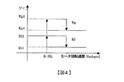
図4は、モータ回転速度Nmと、比例ゲインKpおよび積分ゲインKiとの関係を示す図である。図4では、ゲインの切り換えに際し、ヒステリシスを設けているが、モータ回転速度Nmが低下して所定回転速度K・NL以下になると、式(4)に示すように、比例ゲインKpおよび積分ゲインKiを共に大きくしている。
【0025】
式(4)に示すように、エンジン1の低回転速度領域において、モータ5のPI制御の制御ゲインを大きくすることにより、式(2)により算出されるトルク指令値Trefは大きくなる。これにより、モータ制御の応答性を向上させて、エンジン1の振動を抑制することができる。一方、振動の問題が発生しにくい高回転領域では、制御ゲインを小さくすることにより、回転速度偏差(N*−N)に対するトルク指令値Trefを小さくして、バッテリ7からモータ5に供給される電力量(消費電力)を少なくする。
【0026】
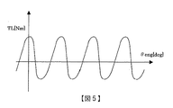
エンジンフリクション演算部4dは、まず、エンジン1のクランク角θengに基づいて、エンジンフリクションTLを算出する。クランク角θengとエンジンフリクションTLとの間には、図5に示す関係があるので、クランク角θengとエンジンフリクションTLとを対応付けたテーブルを予め用意しておき、このテーブルを用いてエンジンフリクションTLを算出する。
【0027】
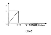
次に、エンジンフリクション演算部4dは、モータ回転速度Nmに対する減衰率G(0≦G≦1)を求める。本実施の形態では、図6に示すように、モータ回転速度Nmと減衰率Gとを対応付けたテーブルを予め用意しておき、このテーブルを用いて減衰率Gを算出する。減衰率Gを式で表すと、次式(5)のようになる。
G=0 (Nm>K・NL)
G=Nm/(K・NL) (Nm≦K・NL) …(5)
【0028】
エンジンフリクション演算部4dは、上述したエンジンフリクションTLと減衰率Gとを掛け合わせることにより、エンジンフリクションを補償するためのトルク補正値TL1を算出する。すなわち、トルク補正値TL1は、次式(6)で表せる。
TL1=TL×G …(6)
【0029】
減算部4fは、回転速度制御部4aで算出されるトルク指令値Trefからトルク補正値TL1を減算することにより、最終的なトルク指令値T*を算出する。すなわち、モータ回転速度NmがK・NL以下の時には、エンジンフリクションTLを補償するトルク補正値TL1を算出することによって最終的なトルク指令値T*を求めるので、エンジン1の振動を効果的に抑制することができる。ここで、減衰率Gが一定の値であると、エンジン1が停止する間際には、テーブル化したフリクション値と実際のエンジンフリクションとの差に起因して、逆に振動を持続させてしまう可能性がある。従って、本実施の形態では、モータ回転速度Nmに比例させて、モータ回転速度Nmが小さくなるほど減衰率Gが小さくなるようにしている。これにより、エンジン停止間際でのエンジン回転速度の振動持続を小さくすることができる。
【0030】
なお、エンジン1の低回転速度領域では回転速度変動周期が長いので、エンジンコントローラ3からモータコントローラ4にエンジン1のクランク角θengが送信される時間、すなわち通信時間がトルク補正値演算に及ぼす影響は小さい。
【0031】
電流制御部4eは、減算部4fから出力される最終的なトルク指令値T*に基づいて、インバータ6に出力するための電圧指令値V*を算出する。インバータ6は、電圧指令値V*に基づいて、バッテリ7の直流電力を3相交流電力に変換してモータ5に供給し、モータ5を駆動する。
【0032】
本実施の形態におけるアイドルストップ車両の制御装置による制御方法、すなわち、アイドルストップ指令時に、エンジン1の低回転速度領域におけるエンジン振動の抑制方法についてまとめておく。
【0033】
(1)車両コントローラ2の回転速度指令演算部2aは、アイドルストップ指令が出力された後のモータ5の回転速度指令N*の低下速度を所定回転速度K・NLまでは第1の低下速度とし、所定回転速度K・NL以下では第1の低下速度より小さい第2の低下速度とした。これにより、車両の乗員がエンジン振動を体感しやすい低回転速度領域におけるエンジン1の速度変化を小さくして、エンジン1とモータ5の慣性力を小さくし、エンジン振動を低減することができる。
【0034】
(2)モータコントローラ4の回転速度フィードバック選択部4bは、モータ5の回転速度フィードバック制御に用いる回転速度フィードバック指令Nとして、モータ5の回転速度Nmが所定回転速度K・NLより大きいときは回転速度Nmを選択し、所定回転速度K・NL以下のときはK・Nengを用いた。すなわち、アイドルストップ時に、モータ5の回転速度Nmが所定回転速度K・NL以下のときにエンジン回転速度Nengを用いてモータ5の回転速度制御を行うので、エンジン1とモータ5との間に介在しているプーリー&ベルト動力伝達機構8の影響を受けない制御が可能となり、エンジン1の振動を効果的に抑制することができる。
【0035】
(3)モータコントローラ4の回転速度制御ゲイン切換部4cは、モータ5の回転速度Nmが所定回転速度K・NL以下になると、モータ5の回転速度制御で用いられる制御ゲイン、すなわち、比例ゲインKpと積分ゲインKiの値を大きくした。これにより、アイドルストップ時の低回転速度領域におけるモータ制御の応答性を向上させて、エンジン1の振動を低減させることができる。
【0036】
(4)モータコントローラ4のエンジンフリクション演算部4dは、モータ5の回転速度Nmが所定回転速度K・NL以下の場合に、エンジン1のクランク角θengに基づくエンジンフリクションTLを補償するためのトルク補正値TL1を算出する。モータ5を駆動するための最終的なトルク指令値T*は、モータ5の回転速度制御により算出されるトルク指令値Trefからトルク補正値TL1を減算することにより算出されるので、モータ回転速度NmがK・NL以下の時には、エンジンフリクションTLを補償することにより、エンジン1の振動を効果的に抑制することができる。また、モータ5の回転速度Nmの低下に伴ってトルク補正値TL1を小さくすることにより、エンジン停止間際におけるエンジン回転速度の振動持続を低減することができる。
【0037】
本発明は、上述した一実施の形態に限定されることはない。例えば、上述した一実施の形態では、回転速度指令演算部2a、回転速度フィードバック選択部4b、回転速度制御ゲイン切換部4c、および、エンジンフリクション演算部4dのそれぞれにおいて、アイドルストップ時のエンジン1の低回転速度領域におけるエンジン振動を抑制するための制御を行ったが、いずれか1つの制御を行うようにしてもいし、複数の制御を組み合わせるようにしてもよい。
【0038】
回転速度制御ゲイン切換部4cは、モータ5の回転速度Nmが所定回転速度K・NL以下になると、比例ゲインKpと積分ゲインKiの値をそれぞれ大きくしたが、例えば、比例ゲインKpの値のみを大きくすることもできる。また、回転速度制御部4aにおいて、モータ5の回転速度に対してPID制御を行うような場合には、比例ゲインKpと積分ゲインKiとともに、微分ゲインKdの値を大きくすることもできる。すなわち、モータ5の回転速度Nmが所定回転速度K・NL以下になったときに、モータ制御の応答性を向上させるようにすればよい。
【0039】
回転速度指令演算部2a、回転速度フィードバック選択部4b、回転速度制御ゲイン切換部4c、および、エンジンフリクション演算部4dは、モータの回転速度Nmの大きさに基づいてそれぞれ制御を行っているが、エンジン1とモータ5の回転速度比が一定(K)であることから、エンジンの回転速度Nengの大きさに基づいて制御を行うこともできる。
【0040】
モータ5はエンジン1とプーリー&ベルト動力伝達機構8を介して連結されているものとして説明したが、エンジン1と直結されているものでもよい。また、モータ5の用途により本発明が限定されることも無い。
【0041】
特許請求の範囲の構成要素と一実施の形態の構成要素との対応関係は次の通りである。すなわち、車両コントローラ2がアイドルストップ指令出力手段および回転速度指令値算出手段を、レゾルバ16がモータ回転速度検出手段を、エンジンコントローラ3がエンジン回転速度検出手段を、モータコントローラ4が制御手段およびトルク指令値算出手段をそれぞれ構成する。なお、本発明の特徴的な機能を損なわない限り、各構成要素は上記構成に限定されるものではない。
【図面の簡単な説明】
【図1】本発明による制御装置を適用した一実施の形態のアイドルストップ車両の主要部の構成を示す図
【図2】車両コントローラおよびモータコントローラの制御システム構成を示す図
【図3】図3(a)は、一定の低下速度による回転速度指令N*を出力する場合のエンジンの目標回転速度と実回転速度との関係を示す図、図3(b)はエンジンの停止間際における回転速度指令N*の低下速度を小さくする場合のエンジンの目標回転速度と実回転速度との関係を示す図
【図4】モータの回転速度と比例ゲインKpおよび積分ゲインKiとの関係を示す図
【図5】エンジンのクランク角とエンジンフリクショントルクとの関係を示す図
【図6】モータ回転速度とトルク補正値TL1を算出する際に用いる減衰率Gとの関係を示す図
【符号の説明】
1…エンジン、2…車両コントローラ、3…エンジンコントローラ、4…モータコントローラ、5…モータ、6…インバータ、7…バッテリ、8…プーリー&ベルト動力伝達機構、9…自動変速機、10…駆動輪、11…クランク角センサ、12…アクセルセンサ、13…ブレーキセンサ、14…車速センサ、15…電圧センサ、16…レゾルバ、2a…回転速度指令演算部、4a…回転速度制御部、4b…回転速度フィードバック選択部、4c…回転速度制御ゲイン切換部、4d…エンジンフリクション演算部、4e…電流制御部、4f…減算部[0001]
BACKGROUND OF THE INVENTION
The present invention relates to a control device for an idle stop vehicle that suppresses vehicle vibration that occurs during idle stop.
[0002]
[Prior art]
In an idle stop vehicle that stops idling when temporarily stopped at an intersection or the like, a device that suppresses vehicle vibration that occurs during idle stop is known. For example, in the vehicular power unit disclosed in Japanese Patent Laid-Open No. 2000-316205, when the engine enters a stop operation, the generator is set in a power generation state and a load is applied to the engine to quickly change the engine speed. As a result, the vibration point of the vehicle is suppressed by quickly passing through the resonance point between the engine and the vehicle body.
[0003]
[Patent Document 1]
Japanese Patent Laid-Open No. 2000-316205
[Problems to be solved by the invention]
However, in the conventional vibration suppression method, only a load is applied when the engine is stopped to quickly reduce the engine speed. Therefore, vibration is suppressed in an extremely low rotation region immediately before the engine stops. There was a possibility that could not.
[0005]
An object of the present invention is to provide a control device for an idle stop vehicle that suppresses vehicle vibration in an extremely low rotation region of the engine at the time of idle stop.
[0006]
[Means for Solving the Problems]
(1) An idle stop vehicle control device comprising an engine and a motor coupled to the engine, idle stop command output means for outputting an idle stop command for stopping the engine when a predetermined condition is satisfied, Control means for controlling the motor and rotation speed detection means for detecting the rotation speed of the motor are provided. The control means controls the motor with the first control gain when the rotational speed of the motor is greater than the predetermined rotational speed after the idle stop command is output, and when the rotational speed of the motor is smaller than the predetermined rotational speed. Achieves the above object by controlling the motor with a second control gain larger than the first control gain.
(2) An idle stop vehicle control device comprising an engine and a motor coupled to the engine detects an idle stop command output means for outputting an idle stop command when a predetermined condition is satisfied, and detects the rotational speed of the motor. A motor rotation speed detection means for detecting the rotation speed of the engine, and a control means for performing feedback control of the rotation speed of the motor using the rotation speed of the motor. The control means achieves the above-mentioned object by performing the rotational speed feedback control of the motor using the rotational speed of the engine when the rotational speed of the motor is equal to or lower than the predetermined rotational speed after the idle stop command is output. .
(3) An idle stop vehicle control device comprising an engine and a motor coupled to the engine detects an idle stop command output means for outputting an idle stop command when a predetermined condition is satisfied, and detects the rotational speed of the motor. Motor rotation speed detecting means for performing the operation, and torque command value calculating means for calculating a torque command value for driving the motor. The torque command value calculation means calculates a final torque command value by calculating a correction torque value that compensates for engine friction when the rotation speed of the motor is equal to or lower than a predetermined rotation speed after the idle stop command is output. To achieve the above objective.
(4) An idle stop vehicle control device comprising an engine and a motor connected to the engine detects an idle stop command output means for outputting an idle stop command when a predetermined condition is satisfied, and detects the rotational speed of the motor. Motor rotation speed detecting means for performing rotation speed command value calculating means for calculating a motor rotation speed command value. When the idle speed stop command is output, the rotational speed command value calculating means decreases the rotational speed of the motor at a first rate of change until the rotational speed of the motor detected by the motor rotational speed detecting means reaches a predetermined rotational speed, The above object is achieved by calculating a rotational speed command value for reducing the rotational speed of the motor from the predetermined rotational speed at a second change rate smaller than the first change rate .
[0007]
【The invention's effect】
The present invention has the following effects.
(1) According to the first aspect of the present invention, after the idle stop command is output, when the rotational speed of the motor is higher than the predetermined rotational speed, the motor is controlled with the first control gain. Is smaller than the predetermined rotational speed, the motor is controlled with the second control gain that is larger than the first control gain, so that the motor control response in the low rotational speed region is improved and the engine vibration is suppressed. be able to.
(2) According to the invention of claim 3, after the idle stop command is output, when the rotational speed of the motor is equal to or lower than the predetermined rotational speed, the rotational speed feedback control of the motor is performed using the rotational speed of the engine. Therefore, the engine vibration can be effectively suppressed by directly using the engine speed that causes the vibration.
(3) According to the invention of
(4) According to the invention of
[0008]
DETAILED DESCRIPTION OF THE INVENTION
FIG. 1 is a diagram illustrating a configuration of a main part of an idle stop vehicle according to an embodiment to which a control device according to the present invention is applied. The idle stop vehicle travels when the driving force of the
[0009]
The vehicle controller (HCM) 2 outputs a start command / stop command and a torque command for the
[0010]
The
[0011]
The
[0012]
The engine controller 3 performs start / stop control of the
[0013]
The
[0014]
The inverter 6 converts the DC power of the
[0015]
FIG. 2 is a control system diagram showing the detailed contents of the control performed by the
[0016]
When the above-described conditions for idling stop are satisfied, the
[0017]
That is, the time when the idling stop is started is t1, the time when the engine speed is reduced from the engine speed Ni at idling to the predetermined speed NL is t2, and the time when the
[0018]
FIG. 3A is a diagram showing the relationship between the target rotational speed of the
[0019]
FIG. 3B is a diagram showing the relationship between the target rotational speed of the
[0020]
The
Tref = Kp (N * -N) + Ki (N * -N) dt (2)
However, Kp is a proportional gain, Ki is an integral gain, and is sent from a rotation speed control gain switching unit 4c described later.
[0021]
The rotational speed feedback selection unit 4b selects a rotational speed feedback command N used in PI control performed by the rotational speed control unit 4a based on the magnitude of the motor rotational speed Nm detected by the
N = Nm (N> K ・ NL)
N = K · Neng (N ≤ K · NL) (3)
[0022]
Since the
[0023]
The rotational speed control gain switching unit 4c is based on the magnitude of the motor rotational speed Nm detected by the
Kp = Kp1, Ki = Ki1 (Nm> K · NL)
Kp = Kp2, Ki = Ki2 (Nm ≦ K · NL) (4)
However, Kp1 <Kp2 and Ki1 <Ki2.
[0024]
FIG. 4 is a diagram showing the relationship between the motor rotation speed Nm, the proportional gain Kp, and the integral gain Ki. In FIG. 4, hysteresis is provided at the time of switching the gain. However, when the motor rotation speed Nm decreases and becomes equal to or less than the predetermined rotation speed K · NL, as shown in the equation (4), the proportional gain Kp and the integral gain Ki Both are made larger.
[0025]
As shown in Expression (4), in the low rotation speed region of the
[0026]
The engine friction calculation unit 4d first calculates the engine friction TL based on the crank angle θeng of the
[0027]
Next, the engine friction calculation unit 4d obtains an attenuation rate G (0 ≦ G ≦ 1) with respect to the motor rotation speed Nm. In the present embodiment, as shown in FIG. 6, a table in which the motor rotation speed Nm and the attenuation rate G are associated with each other is prepared in advance, and the attenuation rate G is calculated using this table. The attenuation rate G is expressed by the following equation (5).
G = 0 (Nm> K · NL)
G = Nm / (K · NL) (Nm ≦ K · NL) (5)
[0028]
The engine friction calculation unit 4d calculates a torque correction value TL1 for compensating for engine friction by multiplying the above-described engine friction TL and the damping rate G. That is, the torque correction value TL1 can be expressed by the following equation (6).
TL1 = TL × G (6)
[0029]
The subtraction unit 4f calculates a final torque command value T * by subtracting the torque correction value TL1 from the torque command value Tref calculated by the rotation speed control unit 4a. That is, when the motor rotational speed Nm is equal to or lower than K · NL, the final torque command value T * is obtained by calculating the torque correction value TL1 that compensates for the engine friction TL, so that vibration of the
[0030]
Since the rotational speed fluctuation cycle is long in the low rotational speed region of the
[0031]
The current control unit 4e calculates a voltage command value V * for output to the inverter 6 based on the final torque command value T * output from the subtraction unit 4f. The inverter 6 converts the DC power of the
[0032]
A control method by the control apparatus for the idle stop vehicle in the present embodiment, that is, a method for suppressing engine vibration in the low rotation speed region of the
[0033]
(1) The rotation speed command calculation unit 2a of the
[0034]
(2) The rotational speed feedback selection unit 4b of the
[0035]
(3) The rotational speed control gain switching unit 4c of the
[0036]
(4) The engine friction calculation unit 4d of the
[0037]
The present invention is not limited to the embodiment described above. For example, in the above-described embodiment, each of the rotation speed command calculation unit 2a, the rotation speed feedback selection unit 4b, the rotation speed control gain switching unit 4c, and the engine friction calculation unit 4d performs Although the control for suppressing the engine vibration in the low rotation speed region is performed, any one control may be performed, or a plurality of controls may be combined.
[0038]
The rotational speed control gain switching unit 4c increases the values of the proportional gain Kp and the integral gain Ki when the rotational speed Nm of the
[0039]
The rotation speed command calculation unit 2a, the rotation speed feedback selection unit 4b, the rotation speed control gain switching unit 4c, and the engine friction calculation unit 4d perform control based on the magnitude of the rotation speed Nm of the motor, respectively. Since the rotation speed ratio between the
[0040]
Although the
[0041]
The correspondence between the constituent elements of the claims and the constituent elements of the embodiment is as follows. That is, the
[Brief description of the drawings]
FIG. 1 is a diagram showing a configuration of a main part of an idle stop vehicle according to an embodiment to which a control device according to the present invention is applied. FIG. 2 is a diagram showing a control system configuration of a vehicle controller and a motor controller. FIG. 3A is a diagram showing the relationship between the target engine speed and the actual engine speed when the engine speed command N * with a constant reduction speed is output, and FIG. 3B shows the engine speed command just before the engine stops. FIG. 4 is a diagram showing the relationship between the target engine speed and the actual engine speed when the decrease rate of N * is reduced. FIG. 4 is a diagram showing the relationship between the motor speed and the proportional gain Kp and integral gain Ki. FIG. 6 is a diagram showing the relationship between the engine crank angle and the engine friction torque. FIG. 6 is a diagram showing the relationship between the motor rotation speed and the damping rate G used when calculating the torque correction value TL1.
DESCRIPTION OF
Claims (7)
所定の条件が満たされた時に前記エンジンを停止させるためのアイドルストップ指令を出力するアイドルストップ指令出力手段と、
前記モータを制御する制御手段と、
前記モータの回転速度を検出するモータ回転速度検出手段とを備え、
前記制御手段は、前記アイドルストップ指令が出力された後、前記モータ回転速度検出手段にて検出された前記モータの回転速度が所定回転速度より大きい場合には第1の制御ゲインにて前記モータを制御し、前記モータの回転速度が前記所定回転速度より小さい場合には、前記第1の制御ゲインより大きい第2の制御ゲインにて前記モータを制御することを特徴とするアイドルストップ車両の制御装置。In an idle stop vehicle control device comprising an engine and a motor coupled to the engine,
Idle stop command output means for outputting an idle stop command for stopping the engine when a predetermined condition is satisfied;
Control means for controlling the motor;
Motor rotation speed detecting means for detecting the rotation speed of the motor,
When the rotation speed of the motor detected by the motor rotation speed detection means is greater than a predetermined rotation speed after the idle stop command is output, the control means controls the motor with a first control gain. And controlling the motor with a second control gain that is greater than the first control gain when the rotational speed of the motor is smaller than the predetermined rotational speed. .
前記制御手段は、前記回転速度検出手段により検出された前記モータの回転速度と目標値とを一致させるためにPI制御を行うことにより前記モータを制御し、前記制御ゲインは比例ゲインおよび積分ゲインの少なくともいずれか一方であることを特徴とするアイドルストップ車両の制御装置。The control apparatus for an idle stop vehicle according to claim 1,
The control means controls the motor by performing PI control in order to make the rotational speed of the motor detected by the rotational speed detection means coincide with a target value, and the control gain is a proportional gain and an integral gain. A control device for an idle stop vehicle, wherein the control device is at least one of the two.
所定の条件が満たされた時に前記エンジンを停止させるためのアイドルストップ指令を出力するアイドルストップ指令出力手段と、
前記モータの回転速度を検出するモータ回転速度検出手段と、
前記エンジンの回転速度を検出するエンジン回転速度検出手段と、
前記モータ回転速度検出手段により検出された前記モータの回転速度を用いて、前記モータの回転速度フィードバック制御を行う制御手段とを備え、
前記制御手段は、前記アイドルストップ指令が出力された時に、前記モータ回転速度検出手段により検出された前記モータの回転速度が所定回転速度以下の場合には、前記エンジン回転速度検出手段により検出された前記エンジンの回転速度を用いて、前記モータの回転速度フィードバック制御を行うことを特徴とするアイドルストップ車両の制御装置。In an idle stop vehicle control device comprising an engine and a motor coupled to the engine,
Idle stop command output means for outputting an idle stop command for stopping the engine when a predetermined condition is satisfied;
Motor rotation speed detection means for detecting the rotation speed of the motor;
Engine rotation speed detection means for detecting the rotation speed of the engine;
Control means for performing rotational speed feedback control of the motor using the rotational speed of the motor detected by the motor rotational speed detection means;
When the rotation speed of the motor detected by the motor rotation speed detection means is less than or equal to a predetermined rotation speed when the idle stop command is output, the control means is detected by the engine rotation speed detection means A control apparatus for an idle stop vehicle, wherein the rotational speed feedback control of the motor is performed using the rotational speed of the engine.
所定の条件が満たされた時に前記エンジンを停止させるためのアイドルストップ指令を出力するアイドルストップ指令出力手段と、
前記モータの回転速度を検出するモータ回転速度検出手段と、
前記モータを駆動するためのトルク指令値を算出するトルク指令値算出手段とを備え、
前記トルク指令値算出手段は、前記アイドルストップ指令が出力された後、前記モータ回転速度検出手段により検出された前記モータの回転速度が所定回転速度以下の場合には、エンジンフリクションを補償する補正トルク値を算出することにより、最終的なトルク指令値を算出することを特徴とするアイドルストップ車両の制御装置。In an idle stop vehicle control device comprising an engine and a motor coupled to the engine,
Idle stop command output means for outputting an idle stop command for stopping the engine when a predetermined condition is satisfied;
Motor rotation speed detection means for detecting the rotation speed of the motor;
Torque command value calculating means for calculating a torque command value for driving the motor,
The torque command value calculation means compensates for engine friction when the motor rotation speed detected by the motor rotation speed detection means is less than or equal to a predetermined rotation speed after the idle stop command is output. A control device for an idle stop vehicle, wherein a final torque command value is calculated by calculating a value.
前記トルク指令値算出手段は、前記モータの回転速度フィードバック制御を行うことにより算出されるトルク指令値と、前記補正トルク指令値とに基づいて、前記最終的なトルク指令値を算出することを特徴とするアイドルストップ車両の制御装置。The control apparatus for an idle stop vehicle according to claim 4,
The torque command value calculating means calculates the final torque command value based on a torque command value calculated by performing rotational speed feedback control of the motor and the corrected torque command value. An idle stop vehicle control device.
前記トルク指令値算出手段は、前記モータの回転速度が低下するほど前記補正トルク値を小さくすることを特徴とするアイドルストップ車両の制御装置。In the control apparatus of the idle stop vehicle according to claim 4 or 5,
The control apparatus for an idle stop vehicle, wherein the torque command value calculation means decreases the correction torque value as the rotational speed of the motor decreases.
所定の条件が満たされた時に前記エンジンを停止させるためのアイドルストップ指令を出力するアイドルストップ指令出力手段と、
前記モータの回転速度を検出するモータ回転速度検出手段と、
前記モータの回転速度指令値を算出する回転速度指令値算出手段とを備え、
前記回転速度指令値算出手段は、前記アイドルストップ指令が出力されると、前記モータ回転速度検出手段により検出される前記モータの回転速度が所定回転速度までは第1の変化率で前記モータの回転速度を低下させ、前記所定回転速度からは前記第1の変化率より小さい第2の変化率で前記モータの回転速度を低下させる回転速度指令値を算出することを特徴とするアイドルストップ車両の制御装置。In an idle stop vehicle control device comprising an engine and a motor coupled to the engine,
Idle stop command output means for outputting an idle stop command for stopping the engine when a predetermined condition is satisfied;
Motor rotation speed detection means for detecting the rotation speed of the motor;
A rotation speed command value calculating means for calculating a rotation speed command value of the motor,
When the idling stop command is output, the rotational speed command value calculating means rotates the motor at a first rate of change until the rotational speed of the motor detected by the motor rotational speed detecting means reaches a predetermined rotational speed. speed reducing the, above a predetermined rotational speed control of the idle stop vehicle and calculates the rotational speed command value to reduce the rotation speed of the motor at the first rate of change is smaller than a second change rate apparatus.
Priority Applications (1)
| Application Number | Priority Date | Filing Date | Title |
|---|---|---|---|
| JP2002261092A JP4100104B2 (en) | 2002-09-06 | 2002-09-06 | Idle stop vehicle control device |
Applications Claiming Priority (1)
| Application Number | Priority Date | Filing Date | Title |
|---|---|---|---|
| JP2002261092A JP4100104B2 (en) | 2002-09-06 | 2002-09-06 | Idle stop vehicle control device |
Publications (2)
| Publication Number | Publication Date |
|---|---|
| JP2004100504A JP2004100504A (en) | 2004-04-02 |
| JP4100104B2 true JP4100104B2 (en) | 2008-06-11 |
Family
ID=32261560
Family Applications (1)
| Application Number | Title | Priority Date | Filing Date |
|---|---|---|---|
| JP2002261092A Expired - Fee Related JP4100104B2 (en) | 2002-09-06 | 2002-09-06 | Idle stop vehicle control device |
Country Status (1)
| Country | Link |
|---|---|
| JP (1) | JP4100104B2 (en) |
Families Citing this family (21)
| Publication number | Priority date | Publication date | Assignee | Title |
|---|---|---|---|---|
| KR100831469B1 (en) | 2006-06-20 | 2008-05-21 | 현대자동차주식회사 | Anti-vibration control device according to engine start of hybrid vehicle |
| JP4577326B2 (en) * | 2007-04-04 | 2010-11-10 | 株式会社デンソー | Stop control device and stop control system for internal combustion engine |
| JP2008291784A (en) * | 2007-05-25 | 2008-12-04 | Denso Corp | Stop control device and stop control system for internal combustion engine |
| US9061680B2 (en) | 2007-07-12 | 2015-06-23 | Odyne Systems, Llc | Hybrid vehicle drive system and method for fuel reduction during idle |
| US9878616B2 (en) | 2007-07-12 | 2018-01-30 | Power Technology Holdings Llc | Hybrid vehicle drive system and method using split shaft power take off |
| US20120207620A1 (en) | 2007-07-12 | 2012-08-16 | Odyne Systems, LLC. | Hybrid vehicle drive system and method and idle reduction system and method |
| WO2013081657A1 (en) | 2011-12-02 | 2013-06-06 | Odyne Systems, Llc | System for and method of fuel optimization in a hybrid vehicle |
| US8408341B2 (en) | 2007-07-12 | 2013-04-02 | Odyne Systems, Llc | Hybrid vehicle drive system and method and idle reduction system and method |
| US8818588B2 (en) * | 2007-07-12 | 2014-08-26 | Odyne Systems, Llc | Parallel hybrid drive system utilizing power take off connection as transfer for a secondary energy source |
| US8978798B2 (en) | 2007-10-12 | 2015-03-17 | Odyne Systems, Llc | Hybrid vehicle drive system and method and idle reduction system and method |
| JP5267022B2 (en) * | 2008-09-30 | 2013-08-21 | マツダ株式会社 | Vehicle control method and apparatus |
| JP5557651B2 (en) * | 2010-08-19 | 2014-07-23 | 株式会社ケーヒン | Engine control system |
| US12330657B2 (en) | 2011-12-02 | 2025-06-17 | Power Technology Holdings Llc | Hybrid vehicle drive system and method for fuel reduction during idle |
| US11225240B2 (en) | 2011-12-02 | 2022-01-18 | Power Technology Holdings, Llc | Hybrid vehicle drive system and method for fuel reduction during idle |
| WO2014057910A1 (en) * | 2012-10-09 | 2014-04-17 | 日産自動車株式会社 | Motor control device for electric vehicle and motor control method for electric vehicle |
| CN103410624A (en) * | 2013-07-26 | 2013-11-27 | 联合汽车电子有限公司 | Start assisting system for manual-gear vehicles |
| WO2015074074A1 (en) | 2013-11-18 | 2015-05-21 | Odyne Systems, Llc | Hybrid vehicle drive system and method using split shaft power take off |
| JP6221851B2 (en) * | 2014-03-11 | 2017-11-01 | 株式会社デンソー | Voltage converter |
| US10781910B2 (en) | 2017-08-03 | 2020-09-22 | Power Technology Holdings Llc | PTO lubrication system for hybrid vehicles |
| JP6999517B2 (en) * | 2018-08-01 | 2022-01-18 | 株式会社クボタ | Driving control device |
| CN119305534B (en) * | 2024-11-29 | 2025-09-19 | 潍柴动力股份有限公司 | Engine stop control method and related device |
-
2002
- 2002-09-06 JP JP2002261092A patent/JP4100104B2/en not_active Expired - Fee Related
Also Published As
| Publication number | Publication date |
|---|---|
| JP2004100504A (en) | 2004-04-02 |
Similar Documents
| Publication | Publication Date | Title |
|---|---|---|
| JP4100104B2 (en) | Idle stop vehicle control device | |
| JP3803269B2 (en) | Parallel hybrid vehicle | |
| US9604623B2 (en) | Drive control system for electric motor and method of controlling electric motor | |
| JP5548697B2 (en) | Vehicle control device | |
| US7207304B2 (en) | Control apparatus for driving vehicle and control method for driving vehicle | |
| KR20110049934A (en) | Anti-Jerk Control Device and Method of Hybrid Vehicle | |
| KR102529518B1 (en) | Control apparatus and method for generating drive torque command of eco-friendly vehicle | |
| US7322331B2 (en) | Internal combustion engine starting control system for vehicles | |
| JP2021050681A (en) | Vehicular control device and vehicular control method | |
| JP2000324607A (en) | Hybrid vehicle and control method thereof | |
| EP1323564A2 (en) | Control system for hybrid vehicle | |
| JP3721718B2 (en) | Control device for compound drive system for vehicle | |
| JP3951649B2 (en) | Electric vehicle motor control device | |
| JP2000087777A (en) | Hybrid vehicle and control method thereof | |
| JP2006275019A (en) | Control device for hybrid vehicle | |
| JPH1014010A (en) | Hybrid vehicle power generation control device | |
| US20030176956A1 (en) | Control apparatus for vehicle-use electric power generator | |
| JP3861850B2 (en) | Control device for hybrid vehicle | |
| JP2002152911A (en) | Vehicle four-wheel drive control device | |
| JP2010168007A (en) | Driving control device | |
| JP2005051832A (en) | Vehicle and control method thereof | |
| JPH0993724A (en) | Electric car | |
| JP4604687B2 (en) | Vehicle control device | |
| JP2004343926A (en) | Vehicle driving force control device | |
| JP2010260497A (en) | Four-wheel drive control device |
Legal Events
| Date | Code | Title | Description |
|---|---|---|---|
| A621 | Written request for application examination |
Free format text: JAPANESE INTERMEDIATE CODE: A621 Effective date: 20050425 |
|
| A977 | Report on retrieval |
Free format text: JAPANESE INTERMEDIATE CODE: A971007 Effective date: 20070816 |
|
| A131 | Notification of reasons for refusal |
Free format text: JAPANESE INTERMEDIATE CODE: A131 Effective date: 20070821 |
|
| A521 | Request for written amendment filed |
Free format text: JAPANESE INTERMEDIATE CODE: A523 Effective date: 20071001 |
|
| TRDD | Decision of grant or rejection written | ||
| A01 | Written decision to grant a patent or to grant a registration (utility model) |
Free format text: JAPANESE INTERMEDIATE CODE: A01 Effective date: 20080226 |
|
| A61 | First payment of annual fees (during grant procedure) |
Free format text: JAPANESE INTERMEDIATE CODE: A61 Effective date: 20080310 |
|
| FPAY | Renewal fee payment (event date is renewal date of database) |
Free format text: PAYMENT UNTIL: 20110328 Year of fee payment: 3 |
|
| R150 | Certificate of patent or registration of utility model |
Free format text: JAPANESE INTERMEDIATE CODE: R150 |
|
| FPAY | Renewal fee payment (event date is renewal date of database) |
Free format text: PAYMENT UNTIL: 20110328 Year of fee payment: 3 |
|
| FPAY | Renewal fee payment (event date is renewal date of database) |
Free format text: PAYMENT UNTIL: 20120328 Year of fee payment: 4 |
|
| FPAY | Renewal fee payment (event date is renewal date of database) |
Free format text: PAYMENT UNTIL: 20130328 Year of fee payment: 5 |
|
| LAPS | Cancellation because of no payment of annual fees |