JP4100676B2 - Rotary damper - Google Patents
Rotary damper Download PDFInfo
- Publication number
- JP4100676B2 JP4100676B2 JP2002366414A JP2002366414A JP4100676B2 JP 4100676 B2 JP4100676 B2 JP 4100676B2 JP 2002366414 A JP2002366414 A JP 2002366414A JP 2002366414 A JP2002366414 A JP 2002366414A JP 4100676 B2 JP4100676 B2 JP 4100676B2
- Authority
- JP
- Japan
- Prior art keywords
- hollow pipe
- coil
- motorcycle
- shaft
- sun gear
- Prior art date
- Legal status (The legal status is an assumption and is not a legal conclusion. Google has not performed a legal analysis and makes no representation as to the accuracy of the status listed.)
- Expired - Lifetime
Links
Images


Landscapes
- Axle Suspensions And Sidecars For Cycles (AREA)
- Vibration Prevention Devices (AREA)
Description
【0001】
【発明の属する技術分野】
本発明は、ロータリダンパに関し、特に、電磁力を減衰力として用いた二輪車用に適するロータリダンパに関する。
【0002】
【従来の技術】
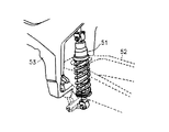
一般に二輪車等におけるダンパは、油圧式のものが知られており、たとえば、図3に示すように、二輪車のフレームとスイングアームとの間に介装されている。
【0003】
そして、このようなダンパは、車両走行中に、スイングアームの先端側に回動自在に装着された車輪(図示せず)を介して入力される路面からの衝撃や振動を減衰して自動二輪車の乗り心地を向上させる。
【0004】
また、図4に示すように近年油を必要としない新しい電磁力を利用したダンパの提案がされるに至っている(たとえば、特許文献1参照)。
【0005】
この電磁力を利用したダンパは、モータのシャフトにサスペンションアームの基端側を結合し、その先端側には車輪が回動自在に取付けられ、さらに、モータは制御装置に電気的に接続されている。
【0006】
そして、この電磁力を利用したダンパにおいては、サスペンションアームが回動運動を呈すると、制御装置からモータに対し電流を供給して、モータに電磁力を発生させ、この電磁力に起因するスイングアームの回動方向に抗するトルクを減衰力として利用しようとするものである。
【0007】
【特許文献1】
特開平7−149130号公報(段落番号0013から0017、図1)
【0008】
【発明が解決しようとする課題】
しかしながら、上記の油を利用したダンパでは、機能面で特に問題はあるわけではなく、高減衰力が得られ、上記振動の抑制に便利であるが、その反面、油が必要であり、この油の漏れを防止するシール機構や複雑なバルブ機構、制御機構を必要とする。
【0009】
また、万が一、油が漏れた場合には、地球環境の悪化の原因になると指摘される恐れがある。オイルダンパに使用する作動油を、地球環境を汚染しない生分解性作動油とすることが提言されているが、生分解性作動油は極めて高価であり、またこの種の作動油の特性は緩衝器の適正な減衰力を発生させるのに不十分であるので、実用化されていない。
【0010】
さらに、上記した電磁力を利用したダンパは、上述のように電流供給が必要であるので、特に電源を有しない二輪車や、取付けスペースや重量の問題等からバッテリの容量に制約を受ける自動二輪車に適用するには困難な場合がある。
【0011】
そこで、本発明の目的は、特に作動油を必要とせず、かつ、電流供給を必要としないか、省電力のロータリダンパを提供することを目的とする。
【0012】
前記の目的を達成するために本発明の第1の課題解決手段におけるロータリダンパは、二輪車のスイングアームおよび二輪車の車体フレームの一方に結合した中空パイプ内に回動自在に挿通され、かつ、二輪車のスイングアームおよび二輪車の車体フレームの他方に結合したシャフトと、シャフトに固着したコイルと、上記中空パイプの内周に上記コイルと対向し、かつ、中空パイプ内に磁界を発生させるように固着した永久磁石とを有してなり、コイルの両端を短絡もしくは制御装置に接続させたことを特徴とする。
【0013】
上記の構成により、二輪車のスイングアームが車体フレームに対し回動運動すると、中空パイプが回動し、中空パイプに固着した永久磁石も回動運動を呈することになるので、シャフトに形成したコイルが、中空パイプ内周に固着した永久磁石の磁束を横切ることとなり、コイルに誘導起電力が発生する。
【0014】
そして、上述の通りコイルの両端が短絡されている場合には、コイルには中空パイプの回動に抗するトルクを発生するように電流が流れるので、中空パイプの回動に抗するトルクが中空パイプの回動運動を抑制することとなる。
【0015】
すなわち、中空パイプの回動に抗するトルクが減衰力として作用することとなるので、作動油を必要とせず、電流供給も行わずに減衰力の発生が可能である。さらに、作動油を必要とするダンパに比較してダンパを軽量なものとすることができるとともに、小型化できるので二輪車への搭載性も向上する。
【0016】
また、コイルの両端を制御装置に接続する場合には、誘導起電力に起因するコイルに流れる電流の大きさを制御装置によりコントロールすることが可能となるので、中空パイプの回動に抗するトルクの調節が可能となる。このとき、コイルに電流供給しなくとも良いので、電力供給は制御装置にのみ行えばよいので、省電力で所望の減衰力を発生することができる。
【0017】
さらに、二輪車の走行状態、すなわち、車速やハンドル操舵角速度等の情報を基にした減衰力制御が可能となる。
【0018】
したがって、このロータリダンパを二輪車に適用して乗り心地を向上することができる。
【0019】
また、本発明の第2の課題解決手段におけるロータリダンパは、二輪車のスイングアームおよび二輪車の車体フレームの一方に結合した中空パイプ内に回動自在に挿通され、かつ、二輪車のスイングアームおよび二輪車の車体フレームの他方に結合したシャフトと、シャフトに中空パイプ内に磁界を発生させるように固着した永久磁石と、中空パイプの内周に上記永久磁石と対向するように固着したコイルとを有してなり、コイルの両端を短絡もしくは制御装置に接続させたことを特徴とする。
【0020】
したがって、この場合も第1の課題解決手段と同様に、中空パイプの回動により、コイルには中空パイプの回動に抗するトルクを発生するように電流が流れるので、中空パイプの回動に抗するトルクが中空パイプの回動運動を抑制することとなるので、第1の課題解決手段と同様の作用効果を奏することが可能である。
【0021】
そして、本発明の第3の課題解決手段におけるロータリダンパは、二輪車のスイングアームおよび二輪車の車体フレームの一方に結合した中空パイプ内に回動自在に挿通され、かつ、二輪車のスイングアームおよび二輪車の車体フレームの他方に結合したシャフトと、上記中空パイプとシャフトの間に回動自在に挿通した筒体と、シャフトに設けた径方向に伸びる一本または複数本のアームと、各アームの先端に設けた遊星歯車と、筒体に設けた第1太陽歯車と、同じく筒体に固着したコイルと、中空パイプ内に設けた第2太陽歯車と、中空パイプの内周に上記コイルと対向し、かつ、中空パイプ内に磁界を発生させるように固着した永久磁石とを有してなり、第1太陽歯車と第2太陽歯車との間に遊星歯車を介装して、各歯車を噛合させ、コイルの両端を短絡もしくは制御装置に接続させたことを特徴とする。
【0022】
この場合には、シャフトが回動すると、シャフトのアームに設けられた遊星歯車も回動し、これに噛合する第1太陽歯車も回動するから、筒体に取付けられたコイルも回動し、このコイルが、中空パイプの内周に固着した永久磁石の磁束を横切るので、第1の課題解決手段同様、減衰力を発生することが可能である。
【0023】
したがって、その作用効果も第1の課題解決手段と同様であるが、上述のように、第1、第2太陽歯車および遊星歯車でプラネタリギアを構成し、このプラネタリギアを介しているから、筒体の回動速度を中空パイプの回動速度より増速もしくは減速させることが可能となり、各歯車のギア比を適切な組み合わせとすることで、所望の減衰力を得ることが出来る。
【0024】
すなわち、実際にこのロータリダンパを二輪車に適用する際に、適用車種に応じた必要な減衰力は、各歯車のギア比を適切なものとすれば、コイルや永久磁石の規格を車種に応じて変更することなしに得られる。
【0025】
また、ギア比によって、減衰力を変化させることができるので、大きな減衰力が必要な場合でも、コイルや永久磁石を大型化する必要が無くなる。
【0026】
さらに、本発明の第4の課題解決手段におけるロータリダンパは、二輪車のスイングアームおよび二輪車の車体フレームの一方に結合した中空パイプ内に回動自在に挿通され、かつ、二輪車のスイングアームおよび二輪車の車体フレームの他方に結合したシャフトと、上記中空パイプとシャフトの間に回動自在に挿通した筒体と、シャフトに設けた径方向に伸びる一本または複数本のアームと、各アームの先端に設けた遊星歯車と、筒体に設けた第1太陽歯車と、同じく筒体に中空パイプ内に磁界を発生させるように固着した永久磁石と、中空パイプ内に設けた第2太陽歯車と、中空パイプの内周に上記永久磁石と対向するように固着したコイルとを有してなり、第1太陽歯車と第2太陽歯車との間に遊星歯車を介装して、各歯車を噛合させ、コイルの両端を短絡もしくは制御装置に接続させたことを特徴とする。
【0027】
そして、さらに、本発明の第5の課題解決手段におけるロータリダンパは、二輪車のスイングアームおよび二輪車の車体フレームの一方に結合した中空パイプ内に回動自在に挿通され、かつ、二輪車のスイングアームおよび二輪車の車体フレームの他方に結合したシャフトと、上記中空パイプとシャフトの間に回動自在に挿通した筒体と、シャフトに設けた径方向に伸びる一本または複数本のアームと、各アームの先端に設けた遊星歯車と、筒体に設けた第1太陽歯車と、同じく筒体に固着したコイルと、中空パイプ内に設けた第2太陽歯車と、シャフトに上記コイルと対向し、かつ、中空パイプ内に磁界を発生させるように固着した永久磁石とを有してなり、第1太陽歯車と第2太陽歯車との間に遊星歯車を介装して、各歯車を噛合させ、コイルの両端を短絡もしくは制御装置に接続させたことを特徴とする。
【0028】
そして、また、本発明の第6の課題解決手段におけるロータリダンパは、二輪車のスイングアームおよび二輪車の車体フレームの一方に結合した中空パイプ内に回動自在に挿通され、かつ、二輪車のスイングアームおよび二輪車の車体フレームの他方に結合したシャフトと、上記中空パイプとシャフトの間に回動自在に挿通した筒体と、シャフトに設けた径方向に伸びる一本または複数本のアームと、各アームの先端に設けた遊星歯車と、筒体に設けた第1太陽歯車と、同じく筒体に中空パイプ内に磁界を発生させるように固着した永久磁石と、中空パイプ内に設けた第2太陽歯車と、シャフトに上記永久磁石と対向するように固着したコイルとを有してなり、第1太陽歯車と第2太陽歯車との間に遊星歯車を介装して、各歯車を噛合させ、コイルの両端を短絡もしくは制御装置に接続させたことを特徴とする。
【0029】
したがって、第4、第5、第6の課題解決手段によっても、プラネタリギアを介しているから、筒体の回動速度を中空パイプの回動速度より増速もしくは減速させることが可能であるので、これらの課題解決手段でも第3の課題解決手段と同様の作用効果を奏することが可能である。
【0034】
また、さらに、本発明の第7の課題解決手段におけるロータリダンパは、第1から第6のいずれかの課題解決手段において、制御装置が、車両速度、操舵角速度、後輪分担荷重の各値のうち、いずれか1つまたは任意に組み合わせた各値に基づき、上記コイルに流れる電流を調節することを特徴とする。
【0035】
したがって、制御装置が、車両速度、操舵角速度、後輪分担荷重の各値のうち、いずれか1つまたは任意に組み合わせた各値に基づいて、中空パイプの回動による誘導起電力に基づきコイルに流れる電流量を調整することが可能となる。
【0036】
また、このとき、コイルには誘導起電力に基づく電流が流れるので、特に、通電する必要が無く、電力供給を制御装置のみに行えばよいので、消費電力を低く押えることが可能となるとともに、電流量を適切なものとすることにより、ロータリダンパの発生する減衰力も自動二輪車等の走行状態に適したものとすることに調節可能であるので、乗り心地が向上する。
【0037】
【発明の実施の形態】
以下、この発明が自動二輪車に具現化された場合について説明するが、この発明の意図するところは、このロータリダンパを、二輪車の車体フレームと車体フレームに対して回動運動するスイングアームとの間に介装して、その回動運動を減衰させようとするものである。
【0038】
本発明にかかるロータリダンパの第1の実施の形態は、図1に示すように、二輪車のスイングアームSに結合した中空パイプ2と、中空パイプ2内に回動自在に挿通され、かつ、二輪車の車体フレームFに結合したシャフト1と、シャフト1に固着したコイル3と、中空パイプ2の内周に上記コイル3と対向し、かつ、中空パイプ2内に磁界を発生させるように固着した永久磁石5a、5bとで構成されている。
【0039】
以下、更に詳細な構造について説明する。中空パイプ2は筒状に形成され、外周側面がスイングアームSの基端側に結合されるとともに、その内周には、永久磁石5a、5bを取付けたヨーク4が固着されており、この永久磁石5a、5bで中空パイプ2内に磁界を発生させている。また、ヨーク4には、後述の整流子6に接触してコイル3に流れる電流を整流するブラシ7と、ブラシ7を保持するブラシホルダ9と、ブラシ7に接続された電線8が設けられている。
【0040】
なお、ブラシ7が一つしか図示されていないが、ブラシ7は一対となるように設けられ、各ブラシ7が、整流子6に接触するようになっている。そして、電線8は、図示はしないが各ブラシ7に接続する2本の導線から構成されており、その先端で短絡されている。したがって、この場合には電線8を中空パイプ2外で短絡させる必要は無いので、各ブラシ7同士を中空パイプ2内で短絡させても良い。
【0041】
さらに、スイングアームSは、上述のように基端側が中空パイプ2に結合されているが、その先端側には車輪Wが回動自在に取付けられている。
【0042】
シャフト1の外周には、コア(付示せず)に導線を巻きつけたコイル3が形成されるとともに、コイル3の両端部を同じくシャフト1の外周であって、コイル3の近傍に設けた整流子6に接続されている。
【0043】
そして、このシャフト1は、中空パイプ2の内周の両端部に設けた軸受13、19を介して中空パイプ2内に回動自在に挿入され、このとき、シャフト1に設けたコイル3は、上述の永久磁石5a、5bと対向するように配置されている。
【0044】
また、シャフト1の一端部は、二つのブラケット14、16で車体フレームFを挟持することにより結合されており、同様にその他端部も二つのブラケット15、17で車体フレームFを挟持することにより結合されている。このような構成とすることにより、中空パイプ2に結合されたスイングアームSはシャフト1を軸として、車体Fフレームに対し回動運動することが可能である。
【0045】
なお、本実施の形態においては、中空パイプ2をスイングアームSに結合し、シャフト1を車体フレームFに結合しているが、逆に中空パイプ2を車体フレームFに結合し、シャフト1をスイングアームSに結合しても良く、このことは他の実施の形態においても同様である。
【0046】
さて、このロータリダンパの作用であるが、二輪車の走行中、スイングアームSに、その先端に取付けられた車輪Wを介して路面から振動や衝撃等が入力されると、スイングアームSが回動運動を呈する。すると、スイングアームSに結合された中空パイプ2も回動し、中空パイプ2に固着した永久磁石5a、5bも回動するが、このとき、不動のシャフト1に形成したコイル3が、永久磁石5a、5bが中空パイプ2内に形成している磁束を横切ることとなり、コイル3には誘導起電力が発生する。
そして、コイル3には、上記誘導起電力に起因する電流が流れるが、コイル3の両端は整流子6およびブラシ7および電線8の導線を介して短絡されているので、コイル3は中空パイプ2の回動に抗するトルクを発生し、この中空パイプ2の回動に抗するトルクが中空パイプ2の回動運動を抑制することとなる。したがって、中空パイプ2の回動運動が抑制されるので、中空パイプ2に結合されたスイングアームSの回動運動が抑制されることとなる。
【0047】
すなわち、中空パイプ2の回動に抗するトルクが減衰力として作用することとなるので、特段の電源や作動油を使用せずに、誘導起電力によりコイルに流れる電流を利用して減衰力の発生が可能であり、この減衰力により自動二輪車の走行時には、スイングアームSに振動や衝撃が入力されても、その振動や衝撃を抑制でき、自動二輪車等の乗り心地が向上する。さらに、作動油を必要とするダンパに比較してダンパを軽量なものとすることができるとともに、小型化できるので二輪車等への搭載性も向上する。
【0048】
また、上記したところでは、コイル3を短絡して中空パイプ2の回動に抗するトルクを得ているが、これに換えて、たとえば、コイル3を誘導機電力の大きさによって内部抵抗を変更可能な電気回路に接続し、誘導起電力に起因するコイル3に流れる電流量を、この電気回路によって調節しても良い。そうすることによって、コイル3に流れる電流量を調節することが可能となり、すると、ロータリダンパの発生する減衰力も調節可能となる。
【0049】
なお、図示したところでは、シャフト1にコイル3を巻装し、中空パイプ2の内周に永久磁石5a、5bを設けているが、逆にシャフト1に永久磁石を取付け、中空パイプ2側にコイルを取付けても良い。この場合には、中空パイプ2が回動すると、コイルが回動し、コイルが磁束を横切ることになるので、やはりコイルには誘導起電力が発生し、電流が流れ、中空パイプの回動に抗するトルクが発生するので、上述のように、減衰作用を呈することとなる。
【0050】
つづいて、本実施の形態の変形例について説明する。当該変形例にあっては、その基本構成は上述の実施の形態と同様にして、そのロータリダンパの電線8を制御装置(図示せず)に接続したものである。
【0051】
制御装置は、たとえば、自動二輪車の速度を検出する車速検出器と、車両の操舵角速度を検出する操舵角速度検出器と、車両の後輪分担荷重を検出する後輪分担荷重検出器と、前記車速と操舵角速度の検出結果に基づき減衰力を演算するコントローラと、前記コントローラの演算結果に基づき上記コイルに流れる電流量を調節する電流調節手段とで構成される。
【0052】
以下、詳細に説明すると、コントローラは、車速検出器と操舵角速度検出器と後輪分担荷重検出器とに接続され、上記各検出器が検出した検出結果を受け取り可能となっている。
【0053】
ここで、コントローラは、ハードウェアとしては、図示しないが、各検出器が検出した車速および操舵角速度の信号を受け取り、前記各信号に基づいて制御力を演算でき、制御信号としての電力を出力できるものであれば良く、例えば、前記信号増幅するためのアンプと、アナログ信号をデジタル信号に変換する変換器と低周波及び高周波成分をカットするバンドパスフィルタと、CPU、ROM、RAM、水晶発振子及びこれらを連絡するバスラインからなるコンピュータシステムとにより構成され、ロータリダンパの必要減衰力の演算に使用される演算処理手順と制御信号出力手順は、プログラムとしてROMに予め格納させておくとする周知なシステムで良い。
【0054】
さらに、コントローラは、電流調節手段に接続されている。電流調節手段は、コントローラからの信号を受け取り、誘導起電力によってコイル3に流れる電流量を調節できるものであれば良く、したがって、たとえば、電流調節手段は、コントローラからの信号により駆動するアクチュエータと、コイル3と接続される電気回路内にポテンショメータを配設したものとして、アクチュエータによりポテンショメータを駆動して、当該電気回路の抵抗を変化させ、誘導起電力によってコイル3に流れる電流量を調節するものとしても良いし、他に駆動源を用いずに電気的に電流調節手段の回路の抵抗を変化させても良い。
【0055】
また、速度検出器は加速度検出器を使用して、コントローラで検出結果を積分して自動二輪車の速度を演算してもよい。
【0056】
つづいて、本実施の形態におけるロータリダンパの動作について説明する。車両走行中に、先ず、車速検出器と操舵角速度検出器と後輪分担荷重検出器が、車速および操舵角速度および後輪分担荷重の各値を検出し、コントローラに前記車速および操舵角速度および後輪分担荷重が信号として入力される。
【0057】
つぎに、コントローラは、入力された車速および操舵角速度および後輪分担荷重の各値に基づいて、ロータリダンパの適切な減衰力を演算する。
【0058】
そして、この演算結果に基づき電流調整手段が、誘導起電力によりコイル3に流れる電流量を変化させて、コイル3に生じる誘導起電力に起因する中空パイプ2の回動運動に抗するトルク、すなわち減衰力を変化させる。
【0059】
この状態で、中空パイプ2が回動すると、上述のようにコイル3に誘導起電力が発生し電流が流れるが、電流量は先程の電流調整手段によって調節されているので、ロータリダンパはコントローラが演算した減衰力を発生することとなる。すなわち、本実施の形態における制御手段によって、ロータリダンパの発生する減衰力を自動二輪車等の走行状態に適したものとすることに調節可能であるので、乗り心地が向上する。
【0060】
このとき、たとえば、上述のように電流調節手段が、アクチュエータと、ポテンショメータとで構成される場合には、アクチュエータがポテンショメータを駆動し電流調節手段の電気回路の抵抗値を変化させるが、あらかじめ、電流調節手段を、ロータリダンパに必要な減衰力を発生させるのに必要とされる抵抗値を選択できるように調整しておけば良い。
【0061】
また、コイルには誘導起電力に基づく電流が流れるので、特に、通電する必要が無く、電力供給を制御装置のみに行えばよいので、消費電力を低く押えることが可能となる。
【0062】
ここで、本実施の形態では、上述のように誘導起電力に起因してコイル3に流れる電流量を調節することとなるので、コントローラにロータリダンパの減衰力を演算させるのではなく、ロータリダンパが減衰力を発現させるのに、必要な抵抗値を演算させるようにしてもよい。
【0063】
また、コントローラにあらかじめ記録される、車速および操舵角速度に基づくロータリダンパに発生させる減衰力を演算する演算手法についてであるが、このロータリダンパが搭載される自動二輪車等の運動性能や車重等により、適宜その自動二輪車等に適した制御を行えるように設定すればよい。たとえば、コントローラが自動二輪車の速度が高速で操舵角速度が高い場合には、ロータリダンパの発現する減衰力を高めような制御を行えるように設定されたり、自動二輪車が加速中で後輪分担荷重が大きい場合には接地性を向上すべく減衰力を高めるように設定されたりするであろう。
【0064】
なお、上記したところでは、車速、操舵角速度、後輪分担荷重の各値に基づいてコイルに流れる電流を調節しているが、上記した3つの各値のうち、いずれか1つまたは任意に組み合わせた各値に基づいてコイルに流れる電流を調節することも可能である。
【0065】
つづいて、第2の実施の形態について説明する。ここで、第1の実施の形態のロータリダンパと同一の部材については、説明が重複するので、同一の符号を付するのみとして、その詳細については説明を省略する。
【0066】
第2の実施の形態のロータリダンパは、図2に示すように、二輪車のスイングアームSに結合した中空パイプ25と、中空パイプ25内に回動自在に挿通され、かつ、二輪車の車体フレームFに結合したシャフト20と、上記中空パイプ25とシャフト20の間に回動自在に挿通した筒体27と、シャフト20に設けた径方向に伸びる2本のアーム21と、各アーム21の先端に設けた遊星歯車28と、筒体27に設けた第1太陽歯車27aと、同じく筒体27に固着したコイル3と、中空パイプ25内に設けた第2太陽歯車26と、中空パイプ25の内周に上記コイル3と対向し、かつ、中空パイプ25内に磁界を発生させるように固着した永久磁石5a、5bとで構成されている。
【0067】
以下、詳細に説明すると、中空パイプ25は、第1の実施の形態同様に筒状に形成され、外周側面がスイングアームSに結合されるとともに、その内周には、永久磁石5a、5bを取付けたヨーク4が固着されており、この永久磁石5a、5bで中空パイプ25内に磁界を発生させている。また、ヨーク4には、後述の整流子6に接触してコイルに流れる電流を整流するブラシ7と、ブラシ7を保持するブラシホルダ9と、ブラシ7に接続された電線8が設けられている。第2の実施の形態では、これらの構成に加えて、中空パイプ25の内周に第2太陽歯車26を設けている。なお、ブラシ7が一つしか図示されていないが、ブラシ7は一対となるように設けられ、各ブラシ7が、整流子6に接触するようになっている。そして、電線8は、図示はしないが各ブラシ7に接続する2本の導線から構成されており、その先端で短絡されている。したがって、この場合には電線8を中空パイプ25外で短絡させる必要は無いので、各ブラシ7同士を中空パイプ2内で短絡させても良いのは、第1の実施の形態と同様である。
【0068】
そして、シャフト20と中空パイプ25の間に筒体27を挿通し、この筒体27は中空パイプ2に固着されたヨーク4の両端部に配在の軸受29、30を介して、中空パイプ25およびシャフト20に対して回動可能となっている。また、第1の実施の形態では、シャフトにコイルを巻装したが、第2の実施の形態では、この筒体27の外周にコア(付示せず)に導線を巻きつけたコイル3が形成されるとともに、コイル3の両端部を同じく筒体27の外周であって、コイル3の近傍に設けた整流子6に接続されており、コイル3は、上述の永久磁石5a、5bと対向するように配置されている。さらに、この筒体27の一端部には第1太陽歯車27aが形成されている。
【0069】
他方、シャフト20には2本のアーム21を設けて、その各アーム21の先端に遊星歯車28を設けてあり、各遊星歯車28を筒体27に形成した第1太陽歯車27aと中空パイプ25の内周に設けた第2太陽歯車26との間に介装して、各歯車が互いに噛合するようになっている。すなわち、これら歯車でプラネタリギアを構成している。
【0070】
また、シャフト20の一端部は、二つのブラケット14、16で車体フレームFを挟持することにより結合されており、同様にその他端部も二つのブラケット15、17で車体フレームFを挟持することにより結合されている。このような構成とすることにより、中空パイプ25に結合されたスイングアームSはシャフト1を軸として、車体Fフレームに対し回動運動することが可能である。
【0071】
さて、このロータリダンパの作用であるが、自動二輪車の走行中にスイングアームSが路面から振動や衝撃により回動運動を呈すると、中空パイプ25に設けた第2太陽歯車26も回動し、シャフト20が不動であるので、シャフト20に設けた遊星歯車28が回動する。すると、シャフト20の各アーム21に設けた遊星歯車28がその場で回動するので、その回動運動が第1太陽歯車27aに伝達される。
【0072】
すると、筒体27の外周に形成したコイル3も回動するが、このとき、コイル3が永久磁石5a、5bが中空パイプ2内に形成している磁束を横切ることとなり、コイル3には誘導起電力が誘導起電力を発生する。
そして、コイル3には、上記誘導起電力に起因する電流が流れるが、コイル3の両端は整流子6およびブラシ7および電線8の導線を介して短絡されているので、コイル3は中空パイプ25の回動に抗するトルクを発生し、この中空パイプ2の回動に抗するトルクが中空パイプ25の回動運動を抑制することとなる。
【0073】
すなわち、中空パイプ25の回動に抗するトルクが減衰力として作用することとなるので、特段の電源や作動油を使用せずに、誘導起電力によりコイルに流れる電流を利用して減衰力の発生が可能であり、この減衰力により自動二輪車の走行時には、スイングアームSに振動や衝撃が入力されても、その振動や衝撃を抑制でき、自動二輪車等の乗り心地が向上する。さらに、作動油を必要とするダンパに比較してダンパを軽量なものとすることができるとともに、小型化できるので二輪車等への搭載性も向上する。したがって、第1の実施の形態と同様の作用効果を奏することができる。
【0074】
ここで、上記プラネタリギアを介しているから、筒体27の回動速度を中空パイプ2の回動速度より増速もしくは減速させることが可能となり、各歯車のギア比を適切な組み合わせとすることで、所望の減衰力を得ることが出来る。
【0075】
すなわち、実際にこのロータリダンパを自動二輪車等に適用する際に、適用車種に応じた必要な減衰力は、各歯車のギア比を適切なものとすれば、コイルや永久磁石の規格を車種に応じて変更することなしに得られる。
【0076】
また、ギア比によって、減衰力を変化させることができるので、大きな減衰力が必要な場合でも、コイルや永久磁石を大型化する必要が無くなる。
【0077】
また、上記したところでは、コイル3を短絡して中空パイプ25の回動に抗するトルクを得ているが、これに換えて、たとえば、コイル3を誘導起電力の大きさによって内部抵抗を変更可能な電気回路に接続し、誘導起電力に起因するコイル3に流れる電流量を、この電気回路によって調節してもよいことは、第1の実施の形態と同様であり、そうすることによって、コイル3に流れる電流量を調節することが可能となり、すると、ロータリダンパの発生する減衰力も調節可能となる。
【0078】
なお、図示したところでは、筒体27にコイル3を形成し、中空パイプ25の内周に永久磁石5a、5bを設けているが、逆に筒体27に永久磁石を取付け、中空パイプ25側にコイルを取付けても良い。さらに、シャフト20にコイルを形成し、筒体27に永久磁石を取付けるか、または、シャフト20に永久磁石を取付け、筒体27にコイルを形成してもよい。この場合には、シャフトが回動すると、永久磁石またはコイルが回動し、コイルが磁束を横切ることになるので、やはりコイルには誘導起電力が発生し、電流が流れ、中空パイプの回動に抗するトルクが発生するので、上述のように、減衰作用を呈することとなる。
【0079】
なお、コイル3を第1の実施の形態で説明した制御装置に接続すれば、ロータリダンパが発生する減衰力を制御できるのは第1の実施の形態の変形例と同様である。
【0092】
【発明の効果】
以上のように、請求項1、2、3、4、5、6に記載の発明によれば、中空パイプが回動すると、中空パイプに固着したコイルまたは永久磁石も回動運動を呈することになるので、コイルが、中空パイプまたはシャフトに固着した永久磁石の磁束を横切ることとなり、コイルに誘導起電力が発生するので、中空パイプの回動に抗するトルクが発生し、中空パイプの回動運動を抑制できる。
【0093】
すなわち、中空パイプの回動に抗するトルクが減衰力として作用することとなるので、作動油を必要とせず、電流供給も行わずに減衰力の発生が可能である。さらに、作動油を必要とするダンパに比較してダンパを軽量なものとすることができるとともに、小型化できるので二輪車への搭載性も向上する。
【0094】
また、コイルの両端を制御装置に接続する場合には、誘導起電力に起因するコイルに流れる電流の大きさを制御装置によりコントロールすることが可能となるので、中空パイプの回動に抗するトルクの調節が可能となる。このとき、コイルに電流供給しなくとも良いので、電力供給は制御装置にのみ行えばよいので、省電力で所望の減衰力を発生することができる。
【0095】
さらに、二輪車等の走行状態、すなわち、車速やハンドル操舵角速度等の情報を基にした減衰力制御が可能となる。
【0096】
したがって、このロータリダンパを二輪車に適用して乗り心地を向上することができる。
【0097】
また、請求項3、4、5および6に記載の発明によれば、プラネタリギアを介しているから、筒体の回動速度を中空パイプの回動速度より増速もしくは減速させることが可能となり、各歯車のギア比を適切な組み合わせとすることで、所望の減衰力を得ることが出来る。
【0098】
すなわち、実際にこのロータリダンパを自動二輪車等に適用する際に、適用車種に応じた必要な減衰力は、各歯車のギア比を適切なものとすれば、コイルや永久磁石の規格を車種に応じて変更することなしに得られる。
【0099】
また、ギア比によって、減衰力を変化させることができるので、大きな減衰力が必要な場合でも、コイルや永久磁石を大型化する必要が無くなる。
【0103】
また、請求項7に記載の発明によれば、制御装置が、車両速度、操舵角速度、後輪分担荷重の各値のうち、いずれか1つまたは任意に組み合わせた各値に基づいて、中空パイプの回動による誘導起電力に基づきコイルに流れる電流量を調整することが可能となる。
【0104】
また、このとき、コイルには誘導起電力に基づく電流が流れるので、特に、通電する必要が無く、電力供給を制御装置のみに行えばよいので、消費電力を低く押えることが可能となるとともに、電流量を適切なものとすることにより、ロータリダンパの発生する減衰力も自動二輪車等の走行状態に適したものとすることに調節可能であるので、乗り心地が向上する。
【図面の簡単な説明】
【図1】 第1の実施の形態におけるロータリダンパの側面断面図である。
【図2】 第2の実施の形態におけるロータリダンパの側面断面図である。
【図3】 油圧式ダンパの斜視図である。
【図4】 電磁力を利用したダンパの概念図である。
【符号の説明】
1、20 シャフト
2 中空パイプ
3 コイル
4 ヨーク
5a、5b 永久磁石
6 整流子
7 ブラシ
8 電線
9 ブラシホルダ
21 アーム
26 第2太陽歯車
27 筒体
27a 第1太陽歯車
28 遊星歯車
36 歯車部
37 モータ側歯車
38 モータシャフト
F 第2部材たる車体フレーム
M モータ
S 第1部材たるスイングアーム[0001]
BACKGROUND OF THE INVENTION
The present invention relates to a rotary damper, and more particularly to a rotary damper suitable for a motorcycle using an electromagnetic force as a damping force.
[0002]
[Prior art]
In general, hydraulic dampers are known for motorcycles, for example,FIG.As shown in FIG. 2, the motorcycle is interposed between a frame and a swing arm.
[0003]
Such a damper attenuates an impact or vibration from a road surface that is input via a wheel (not shown) that is rotatably mounted on the front end side of the swing arm while the vehicle is running. Improve the ride comfort.
[0004]
Also,FIG.In recent years, a damper using a new electromagnetic force that does not require oil has been proposed (see, for example, Patent Document 1).
[0005]
The damper using this electromagnetic force has a base end side of a suspension arm coupled to a shaft of a motor, a wheel is rotatably attached to the tip end side, and the motor is electrically connected to a control device. Yes.
[0006]
In the damper using the electromagnetic force, when the suspension arm exhibits a rotational movement, a current is supplied from the control device to the motor to generate the electromagnetic force in the motor, and the swing arm caused by the electromagnetic force is generated. The torque that resists the direction of rotation is to be used as the damping force.
[0007]
[Patent Document 1]
JP 7-149130 A (paragraph numbers 0013 to 0017, FIG. 1)
[0008]
[Problems to be solved by the invention]
However, in the damper using the above oil, there is no particular problem in terms of function, and a high damping force is obtained and it is convenient for suppressing the vibration. However, on the other hand, oil is necessary. It requires a seal mechanism, a complicated valve mechanism, and a control mechanism to prevent leakage of the air.
[0009]
In the unlikely event that oil leaks, it may be pointed out that it may cause deterioration of the global environment. Although it has been suggested that the hydraulic fluid used in the oil damper be a biodegradable hydraulic fluid that does not pollute the global environment, the biodegradable hydraulic fluid is extremely expensive and the characteristics of this type of hydraulic fluid are buffered. Since it is insufficient to generate the proper damping force of the vessel, it has not been put into practical use.
[0010]
Furthermore, since the damper using the electromagnetic force described above requires current supply as described above, it is particularly suitable for motorcycles that do not have a power source, and motorcycles that are restricted by battery capacity due to problems such as mounting space and weight. It can be difficult to apply.
[0011]
Accordingly, an object of the present invention is to provide a rotary damper that does not particularly require hydraulic oil and that does not require current supply or that saves power.
[0012]
In order to achieve the above object, the rotary damper in the first problem solving means of the present invention comprises:One of the swing arm of the motorcycle and the body frame of the motorcycleIt is inserted through the coupled hollow pipe so that it can rotate freely, andOn the other side of the swing arm of the motorcycle and the body frame of the motorcycleA coupled shaft, a coil fixed to the shaft, a permanent magnet facing the coil on the inner periphery of the hollow pipe and fixed to generate a magnetic field in the hollow pipe. Both ends are short-circuited or connected to a control device.
[0013]
With the above configuration,The swing arm of a motorcycle is the body frame, The hollow pipe rotates, and the permanent magnet fixed to the hollow pipe also exhibits a rotational movement. Therefore, the coil formed on the shaft has the magnetic flux of the permanent magnet fixed to the inner periphery of the hollow pipe. And an induced electromotive force is generated in the coil.
[0014]
When both ends of the coil are short-circuited as described above, a current flows through the coil so as to generate a torque against the rotation of the hollow pipe, so that the torque against the rotation of the hollow pipe is hollow. The rotational movement of the pipe will be suppressed.
[0015]
That is, since the torque against the rotation of the hollow pipe acts as a damping force, no hydraulic oil is required and the damping force can be generated without supplying current. In addition, the damper can be made lighter and smaller than the damper that requires hydraulic oil.To motorcyclesMountability is also improved.
[0016]
In addition, when both ends of the coil are connected to the control device, it is possible to control the magnitude of the current flowing through the coil due to the induced electromotive force by the control device, so that the torque resists the rotation of the hollow pipe. Can be adjusted. At this time, since it is not necessary to supply current to the coil, it is only necessary to supply power to the control device.
[0017]
further,MotorcycleDamping force control based on information on the running state, that is, vehicle speed, steering wheel steering angular velocity, and the like is possible.
[0018]
Therefore, this rotary damperApply to motorcycleRiding comfort can be improved.
[0019]
The rotary damper in the second problem solving means of the present invention is:One of the swing arm of the motorcycle and the body frame of the motorcycleIt is inserted through the coupled hollow pipe so that it can rotate freely, andOn the other side of the swing arm of the motorcycle and the body frame of the motorcycleAnd a permanent magnet fixed to the shaft so as to generate a magnetic field in the hollow pipe, and a coil fixed to the inner periphery of the hollow pipe so as to face the permanent magnet. Is short-circuited or connected to a control device.
[0020]
Therefore, in this case as well, as in the first problem solving means, the rotation of the hollow pipe generates torque that resists the rotation of the hollow pipe.So that the current isSince it flows, the torque against the rotation of the hollow pipe suppresses the rotation movement of the hollow pipe, so that it is possible to achieve the same effect as the first problem solving means.
[0021]
The rotary damper in the third problem solving means of the present invention is:One of the swing arm of the motorcycle and the body frame of the motorcycleIt is inserted through the coupled hollow pipe so that it can rotate freely, andOn the other side of the swing arm of the motorcycle and the body frame of the motorcycleA coupled shaft, a cylindrical body rotatably inserted between the hollow pipe and the shaft, one or more arms extending in the radial direction provided on the shaft, and a planetary gear provided on the tip of each arm; The first sun gear provided in the cylinder, the coil fixed to the cylinder, the second sun gear provided in the hollow pipe, the coil on the inner periphery of the hollow pipe, and in the hollow pipe And a permanent magnet fixed so as to generate a magnetic field, and a planetary gear is interposed between the first sun gear and the second sun gear so that each gear is meshed and both ends of the coil are short-circuited. Alternatively, it is connected to a control device.
[0022]
In this case, when the shaft rotates, the planetary gear provided on the arm of the shaft also rotates, and the first sun gear meshing with the planetary gear also rotates, so the coil attached to the cylinder also rotates. Since this coil crosses the magnetic flux of the permanent magnet fixed to the inner periphery of the hollow pipe, it is possible to generate a damping force as in the first problem solving means.
[0023]
Therefore, the operational effect is the same as that of the first problem solving means. However, as described above, the planetary gear is constituted by the first and second sun gears and the planetary gear, and this planetary gear is interposed. The rotational speed of the body can be increased or decreased from the rotational speed of the hollow pipe, and a desired damping force can be obtained by appropriately combining the gear ratios of the gears.
[0024]
In other words, this rotary damper is actuallyApplies to motorcyclesIn this case, the necessary damping force according to the applicable vehicle type can be obtained without changing the standard of the coil or permanent magnet according to the vehicle type if the gear ratio of each gear is appropriate.
[0025]
Further, since the damping force can be changed depending on the gear ratio, it is not necessary to increase the size of the coil or the permanent magnet even when a large damping force is required.
[0026]
Furthermore, the rotary damper in the fourth problem solving means of the present invention is:One of the swing arm of the motorcycle and the body frame of the motorcycleIt is inserted through the coupled hollow pipe so that it can rotate freely, andOn the other side of the swing arm of the motorcycle and the body frame of the motorcycleA coupled shaft, a cylindrical body rotatably inserted between the hollow pipe and the shaft, one or more arms extending in the radial direction provided on the shaft, and a planetary gear provided on the tip of each arm; A first sun gear provided in the cylinder, a permanent magnet fixed to the cylinder so as to generate a magnetic field in the hollow pipe, a second sun gear provided in the hollow pipe, and an inner periphery of the hollow pipe A coil fixed so as to face the permanent magnet, a planetary gear is interposed between the first sun gear and the second sun gear, the gears are meshed, and both ends of the coil are short-circuited. Alternatively, it is connected to a control device.
[0027]
Further, the rotary damper in the fifth problem solving means of the present invention is:One of the swing arm of the motorcycle and the body frame of the motorcycleIt is inserted through the coupled hollow pipe so that it can rotate freely, andOn the other side of the swing arm of the motorcycle and the body frame of the motorcycleA coupled shaft, a cylindrical body rotatably inserted between the hollow pipe and the shaft, one or more arms extending in the radial direction provided on the shaft, and a planetary gear provided on the tip of each arm; The first sun gear provided in the cylinder, the coil fixed to the cylinder, the second sun gear provided in the hollow pipe, the shaft is opposed to the coil, and a magnetic field is generated in the hollow pipe. A permanent magnet fixed so as to cause a planetary gear to be interposed between the first sun gear and the second sun gear, to engage each gear, and to short circuit the ends of the coil or to the control device It is characterized by being connected.
[0028]
And the rotary damper in the sixth problem solving means of the present invention is:One of the swing arm of the motorcycle and the body frame of the motorcycleIt is inserted through the coupled hollow pipe so that it can rotate freely, andOn the other side of the swing arm of the motorcycle and the body frame of the motorcycleA coupled shaft, a cylindrical body rotatably inserted between the hollow pipe and the shaft, one or more arms extending in the radial direction provided on the shaft, and a planetary gear provided on the tip of each arm; A first sun gear provided in the cylinder, a permanent magnet fixed to the cylinder so as to generate a magnetic field in the hollow pipe, a second sun gear provided in the hollow pipe, and the permanent magnet on the shaft. A coil fixed to be opposed to each other, a planetary gear is interposed between the first sun gear and the second sun gear, the gears are meshed, and both ends of the coil are short-circuited or connected to the control device. It is characterized by being connected.
[0029]
Therefore, since the fourth, fifth, and sixth problem solving means are also connected via the planetary gear, the rotational speed of the cylinder can be increased or decreased from the rotational speed of the hollow pipe. These problem-solving means can achieve the same effects as the third problem-solving means.
[0034]
Furthermore, the rotary damper in the seventh problem solving means of the present invention is:Any one of 1st to 6thIn the problem-solving means, the control device adjusts the current flowing through the coil based on any one or any combination of the vehicle speed, the steering angular speed, and the rear wheel shared load. And
[0035]
Therefore, the control device applies the coil based on the induced electromotive force caused by the rotation of the hollow pipe based on any one or any combination of the vehicle speed, the steering angular velocity, and the rear wheel shared load. The amount of flowing current can be adjusted.
[0036]
Further, at this time, since the current based on the induced electromotive force flows through the coil, it is not particularly necessary to energize, and it is only necessary to supply power only to the control device. By making the amount of current appropriate, the damping force generated by the rotary damper can be adjusted to be suitable for the running state of a motorcycle or the like, so that riding comfort is improved.
[0037]
DETAILED DESCRIPTION OF THE INVENTION
Hereinafter, the case where the present invention is embodied in a motorcycle will be described. The intent of the present invention is to provide the rotary damper as follows:Swing arm that rotates with respect to the body frame of the motorcycle and the body frameBetween the two and is intended to attenuate the rotational movement.
[0038]
As shown in FIG. 1, the first embodiment of the rotary damper according to the present invention isMotorcycle swing armA
[0039]
Hereinafter, a more detailed structure will be described. The
[0040]
Although only one
[0041]
Further, the swing arm S is connected to the
[0042]
On the outer periphery of the
[0043]
The
[0044]
Further, one end portion of the
[0045]
In this embodiment,The
[0046]
As for the operation of the rotary damper, when a vibration or impact is input to the swing arm S from the road surface via the wheel W attached to the tip of the swing arm S while the motorcycle is running, the swing arm S rotates. Exhibit exercise. Then, the
A current due to the induced electromotive force flows through the coil 3, but both ends of the coil 3 are short-circuited via the
[0047]
That is, since the torque against the rotation of the
[0048]
Moreover, in the place mentioned above, although the coil 3 is short-circuited and the torque which resists rotation of the
[0049]
As shown in the figure, the coil 3 is wound around the
[0050]
Subsequently, a modification of the present embodiment will be described. In this modification, the basic configuration is the same as that of the above-described embodiment, and the
[0051]
The control device includes, for example, a vehicle speed detector that detects the speed of the motorcycle, a steering angular speed detector that detects the steering angular speed of the vehicle, a rear wheel shared load detector that detects a rear wheel shared load, and the vehicle speed. And a controller for calculating the damping force based on the detection result of the steering angular velocity, and a current adjusting means for adjusting the amount of current flowing through the coil based on the calculation result of the controller.
[0052]
The controller will be described in detail below. The controller is connected to a vehicle speed detector, a steering angular velocity detector, and a rear wheel shared load detector, and can receive detection results detected by the detectors.
[0053]
Here, although not shown in the figure, the controller can receive signals of the vehicle speed and the steering angular velocity detected by each detector, can calculate a control force based on the respective signals, and can output power as a control signal. For example, an amplifier for amplifying the signal, a converter for converting an analog signal into a digital signal, a band-pass filter for cutting low and high frequency components, a CPU, a ROM, a RAM, a crystal oscillator And a computer system comprising a bus line that communicates them, and a calculation processing procedure and a control signal output procedure used for calculating the required damping force of the rotary damper are stored in advance in a ROM as a program. A simple system is fine.
[0054]
Further, the controller is connected to the current adjusting means. The current adjusting means may be any one that can receive a signal from the controller and adjust the amount of current flowing through the coil 3 by the induced electromotive force. Therefore, for example, the current adjusting means includes an actuator driven by a signal from the controller, Assuming that the potentiometer is disposed in the electric circuit connected to the coil 3, the potentiometer is driven by an actuator to change the resistance of the electric circuit, and the amount of current flowing through the coil 3 is adjusted by the induced electromotive force. Alternatively, the resistance of the circuit of the current adjusting means may be electrically changed without using any other driving source.
[0055]
Further, the speed detector may be an acceleration detector, and the detection result may be integrated by a controller to calculate the speed of the motorcycle.
[0056]
Next, the operation of the rotary damper in the present embodiment will be described. During traveling of the vehicle, first, a vehicle speed detector, a steering angular velocity detector, and a rear wheel shared load detector detect values of the vehicle speed, the steering angular velocity, and the rear wheel shared load, and the controller detects the vehicle speed, the steering angular velocity, and the rear wheel. The shared load is input as a signal.
[0057]
Next, the controller calculates an appropriate damping force of the rotary damper based on the input vehicle speed, steering angular velocity, and rear wheel shared load values.
[0058]
Then, based on the calculation result, the current adjusting means changes the amount of current flowing through the coil 3 by the induced electromotive force, and thus resists the rotational movement of the
[0059]
When the
[0060]
At this time, for example, when the current adjusting means is composed of an actuator and a potentiometer as described above, the actuator drives the potentiometer to change the resistance value of the electric circuit of the current adjusting means. The adjusting means may be adjusted so that the resistance value required to generate the damping force required for the rotary damper can be selected.
[0061]
Further, since a current based on the induced electromotive force flows through the coil, it is not particularly necessary to energize, and it is only necessary to supply power only to the control device, so that power consumption can be kept low.
[0062]
Here, in the present embodiment, since the amount of current flowing through the coil 3 due to the induced electromotive force is adjusted as described above, the controller does not calculate the damping force of the rotary damper, but the rotary damper. However, it is also possible to calculate a resistance value necessary to develop a damping force.
[0063]
Also, it is a calculation method for calculating the damping force generated in the rotary damper based on the vehicle speed and the steering angular velocity, which is recorded in advance in the controller, but it depends on the motion performance, the vehicle weight, etc. of the motorcycle etc. on which this rotary damper is mounted. It is only necessary to set so that control suitable for the motorcycle or the like can be performed as appropriate. For example, when the speed of a motorcycle is high and the steering angular speed is high, the controller is set so that the damping force generated by the rotary damper can be increased, or the motorcycle is accelerating and the rear wheel share load is increased. If it is large, it will be set to increase the damping force to improve the ground contact.
[0064]
In the above, the current flowing through the coil is adjusted based on the values of the vehicle speed, the steering angular velocity, and the rear wheel shared load, but any one or any combination of the above three values is used. It is also possible to adjust the current flowing in the coil based on each value.
[0065]
Next, a second embodiment will be described. Here, the description of the same members as those of the rotary damper according to the first embodiment will be repeated, and therefore, the same reference numerals will be given, and the details thereof will be omitted.
[0066]
The rotary damper of the second embodiment is as shown in FIG.Motorcycle swing armA
[0067]
In the following, the
[0068]
A
[0069]
On the other hand, the
[0070]
Further, one end portion of the
[0071]
Now, as to the action of this rotary damper, when the swing arm S exhibits a rotational movement by vibration or impact from the road surface while the motorcycle is running, the
[0072]
Then, the coil 3 formed on the outer periphery of the
A current due to the induced electromotive force flows through the coil 3, but since both ends of the coil 3 are short-circuited via the
[0073]
That is, since the torque against the rotation of the
[0074]
Here, since the planetary gear is interposed, the rotational speed of the
[0075]
In other words, when this rotary damper is actually applied to a motorcycle or the like, the necessary damping force according to the applicable vehicle model is based on the coil and permanent magnet standards if the gear ratio of each gear is appropriate. Obtained without change accordingly.
[0076]
Further, since the damping force can be changed depending on the gear ratio, it is not necessary to increase the size of the coil or the permanent magnet even when a large damping force is required.
[0077]
Moreover, in the above-mentioned place, the coil 3 is short-circuited and the hollow pipe25However, instead of this, for example, the coil 3 is connected to an electric circuit whose internal resistance can be changed according to the magnitude of the induced electromotive force, and the coil 3 caused by the induced electromotive force is obtained. The amount of current flowing through the coil 3 may be adjusted by this electric circuit, as in the first embodiment. By doing so, the amount of current flowing through the coil 3 can be adjusted. The damping force generated by the rotary damper can also be adjusted.
[0078]
As shown in the figure, the coil 3 is formed in the
[0079]
Note that if the coil 3 is connected to the control device described in the first embodiment, the damping force generated by the rotary damper can be controlled as in the modification of the first embodiment.
[0092]
【The invention's effect】
As described above, according to the first, second, third, fourth, fifth, and sixth aspects of the present invention, when the hollow pipe rotates, the coil or the permanent magnet fixed to the hollow pipe also exhibits a rotational movement. As a result, the coil crosses the magnetic flux of the permanent magnet fixed to the hollow pipe or shaft, and an induced electromotive force is generated in the coil. Therefore, a torque is generated against the rotation of the hollow pipe, and the hollow pipe is rotated. Can suppress movement.
[0093]
That is, since the torque against the rotation of the hollow pipe acts as a damping force, no hydraulic oil is required and the damping force can be generated without supplying current. In addition, the damper can be made lighter and smaller than the damper that requires hydraulic oil.To motorcycleThe ease of mounting will also improve.
[0094]
In addition, when both ends of the coil are connected to the control device, it is possible to control the magnitude of the current flowing through the coil due to the induced electromotive force by the control device, so that the torque resists the rotation of the hollow pipe. Can be adjusted. At this time, since it is not necessary to supply current to the coil, it is only necessary to supply power to the control device.
[0095]
Furthermore, damping force control based on information such as the traveling state of a two-wheeled vehicle, that is, vehicle speed, steering wheel angular velocity, and the like is possible.
[0096]
Therefore, this rotary damperApply to motorcycleRiding comfort can be improved.
[0097]
Further, according to the third, fourth, fifth and sixth aspects of the present invention, since the planetary gear is used, the rotational speed of the cylindrical body can be increased or decelerated from the rotational speed of the hollow pipe. A desired damping force can be obtained by appropriately combining the gear ratios of the gears.
[0098]
In other words, when this rotary damper is actually applied to a motorcycle or the like, the necessary damping force according to the applicable vehicle model is based on the coil and permanent magnet standards if the gear ratio of each gear is appropriate. Obtained without change accordingly.
[0099]
Further, since the damping force can be changed depending on the gear ratio, it is not necessary to increase the size of the coil or the permanent magnet even when a large damping force is required.
[0103]
Also,Claim 7According to the invention described in the above, the control device is guided by the rotation of the hollow pipe based on any one or any combination of the vehicle speed, the steering angular speed, and the rear wheel shared load. The amount of current flowing through the coil can be adjusted based on the electromotive force.
[0104]
Further, at this time, since the current based on the induced electromotive force flows through the coil, it is not particularly necessary to energize, and it is only necessary to supply power only to the control device. By making the amount of current appropriate, the damping force generated by the rotary damper can be adjusted to be suitable for the running state of a motorcycle or the like, so that riding comfort is improved.
[Brief description of the drawings]
FIG. 1 is a side sectional view of a rotary damper according to a first embodiment.
FIG. 2 is a side sectional view of a rotary damper according to a second embodiment.
[Fig. 3]It is a perspective view of a hydraulic damper.
[Fig. 4]It is a conceptual diagram of the damper using electromagnetic force.
[Explanation of symbols]
1,20 shaft
2 Hollow pipe
3 coils
4 York
5a, 5b Permanent magnet
6 Commutator
7 Brush
8 Electric wire
9 Brush holder
21 arm
26 Second Sun Gear
27 cylinder
27a 1st sun gear
28 planetary gears
36 Gear part
37 Motor side gear
38 Motor shaft
F Body frame as second member
M motor
S Swing arm as the first member
Claims (7)
Priority Applications (1)
| Application Number | Priority Date | Filing Date | Title |
|---|---|---|---|
| JP2002366414A JP4100676B2 (en) | 2002-12-18 | 2002-12-18 | Rotary damper |
Applications Claiming Priority (1)
| Application Number | Priority Date | Filing Date | Title |
|---|---|---|---|
| JP2002366414A JP4100676B2 (en) | 2002-12-18 | 2002-12-18 | Rotary damper |
Publications (2)
| Publication Number | Publication Date |
|---|---|
| JP2004197816A JP2004197816A (en) | 2004-07-15 |
| JP4100676B2 true JP4100676B2 (en) | 2008-06-11 |
Family
ID=32763625
Family Applications (1)
| Application Number | Title | Priority Date | Filing Date |
|---|---|---|---|
| JP2002366414A Expired - Lifetime JP4100676B2 (en) | 2002-12-18 | 2002-12-18 | Rotary damper |
Country Status (1)
| Country | Link |
|---|---|
| JP (1) | JP4100676B2 (en) |
Families Citing this family (2)
| Publication number | Priority date | Publication date | Assignee | Title |
|---|---|---|---|---|
| CN1300486C (en) * | 2004-11-04 | 2007-02-14 | 浙江大学 | Electric eddy-current damping device for rotary machine rotor |
| JP5556233B2 (en) * | 2010-02-25 | 2014-07-23 | スズキ株式会社 | Motorcycle rear wheel suspension system |
-
2002
- 2002-12-18 JP JP2002366414A patent/JP4100676B2/en not_active Expired - Lifetime
Also Published As
| Publication number | Publication date |
|---|---|
| JP2004197816A (en) | 2004-07-15 |
Similar Documents
| Publication | Publication Date | Title |
|---|---|---|
| JP5046536B2 (en) | Linear drive traveling system and automobile | |
| CA2023839A1 (en) | Electromechanical transducing along a path | |
| JP2004135486A (en) | Rotating electric machines and electric vehicles | |
| JP2018520623A (en) | Electric vehicle and drive system for electric vehicle | |
| JP2004215375A (en) | Power generation damper device | |
| CN104205588B (en) | Electric damper | |
| JP2007196904A5 (en) | ||
| JP4100676B2 (en) | Rotary damper | |
| JP4204825B2 (en) | Steering damper | |
| JP2020158012A (en) | Power unit for electric saddle-riding vehicles | |
| JP4312078B2 (en) | Electric wheel | |
| JP4507768B2 (en) | Each wheel independent drive vehicle | |
| JP4142946B2 (en) | Vehicle electromagnetic shock absorber | |
| JP4133291B2 (en) | Front fork | |
| JP2009208714A (en) | Actuator for driving vehicle | |
| JP2013169048A (en) | In-wheel motor and driving unit | |
| CN110098706B (en) | Switched reluctance motor, saddle-ride type vehicle, and power generation device | |
| JP2005132174A (en) | Vehicle components | |
| JP4028322B2 (en) | Rotating electric machine | |
| JP4664820B2 (en) | vehicle | |
| JP3816938B1 (en) | In-wheel motor with a drive unit enclosed in a high-pressure pressurized chamber | |
| JP2007030663A (en) | Electromagnetic suspension device | |
| CN100530907C (en) | Rotating electrical machine and electric vehicle | |
| JP2013160267A (en) | Electric motor bearing support structure, electric motor and electric power steering device | |
| JP4664819B2 (en) | Electric vehicle |
Legal Events
| Date | Code | Title | Description |
|---|---|---|---|
| A621 | Written request for application examination |
Free format text: JAPANESE INTERMEDIATE CODE: A621 Effective date: 20050322 |
|
| A521 | Written amendment |
Free format text: JAPANESE INTERMEDIATE CODE: A821 Effective date: 20050323 |
|
| A977 | Report on retrieval |
Free format text: JAPANESE INTERMEDIATE CODE: A971007 Effective date: 20070817 |
|
| A131 | Notification of reasons for refusal |
Free format text: JAPANESE INTERMEDIATE CODE: A131 Effective date: 20070918 |
|
| A521 | Written amendment |
Free format text: JAPANESE INTERMEDIATE CODE: A523 Effective date: 20071108 |
|
| TRDD | Decision of grant or rejection written | ||
| A01 | Written decision to grant a patent or to grant a registration (utility model) |
Free format text: JAPANESE INTERMEDIATE CODE: A01 Effective date: 20080311 |
|
| A61 | First payment of annual fees (during grant procedure) |
Free format text: JAPANESE INTERMEDIATE CODE: A61 Effective date: 20080317 |
|
| FPAY | Renewal fee payment (event date is renewal date of database) |
Free format text: PAYMENT UNTIL: 20110328 Year of fee payment: 3 |
|
| R150 | Certificate of patent or registration of utility model |
Free format text: JAPANESE INTERMEDIATE CODE: R150 |
|
| FPAY | Renewal fee payment (event date is renewal date of database) |
Free format text: PAYMENT UNTIL: 20120328 Year of fee payment: 4 |
|
| FPAY | Renewal fee payment (event date is renewal date of database) |
Free format text: PAYMENT UNTIL: 20130328 Year of fee payment: 5 |
|
| FPAY | Renewal fee payment (event date is renewal date of database) |
Free format text: PAYMENT UNTIL: 20130328 Year of fee payment: 5 |
|
| S533 | Written request for registration of change of name |
Free format text: JAPANESE INTERMEDIATE CODE: R313533 |
|
| FPAY | Renewal fee payment (event date is renewal date of database) |
Free format text: PAYMENT UNTIL: 20130328 Year of fee payment: 5 |
|
| R350 | Written notification of registration of transfer |
Free format text: JAPANESE INTERMEDIATE CODE: R350 |
|
| FPAY | Renewal fee payment (event date is renewal date of database) |
Free format text: PAYMENT UNTIL: 20130328 Year of fee payment: 5 |
|
| FPAY | Renewal fee payment (event date is renewal date of database) |
Free format text: PAYMENT UNTIL: 20130328 Year of fee payment: 5 |
|
| FPAY | Renewal fee payment (event date is renewal date of database) |
Free format text: PAYMENT UNTIL: 20140328 Year of fee payment: 6 |
|
| R250 | Receipt of annual fees |
Free format text: JAPANESE INTERMEDIATE CODE: R250 |
|
| R250 | Receipt of annual fees |
Free format text: JAPANESE INTERMEDIATE CODE: R250 |
|
| S533 | Written request for registration of change of name |
Free format text: JAPANESE INTERMEDIATE CODE: R313533 |
|
| R350 | Written notification of registration of transfer |
Free format text: JAPANESE INTERMEDIATE CODE: R350 |
|
| R250 | Receipt of annual fees |
Free format text: JAPANESE INTERMEDIATE CODE: R250 |
|
| R250 | Receipt of annual fees |
Free format text: JAPANESE INTERMEDIATE CODE: R250 |
|
| R250 | Receipt of annual fees |
Free format text: JAPANESE INTERMEDIATE CODE: R250 |
|
| R250 | Receipt of annual fees |
Free format text: JAPANESE INTERMEDIATE CODE: R250 |