JP4108471B2 - Web tension adjustment method - Google Patents
Web tension adjustment method Download PDFInfo
- Publication number
- JP4108471B2 JP4108471B2 JP2002513693A JP2002513693A JP4108471B2 JP 4108471 B2 JP4108471 B2 JP 4108471B2 JP 2002513693 A JP2002513693 A JP 2002513693A JP 2002513693 A JP2002513693 A JP 2002513693A JP 4108471 B2 JP4108471 B2 JP 4108471B2
- Authority
- JP
- Japan
- Prior art keywords
- cylinder
- web
- printing
- rubber
- tension
- Prior art date
- Legal status (The legal status is an assumption and is not a legal conclusion. Google has not performed a legal analysis and makes no representation as to the accuracy of the status listed.)
- Expired - Fee Related
Links
Images



Classifications
-
- B—PERFORMING OPERATIONS; TRANSPORTING
- B41—PRINTING; LINING MACHINES; TYPEWRITERS; STAMPS
- B41F—PRINTING MACHINES OR PRESSES
- B41F13/00—Common details of rotary presses or machines
- B41F13/08—Cylinders
- B41F13/24—Cylinder-tripping devices; Cylinder-impression adjustments
- B41F13/34—Cylinder lifting or adjusting devices
-
- B—PERFORMING OPERATIONS; TRANSPORTING
- B41—PRINTING; LINING MACHINES; TYPEWRITERS; STAMPS
- B41F—PRINTING MACHINES OR PRESSES
- B41F13/00—Common details of rotary presses or machines
- B41F13/02—Conveying or guiding webs through presses or machines
- B41F13/025—Registering devices
-
- B—PERFORMING OPERATIONS; TRANSPORTING
- B65—CONVEYING; PACKING; STORING; HANDLING THIN OR FILAMENTARY MATERIAL
- B65H—HANDLING THIN OR FILAMENTARY MATERIAL, e.g. SHEETS, WEBS, CABLES
- B65H23/00—Registering, tensioning, smoothing or guiding webs
- B65H23/04—Registering, tensioning, smoothing or guiding webs longitudinally
- B65H23/18—Registering, tensioning, smoothing or guiding webs longitudinally by controlling or regulating the web-advancing mechanism, e.g. mechanism acting on the running web
- B65H23/188—Registering, tensioning, smoothing or guiding webs longitudinally by controlling or regulating the web-advancing mechanism, e.g. mechanism acting on the running web in connection with running-web
- B65H23/1888—Registering, tensioning, smoothing or guiding webs longitudinally by controlling or regulating the web-advancing mechanism, e.g. mechanism acting on the running web in connection with running-web and controlling web tension
-
- B—PERFORMING OPERATIONS; TRANSPORTING
- B65—CONVEYING; PACKING; STORING; HANDLING THIN OR FILAMENTARY MATERIAL
- B65H—HANDLING THIN OR FILAMENTARY MATERIAL, e.g. SHEETS, WEBS, CABLES
- B65H2511/00—Dimensions; Position; Numbers; Identification; Occurrences
- B65H2511/20—Location in space
- B65H2511/22—Distance
- B65H2511/224—Nip between rollers, between belts or between rollers and belts
Landscapes
- Engineering & Computer Science (AREA)
- Mechanical Engineering (AREA)
- Inking, Control Or Cleaning Of Printing Machines (AREA)
- Controlling Rewinding, Feeding, Winding, Or Abnormalities Of Webs (AREA)
- Rotary Presses (AREA)
- Electrical Discharge Machining, Electrochemical Machining, And Combined Machining (AREA)
- Discharge Heating (AREA)
Abstract
Description
【0001】
本発明は、請求項1に記載の、ウェブの張力を調整するための方法に関する。
【0002】
EP0951993A1号によって、輪転印刷機に対する見当合わせ駆動装置が公知であり、その際印刷材料ウェブの長手方向の伸びが、駆動装置のウェブ緊張および作動値から求められかつ胴ないし見当ローラにおける周方向レジスタの位置調整によって補償される。
【0003】
DE4211379A1には、ゴム胴が位置調整可能な偏心体ブシュに支承されている印刷装置が記載されており、ここでは第1の偏心体軸線を介する旋回によって胴入が変化されかつ第2の偏心体軸線を介する旋回によってインキ着けローラの、アニロックスローラに対する印刷幅が変化される。
【0004】
本発明の課題は、ウェブ張力の調整方法を提供することである。
【0005】
この課題は、本発明によれば請求項1に記載の、ウェブ張力を調整するための方法であって、なお、ウェブは該ウェブ介して協働する、第1の胴および第2の胴を有する胴対の間で張設されるようになっており、かつ第1の胴および第2の胴は、印刷機、有利には輪転印刷機の印刷装置に配置されており、前記胴の前後のウェブの張力の状態を特徴付ける特性量の実際値)が測定されかつ目標値と比較され、かつ測定された実際値の、目標値からの偏差に基づいて、ウェブと協働する胴の距離の変化を行うウェブの張力の調整方法によって解決される。
【0006】
本発明により得られる利点は殊に次の点にある:印刷装置ないし印刷ユニットは簡単な手法で、生じている、ウェブ、例えば印刷材料ウェブまたは巻き取り紙の引っ張り応力ないし張力を調整可能である。このことは、ウェブを介して協働する胴間の、有利には1つの印刷装置の2つの協働するゴム胴(Uebertragungszylinder)の「ゴム対ゴム圧力」での圧力供給の変化を介して行われる。
【0007】
印刷機を通るウェブの搬送特性は、例えばそれぞれの紙の緊張/伸び特性、ひいては生じている張力、各時点での湿り気、湿気に対する感度、湿気の、ウェブへの侵入特性、例えば巻き取り硬度が異なっていることに表れてくるのだが、ローラの、鼓胴(Tambour)でのその製造時の位置および弾性率の場所に依存している変動のような数多くの影響を受けている。その他にそれはリフトや圧着力にも依存している。
【0008】
印刷機の1つまたは複数の印刷装置を通るウェブの搬送特性は本発明の方法を用いて有利な手法で影響を与えられかつ調整されるようにすることができ、その場合に種々異なっている厚さのブランケットの交換または例えば湿し具合の変化などプロセスガイドの変化が必要になってくることはない。ウェブの張力の変化は本刷りの期間に搬送特性を変えてやることで対抗することができる。種々異なっているブランケットまたは異なった種類の紙の使用も可能である。というのは、この方法を用いてブランケットの厚さによってではなく、距離の変化によって搬送特性および印刷品質を変化することができるからである。
【0009】
反対に、極めて種々異なっている搬送特性、種々異なっている品質および/または種々異なっている厚さを有するブランケットを使用することもでき、その際印刷装置間の所望のウェブ張力ないしウェブ張力の段階付けは自動的にほぼ一定に保持することができる。
【0010】
すなわち例えば所定の製造業者のブランケットは「ネガティブに搬送する」作用をし、すなわちウェブは「制動され」、かつ別のものは「ポジティブ搬送し」、すなわちウェブはニップ個所での巻き取りに対して付加的に「押し出される」。
【0011】
搬送特性はブランケットおよび巻き取り紙の圧着力にも依存している。
【0012】
有利な形態においてゴム胴は対毎に独自の駆動装置によって駆動される。ゴム胴と協働する版胴はインキおよび湿し装置とともに独自に駆動されるように構成されており、かつ電子技術的にだけゴム胴と同期をとられている。このことから生じる利点はとりわけ、ゴム胴および版胴が機械的に連結されている場合の例えば歯車遊びが回避されることや版胴がゴム胴に関して殆ど回転しにくくかつ角度同期して駆動されることである。更に、例えば(インキ)ならしローラまたはドクター装置が、版胴並びにインキおよび湿し装置に対する独自の駆動装置が原因で生じるトルク変動が減衰されかつゴム胴に伝達されない。このために印刷進行状況は殆ど妨害されないことになる。
【0013】
本発明の実施例は図面に示されており、次に詳細に説明される。
【0014】
その際:
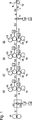
図1は、インフィード装置から4つの印刷装置および第2の引っ張りローラを介してロート状引き込みローラまでウェブをガイドする様子を略示し、
図2は、本刷りにおけるウェブの張力を略示し、
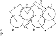
図3は、インキおよび場合により存在している湿し装置が図示されていないが印刷装置のゴム対ゴムを略示し、
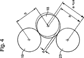
図4は、インキおよび場合により存在している湿し装置が図示されていないが印刷装置のゴム対対抗胴を略示し、
図5は、対毎に駆動されるゴム胴に対する駆動装置の電力消費に対する目標値の依存性の例を略示し、
図6は、印刷装置iに対する調整回路を略示している。
【0015】
図1には、ウェブB、例えば印刷材料ウェブBまたは巻き取り紙Bの、印刷機、殊に輪転印刷機を通るその途上での経過が略示されている。ウェブBは搬送方向Tにおいてローラチェンジャー01から引っ張りローラ03を有するインフィード装置02を介して例えば印刷装置06ないし09を通って第2の引っ張りローラ11に走行する。第2の引っ張りローラ11の後ろに例えば図示されていない転回ロッド、切断ナイフ、別の引っ張りまたはガイドローラおよび最後にロート状引き込みローラ12が続く。重要な引っ張りローラ03;11は有利にはそれぞれの独自の駆動装置13;14および駆動調整部16;17を装備している。インフィード装置02の前、インフィード装置02と第1の印刷装置06との間並びに最後の印刷装置09と引っ張りローラ11との間および引っ張りローラ11とロート状引き込みローラ12との前の自由な道で、有利な形態においてウェブBの張力S1;S2;S3;S4が測定される。このことは例えば測定ローラを介してまたは引っ張り装置の駆動モータの電力消費を介して行うことができる。
【0016】
ウェブBの張力の調整設定に対する出発点は、マルチウェブ作動においてロート状引き込み部にロート状引き込みローラ12を用いて複数のウェブBがまとめられるとき殊に、ロート状引き込みローラ12に対するそれぞれ相互の個々のウェブBの絶対および相対張力S4である(図1には複数のウェブが示唆されている)。従ってウェブBの張力の調整設定はロート状引き込みローラ12における所望のレベルから出発して行われる。有利には、インフィード装置02における位置調整によってウェブBの張力の基本レベルが確定される。ウェブBの張力に対するレベルの変化も有利な手法でインフィード装置02における張力S2の変化によって行われる。それ故にウェブBの緊張のために第1の引っ張りローラ03は機械速度に比べて遅れ目に作動される。本刷りにおいて、すなわち印刷速度であって、水および/またはインキが供給されて、第2の引っ張りローラ11は通例、自転する胴18、例えばゴム胴18の機械速度に対して早めに作動される。
【0017】
引っ張りローラ03;11並びにロート状引き込みローラ12および場合により第2の引っ張りローラ11とロート状引き込みローラ12との間に存在している駆動装置は生産速度を有する本刷りに対して、速度、トルクまたは回転位置について調整することができる。殊に引っ張りローラ03は、インフィード装置02と第1の印刷装置06との間の張力S2が持続的に目標値に戻されるように調整することができる。
【0018】
乾燥したウェブBが走っている場合には、第1の印刷装置06の前および最後の印刷装置09の後並びに印刷装置06ないし09の間でウェブBの同じ張力S2およびS3ないしS5ないしS7が生じているようにすると有利である。水および/またはインキを供給することによって、ウェブBの緊張ないし膨張特性並びに印刷装置06ないし09の個々の印刷個所を通過する際のウェブBの搬送特性が変化する。
【0019】
図2に略示されているように、本刷りの際の、第1の印刷装置06の前および最後に印刷装置09の後ろでの張力S2およびS3の基本調整設定は慣用の制御および調整技術によって、例えばウェブ張力、速度または位置調整される引っ張りローラ03、同様に調整されるロート状引き込みローラ12および/または図示されていないダンサーローラを介して行うことができる。ウェブBの普通は張力調整される状態は機械速度に関連して引っ張りローラ03を遅れ目にまた引っ張りローラ11を早めにすることで既に、印刷装置06ないし09の通過後および通過期間中、湿しの影響によって生じるウェブBの長さ変化を考慮する。横レジスタにおける対称的でかつ定常的なファン・アウト発生もここで既に考慮されるようにすることができる。
【0020】
印刷装置06ないし09の間でも、印刷のための胴入れ(Druck-An-Stellung)および水およびインキの供給の際、別の種類の紙への交換の際または例えば湿し媒体量の供給のようなプロセスパラメータの変化の際に、ウェブBの搬送特性および張力S5ないしS7が変化する。ウェブBが複数の印刷装置06ないし09を通過すると、搬送方向Tにおいて経路が先に行くに従って紙の特性の著しい変化が生じ、このためにも印刷装置、例えば06ないし09による走行の際にウェブBの異なった搬送特性が生じることになる。すなわち例えば紙の種類および印刷装置06ないし09間の自由な経路長に依存して、湿気がその時点で既に第3の印刷個所、例えばここでは第3の印刷装置08に達する前に完全にウェブBに入り込んでしまっている。
【0021】
そこで本刷りの期間では、印刷装置06ないし09の通過走行の際の搬送特性の変化または変動および/またはウェブBの張力S5ないしS7の変化に対抗するために、印刷装置06,07,08,09の、ウェブBを介してそれぞれ協働する2つの胴18の距離aを変えることができるようになっている(図3)。このことは、印刷胴入れに対するストッパが変化可能であるようにして行うことができる。ウェブBは距離aにおいて半径方向に相互に移動可能である胴18間を通りかつ印刷胴入れ位置においてこれらの間に張設されるようになっている。2つの、距離aをおいて相互に相対的に変化できるようになっている胴18はゴム対ゴム圧力において2つのゴム胴18を表している。例えば2つの協働するゴム胴18間の変化分Δaだけの距離aの変化は有利には同時に、それぞれのゴム胴18と該ゴム胴と協働する胴19、例えば版胴19との間の距離bが維持されるような仕方で行われる。
【0022】
普通は、ゴム胴18および版胴19の印刷胴入れないし胴外しは、ゴム胴18ないし版胴19の軸を収容している偏心体ブシュの旋回を介して相互に相対的に行われる。距離aの変化は例えば、第2の装置によって行うことができ、その際距離aが変化することで距離bが変化することがあってはならない。このことは例えば軸を収容する偏心体ブシュの第2の離心特性によって行うことができる。しかしこの変化のために例えば、機械に設けられている、既存の紙厚さ調整設定部も使用することができる。それぞれのゴム胴18および版胴19が相互に適当に配置されていれば、ゴム胴18の1つを直線的に移動することも考えられる。有利には図3において重ねて示されているように、距離aの変化は2つの協働するゴム胴18の一方の第2の偏心体ブシュの位置を介して行われる。距離aの設定は、例えば第2の偏心体ブシュの設定は、調整操作部材21を用いて例えばハイドロック、ニューマチック、電気的またはこれらの組み合わせて行われる。
【0023】
距離aを変化分Δaだけ変化することで行う、搬送特性の説明した変化は、ウェブBがゴム胴18の間にまだ張設されている、すなわち搬送される領域においてのみ行われる。それ故にウェブBの張力および搬送特性のこの調整は協働するゴム胴18の印刷胴入れ位置において行われる。ウェブBを介して協働する2つのゴム胴18の套面間の印刷ギャップdは印刷胴入れ位置においてはいずれのフェーズにおいても相応の場所におけるウェブBの厚さより小さいかまたは精々同じである。
【0024】
ところでウェブBの搬送特性の変化が1つまたは複数の印刷装置06ないし09で発生すると、距離aの変化は例えば変化分Δaの値だけ可能であり、そうすると結果的に印刷ギャップdが拡大または縮小されることになる。調整操作部材21の設定、ひいては距離aの変化Δaは操作者自らによって、例えばコントロール台から調整操作部材21に伝送される、設定値Δaとしての変化分Δaに対する値を介してまたは印刷装置において相応のボタン操作によって行うことができる。例えば、調整操作部材21は、ゴム胴18に対してその都度印刷胴入れ位置において対向設定されることになるストッパの位置を調整する。従って操作者は本刷りの期間、生産が行われている際に、印刷装置06ないし09間のウェブBの搬送特性に対して影響を及ぼすことができる。
【0025】
有利な形態において印刷装置06ないし09間のウェブBの搬送特性の調整は自動的に行われかつ例えばウェブBの張力に対する調整構想に組み込まれている。ここでこの構想は第1の印刷装置06の前および最後の印刷装置09の後ろで張力および伸びを調整して、紙の特性の変化によるウェブBの伸び率の変化を補償しようというものである。
【0026】
印刷装置06ないし09内ないしこれらの間でのウェブBの搬送特性の調整は有利な方法では駆動装置22の特性量を介して行われる。特性量X−istiの実際値X−istiは印刷装置iにおける駆動装置22において測定されかつ目標値X−Solliと比較される。偏差Δiは調整のために用いられかつ必要の場合には胴18間の距離aの変化のために用いられる。ゴム胴18の駆動装置22は有利には一定の周速ないし角速度が得られるように調整される。
【0027】
印刷装置06ないし09内ないしこれらの間でのウェブBの搬送特性の調整は有利には、ウェブBと協働する胴18の、例えばゴム胴18の駆動装置の(印刷装置iに対する)電力消費P−istiを介して行われる。電力消費の測定の際に版胴19および場合によってはこれと機械的に連結されているインキおよび/または湿し装置(図示されていない)の影響をできるだけ僅かに抑えるために、有利には各印刷装置06ないし09のそれぞれ2つのゴム胴18は対毎に独自の駆動装置22によって、またこれらと協働する版胴19は配属されているインキおよび場合によっては湿し装置と一緒に独自の駆動装置23によって駆動される。ゴム胴18のそれぞれの対は本発明の実施例においては機械的であり、例えば歯車または伝動ベルトを介して連結されている。しかしそれぞれのゴム胴18が個別に駆動されかつ電子的に同期されるようにしてもよい。張力ないし搬送特性の変化は、有利には回転数調整される駆動装置22において電力消費P−istiの変化となって現れる。
【0028】
ウェブBと協働する胴18の対の駆動装置22による電力消費P−istiは、それが相応に正規化されていることを前提とすれば、単位時間当たり駆動装置22によって行われた仕事に対する尺度であり、これはまた、胴の前後の張力の状態S2;S5;S6;S7;S3並びにウェブBの搬送特性に対する尺度を表している。これに応じて、前後に連続している印刷装置06ないし09に対して、駆動装置22の電力の消費に対する目標値P−Solli(印刷装置i)が確定される。これらは通例、搬送方向Tにおいて順番に現れる印刷装置06ないし09に対して相互に相異している(図5)。例えば、これら目標値P−Soll06は約4kWのP−Soll06を有する第1の印刷装置06から約7kWのP−Soll09を有する第4の印刷装置09まで上昇していく。しかし目標値として、2つの連続する印刷装置iおよびjのそれぞれの電力消費差ΔPi,j=P−isti−P−istjの目標値ΔPij−Soll、例えばΔP07,08=1kWを前以て与えることもできる。
【0029】
瞬時の電力消費P−istiはそれぞれの目標値P−Solliとまたは差分ΔPi,jは目標値ΔPij−Sollと比較される。目標値P−Solliないし目標値ΔPij−Sollからの偏差ΔiないしΔi,jが測定されると、このことは図6に略示されているように、調整回路において処理されかつ距離aの、値Δa分の変化が調整操作部材21を介して行われる。これにより、2つの協働するゴム胴18間の一層大きなもしくは一層小さな印刷ギャップdないしゴムブランケット張り出し具合、ひいては当該の印刷装置i(iは06;07;08;09のいずれか)におけるウェブBの変化した搬送特性が生じる。そこでウェブBの変化された搬送特性は今度はi番目の印刷装置の駆動装置22の電力消費P−istiを変える。この電力消費P−istiが監視されかつ調整回路に供給される。
【0030】
印刷胴入れ位置、すなわちウェブBがゴム胴18間に張設されていて、従って搬送されるときに印刷ギャップdを調整するために、駆動装置22からの別の適当な特性量も使用することができる。印刷装置06ないし09間の張力S5ないしS7に対する測定値も距離aないし印刷ギャップdの調整のために使用することができる。しかし既存の出力データを使用すれば有利である。この場合には大した付加コストが必要ないからである。
【0031】
胴18;23が一定のモーメントに調整される場合には、特性量は例えば、張力ないし搬送特性が変化すると変化する角速度であってよい。そこでこの変化に対して、距離aを変えることで対処することができる。
【0032】
ゴム胴18がウェブBを介して第2のゴム胴18ではなくて、対抗胴23(図4)と協働するときには、印刷胴入れのためにゴム胴18がウェブBを介して対抗胴23に当てつけられるかまたはその逆である。張力S5ないしS7を変えるために、ゴム胴18とこれに協働する対抗胴23の間の距離aが変化される。ウェブBを介して協働する2つの胴18;23、例えば2つのゴムブランケット胴18またはゴムブランケット胴18と対抗胴23は距離aの変化の目的で動かすことができる。説明してきた方法は、1つの対抗胴23が2つまたは複数のゴム胴と協働する変形も包含している。印刷胴入れにおけるウェブBのそれぞれの張力の変化は、逆圧胴23とゴムブランケット胴18との間の距離aを変えることによって行うことができる。
【0033】
ウェブBを介して協働し、かつウェブを張設する2つの胴18;23は印刷機における別の個所、抄紙機または圧延機、例えば塗装装置、乾燥機、上部構造、コーティングまたは圧延装置、カレンダー装置またはウェブBをガイドするその他の装置に配置されていてもよい。
【0034】
張力状態の変化ないし搬送特性の変化は張力状態を特徴付ける特性量を介して求められる。それは電力消費P−istiとは別の量、例えば胴18;23が一定のモーメントに関して調整される場合の角速度の変化も可能であるが、直接的な張力測定であってもよい。これらの量の変化は交互に影響し合う量「張力」および「搬送特性」に対する尺度を表している。それは殊に、印刷装置06;07;08;09の前後のウェブBの張力S2;S2;S5;S6;S7の状態の変化ないし結果的に生じる搬送特性の変化を示すものである。張力状態を特徴付ける特性量の、目標値X−Solliとの偏差は、−ウェブBの搬送特性に影響を及ぼす−胴18;23間の距離aを変化するために使用される。
【0035】
従って印刷装置06;07;08;09は印刷装置06;07;08;09の前、後ろおよび/またはこれらの間のウェブBの近似的に一定な張力S2;S2;S5;S6;S7について調整可能である。
【図面の簡単な説明】
【図1】 インフィード装置から4つの印刷装置および第2の引っ張りローラを介してロート状引き込みローラまでウェブをガイドする様子の略図である。
【図2】 本刷りにおけるウェブの張力の略図である。
【図3】 インキおよび場合により湿し装置が図示されていないが印刷装置のゴム胴対ゴム胴の略図である。
【図4】 インキおよび場合により湿し装置が図示されていないが印刷装置のゴム胴対対抗胴の略図である。
【図5】 対毎に駆動されるゴム胴に対する駆動装置の電力消費に対する目標値の依存性の例の略図である。
【図6】 印刷装置iに対する調整回路の略図である。
【符号の説明】
01 ローラチェンジャー
02 インフィード装置
03 引っ張りローラ
04 −
05 −
06 印刷装置、第1
07 印刷装置、第2
08 印刷装置、第3
09 印刷装置、第4
10 −
11 引っ張りローラ
12 ロート状引き込みローラ
13 駆動装置
14 駆動装置
15 −
16 駆動装置調整部
17 駆動装置調整部
18 胴、ゴム胴
19 胴、版胴
20 −
21 調整操作部材
22 駆動装置
23 対抗胴
B ウェブ、印刷材料ウェブ、巻き取り紙
T 搬送方向
a 距離(18)
b 距離(18,19)
d 印刷ギャップ
S1 張力
S2 張力
S3 張力
S4 張力
S5 張力
S6 張力
S7 張力
Δa 変化分、設定値
Δi 偏差
ΔPi 差
ΔPi,j−Soll 目標値
P−isti 印刷装置iに対する電力消費、ただしi=06ないし09
P−Solli 印刷装置iに対する目標値、ただしi=06ないし09
X−isti 実際値
X−Solli 目標値[0001]
The invention relates to a method for adjusting the tension of a web according to
[0002]
EP 0951993 A1 discloses a registration drive for a rotary printing press, in which the longitudinal elongation of the printing material web is determined from the web tension and operating value of the drive and the circumferential register of the cylinder or register roller. Compensated by position adjustment.
[0003]
DE 4211379 A1 describes a printing device in which a rubber cylinder is supported on an eccentric bushing whose position can be adjusted, in which the cylinder insertion is changed by swiveling via a first eccentric body axis and a second eccentric body. The printing width of the ink form roller with respect to the anilox roller is changed by turning about the axis.
[0004]
An object of the present invention is to provide a method for adjusting web tension.
[0005]
This object is a method for adjusting web tension according to
[0006]
The advantages obtained according to the invention are in particular the following: the printing device or printing unit can adjust the tensile stress or tension of the resulting web, for example a printing material web or web, in a simple manner. . This takes place via a change in pressure supply between the cooperating cylinders via the web, preferably the “rubber to rubber pressure” of the two cooperating rubber cylinders (Uebertragungszylinder) of one printing device. Is called.
[0007]
The transport properties of the web through the printing machine include, for example, the tension / elongation characteristics of each paper, and the resulting tension, wetness at each point in time, sensitivity to moisture, moisture penetration characteristics into the web, such as winding hardness. Although it appears to be different, it is subject to a number of influences, such as the roller's variation in its position in the drum and its location in elasticity and the location of the modulus of elasticity. In addition, it depends on lift and crimping force.
[0008]
The transport properties of the web through one or more printing devices of the printing press can be influenced and adjusted in an advantageous manner using the method of the invention, in which case it varies widely. There is no need to change the process guide, such as changing the thickness blanket or changing the wetness, for example. The change in web tension can be countered by changing the conveyance characteristics during the main printing period. It is also possible to use different blankets or different types of paper. This is because, using this method, the transport properties and print quality can be changed by changing the distance, not by the thickness of the blanket.
[0009]
Conversely, blankets having very different transport properties, different qualities and / or different thicknesses can also be used, with the desired web tension or web tension level between the printing devices. The attachment can be automatically held almost constant.
[0010]
Thus, for example, a given manufacturer's blanket acts "negatively transport", i.e. the web is "braked" and another "positive transport", i.e. the web is against winding at the nip. Additionally “extruded”.
[0011]
The transport characteristics also depend on the pressure of the blanket and the web.
[0012]
In an advantageous manner, the rubber cylinders are driven in pairs by a unique drive. The plate cylinder, which cooperates with the rubber cylinder, is configured to be driven independently with the ink and dampening device and is synchronized with the rubber cylinder only electronically. The advantages resulting from this are in particular that, for example, gear play is avoided when the rubber cylinder and the plate cylinder are mechanically connected, and the plate cylinder is hardly rotated with respect to the rubber cylinder and driven in synchronism with the angle. That is. Furthermore, for example, the (ink) leveling roller or doctor device is damped and not transmitted to the rubber cylinder due to its own drive for the plate cylinder and the ink and dampening device. For this reason, the printing progress is hardly disturbed.
[0013]
Embodiments of the invention are illustrated in the drawings and will now be described in detail.
[0014]
that time:
FIG. 1 schematically shows how a web is guided from an infeed device through four printing devices and a second pulling roller to a funnel-shaped pulling roller,
FIG. 2 schematically shows the tension of the web in the final printing,
FIG. 3 schematically illustrates the rubber-to-rubber of the printing device, although the ink and optional dampening device are not shown,
FIG. 4 schematically shows the rubber counter cylinder of the printing device, although the ink and optional dampening device are not shown,
FIG. 5 schematically shows an example of the dependence of the target value on the power consumption of the drive device for the rubber cylinders driven in pairs,
FIG. 6 schematically shows an adjustment circuit for the printing apparatus i.
[0015]
FIG. 1 schematically shows the course of a web B, for example a printing material web B or web B, on its way through a printing press, in particular a rotary printing press. The web B travels from the
[0016]
The starting point for the web B tension adjustment setting is the multi-web operation, particularly when a plurality of webs B are grouped together using a
[0017]
The pulling rollers 03; 11 and the funnel-
[0018]
When the dry web B is running, the same tension S2 and S3 to S5 to S7 of the web B before the
[0019]
As shown schematically in FIG. 2, the basic adjustment settings of tensions S2 and S3 before the
[0020]
Even between printing devices 06-09, when printing-druck-an-stellung and supplying water and ink, when switching to another type of paper or for example supplying a dampening medium amount When such process parameters change, the conveyance characteristics and tensions S5 to S7 of the web B change. When the web B passes through a plurality of
[0021]
Therefore, during the main printing period, in order to counter the change or fluctuation of the conveyance characteristics and / or the change of the tension S5 to S7 of the web B when the
[0022]
Normally, the printing cylinder insertion and removal of the
[0023]
The described change in the conveyance characteristics, which is performed by changing the distance a by the change amount Δa, is performed only in the region where the web B is still stretched between the
[0024]
However a change in the transport properties of the web B occurs in one or
[0025]
In an advantageous form, the adjustment of the transport properties of the web B between the
[0026]
The adjustment of the conveying properties of the web B in or between the
[0027]
The adjustment of the transport characteristics of the web B in or between the
[0028]
The power consumption P-ist i by the pair of
[0029]
The instantaneous power consumption P-ist i is compared with each target value P-Soll i or the difference ΔP i, j is compared with the target value ΔP ij -Soll. When the deviations Δ i to Δ i, j from the target value P-Soll i to the target value ΔP ij -Soll are measured, this is processed in the adjustment circuit and the distance as schematically shown in FIG. The change of a by the value Δa is performed through the
[0030]
Another suitable characteristic quantity from the
[0031]
In the case where the
[0032]
[0033]
Two
[0034]
The change in the tension state or the change in the conveyance characteristic is obtained through a characteristic amount characterizing the tension state. It can be a different amount than the power consumption P-ist i , for example a change in angular velocity when the
[0035]
Thus, the
[Brief description of the drawings]
FIG. 1 is a schematic diagram of guiding a web from an infeed device through four printing devices and a second pulling roller to a funnel-type pulling roller.
FIG. 2 is a schematic diagram of web tension in final printing.
FIG. 3 is a schematic diagram of a rubber cylinder to a rubber cylinder of a printing apparatus, although ink and possibly a dampening device are not shown.
FIG. 4 is a schematic illustration of a rubber cylinder versus a counter cylinder of a printing device, although ink and possibly a dampening device are not shown.
FIG. 5 is a schematic diagram of an example of the dependence of the target value on the power consumption of the drive for a rubber cylinder driven pairwise.
FIG. 6 is a schematic diagram of an adjustment circuit for the printing apparatus i.
[Explanation of symbols]
01 Roller changer 02 Infeed device 03 Pulling roller 04-
05 −
06 Printing device, 1st
07 Printing device, 2nd
08 Printing device, 3rd
09 Printing device, 4th
10-
11 Pulling
16 Driving
21
b Distance (18, 19)
d Print gap S1 tension S2 tension S3 tension S4 tension S5 tension S6 tension S7 tension Δa change, set value Δi deviation ΔP i difference ΔP i, j −Soll target value P-ist i power consumption for printing apparatus i, where i = 06 to 09
Target value for P-Soll i printing device i, where i = 06 to 09
X-ist i actual value X-Soll i target value
Claims (9)
なお、ウェブ(B)は該ウェブ(B)介して協働する、第1の胴(18)および第2の胴(18;23)を有する胴対の間で張設されるようになっており、かつ第1の胴(18)および第2の胴(18;23)は、印刷機の印刷装置(06;07;08;09)に配置されており、
前記胴(18;23)の前後のウェブ(B)の張力の状態を特徴付ける特性量の実際値(X−Isti)が測定されかつ目標値(X−Solli)と比較され、かつ
測定された実際値(X−Isti)の、目標値(X−Solli)からの偏差(Δi)に基づいて、ウェブ(B)と協働する胴(18;23)の距離(a)の変化(Δa)を行うウェブの張力の調整方法。A method of adjusting the tension (S2; S3; S5; S6; S7) of the web (B),
The web (B) is stretched between a pair of cylinders having a first cylinder (18) and a second cylinder (18; 23) that cooperate via the web (B). And the first cylinder (18) and the second cylinder (18; 23) are arranged in a printing device (06; 07; 08; 09) of the printing press,
Said barrel; is compared with (18 23) the actual value (X-Ist i) is measured and the target value of the characteristic quantity that characterizes the state of tension before and after the web (B) of (X-Soll i), and is measured Change of the distance (a) of the cylinder (18; 23) cooperating with the web (B) based on the deviation (Δi) of the actual value (X-Ist i ) from the target value (X-Soll i ) A method of adjusting the tension of the web for performing (Δa).
請求項1記載の方法。The printing machine method of claim 1, wherein the rotary printing press.
請求項1または2記載の方法。3. The method according to claim 1 , wherein the two cylinders (18; 23) are driven by at least one drive device (22).
請求項3記載の方法。4. The method according to claim 3 , wherein the actual value (X-Ist i ) of the characteristic quantity is determined in the drive device (22).
請求項1または2記載の方法。 3. The method according to claim 1 , wherein the two cylinders (18) cooperating with the web (B) are realized as rubber cylinders (18) and are driven by a common drive device (22).
該版胴(19)はゴム胴(18)の駆動装置(22)とは機械的に分離されている
請求項5記載の方法。Blanket cylinder (18) cooperates with a respective plate cylinder (19), and plate cylinder (19) is a drive of blanket cylinder (18) (22) according to claim 5, characterized in that the mechanically separated Method.
ゴム胴(18)は該ゴム胴(18)の駆動装置(22)とは機械的に分離されている版胴(19)と協働する
請求項1または2記載の方法。The first cylinder (18) is realized as a rubber cylinder (18) and the second cylinder (23) is realized as a counter cylinder (23) which cooperates via a web (B), and rubber. 3. A method according to claim 1, wherein the cylinder (18) cooperates with a plate cylinder (19) which is mechanically separated from the drive (22) of the rubber cylinder (18).
請求項7記載の方法。8. The method according to claim 7 , wherein a change ([Delta] a) in the distance (a) between the rubber cylinder (18) and the counter cylinder (23) is performed.
請求項6または8のいずれか1項記載の方法。When the distance (a) is changed by the change (Δa), the distance (b) between the rubber cylinder (18) and the plate cylinder (19) cooperating with the rubber cylinder is kept substantially constant. 9. A method according to any one of claims 6 or 8 .
Applications Claiming Priority (2)
| Application Number | Priority Date | Filing Date | Title |
|---|---|---|---|
| DE10035787A DE10035787C2 (en) | 2000-07-22 | 2000-07-22 | Process for regulating a web tension |
| PCT/DE2001/002717 WO2002007974A1 (en) | 2000-07-22 | 2001-07-19 | Method for regulating the tension of a web |
Publications (2)
| Publication Number | Publication Date |
|---|---|
| JP2004504190A JP2004504190A (en) | 2004-02-12 |
| JP4108471B2 true JP4108471B2 (en) | 2008-06-25 |
Family
ID=7649890
Family Applications (1)
| Application Number | Title | Priority Date | Filing Date |
|---|---|---|---|
| JP2002513693A Expired - Fee Related JP4108471B2 (en) | 2000-07-22 | 2001-07-19 | Web tension adjustment method |
Country Status (7)
| Country | Link |
|---|---|
| US (1) | US6810812B2 (en) |
| EP (1) | EP1303403B1 (en) |
| JP (1) | JP4108471B2 (en) |
| AT (1) | ATE407801T1 (en) |
| AU (1) | AU2001283779A1 (en) |
| DE (2) | DE10035787C2 (en) |
| WO (1) | WO2002007974A1 (en) |
Families Citing this family (28)
| Publication number | Priority date | Publication date | Assignee | Title |
|---|---|---|---|---|
| US6985789B2 (en) * | 2003-12-22 | 2006-01-10 | 3M Innovative Properties Company | Real-time determination of web tension and control using position sensors |
| WO2001056792A1 (en) * | 2000-02-04 | 2001-08-09 | Koenig & Bauer Aktiengesellschaft | Method for adjustment of a belt tension in a rotary press machine |
| DE10121945B4 (en) * | 2001-05-05 | 2007-04-05 | Koenig & Bauer Ag | Device for drawing in a material web |
| DE10129762B4 (en) * | 2001-06-20 | 2004-07-29 | Koenig & Bauer Ag | printing unit |
| DE10135773C5 (en) * | 2001-07-23 | 2009-07-09 | Koenig & Bauer Aktiengesellschaft | Method and device for controlling drives of a printing machine |
| JP4767457B2 (en) * | 2001-09-07 | 2011-09-07 | 住友重機械工業株式会社 | Control method and control apparatus for preventing occurrence of registration error during acceleration / deceleration in gravure printing press |
| DE10225824B4 (en) * | 2002-06-11 | 2006-11-02 | Koenig & Bauer Ag | Method for adjusting a web tension |
| DE10228242B4 (en) * | 2002-06-25 | 2004-09-16 | Koenig & Bauer Ag | Printing unit of a rotary printing press working in waterless offset printing with two printing points |
| DE10303122B4 (en) * | 2002-09-27 | 2005-10-06 | Koenig & Bauer Ag | Method for regulating the web tension of a multi-track system |
| DE10304495B4 (en) * | 2003-02-05 | 2015-04-16 | Koenig & Bauer Aktiengesellschaft | Method and arrangement for the synchronization of a single electric drive |
| DE10335885A1 (en) * | 2003-08-06 | 2005-03-17 | Man Roland Druckmaschinen Ag | Method and device for regulating the web tension and the cutting register error of a web-fed rotary printing press |
| DE10335888B4 (en) * | 2003-08-06 | 2008-03-13 | Man Roland Druckmaschinen Ag | Method and apparatus for controlling the total cut register error of a web-fed rotary press |
| DE10335887B4 (en) * | 2003-08-06 | 2007-11-08 | Man Roland Druckmaschinen Ag | Method and apparatus for controlling a cut register error and web tension of a web-fed rotary press |
| DE102005049345B4 (en) * | 2005-10-12 | 2010-07-15 | Koenig & Bauer Aktiengesellschaft | Devices for adjusting a position of a first rotating body relative to an adjacent second rotating body |
| DE102005054785B4 (en) | 2005-11-15 | 2010-08-19 | Koenig & Bauer Aktiengesellschaft | Method for operating a feeder of a printing press |
| FR2895305B1 (en) * | 2005-12-27 | 2009-04-17 | Goss Int Montataire Sa | PRINTING PRESS WITH ENHANCED BAND COMMITMENT AND METHOD OF ENGAGING CORRESPONDING BAND. |
| JP2008023751A (en) * | 2006-07-18 | 2008-02-07 | Mitsubishi Heavy Ind Ltd | Rotary press and operating method thereof |
| DE102006061252A1 (en) * | 2006-12-22 | 2008-06-26 | Man Roland Druckmaschinen Ag | Method and device for controlling a feeder |
| DE102007050891A1 (en) * | 2007-10-24 | 2009-04-30 | Siemens Ag | Adaptation of a controller in a rolling mill based on the scattering of an actual size of a rolling stock |
| DE102008053406A1 (en) * | 2008-10-27 | 2010-04-29 | Robert Bosch Gmbh | Method for automatic axis correction in a processing machine for processing a material web |
| DE102008056132A1 (en) | 2008-11-06 | 2010-05-12 | Robert Bosch Gmbh | Method for web tension adjustment |
| DE102009016206A1 (en) * | 2009-04-03 | 2010-10-14 | Robert Bosch Gmbh | Method for web tension adjustment |
| ES2348843B1 (en) * | 2009-05-14 | 2011-10-07 | Blanver Farmoquimica Ltda. | PROCEDURE FOR THE PREPARATION OF MICROCRYSTALLINE CELL. |
| CN103569414B (en) * | 2013-10-23 | 2015-09-09 | 广州市一路高包装机械技术有限公司 | Bag building mortion and wrapping machine |
| DE102016214963A1 (en) * | 2016-08-11 | 2018-02-15 | Robert Bosch Gmbh | Web processing machine with multiple webs and tension control |
| CN109318539A (en) * | 2018-12-13 | 2019-02-12 | 佛山科学技术学院 | A paper laminating machine |
| DE102020114894A1 (en) * | 2020-06-04 | 2021-12-09 | Broetje-Automation Gmbh | Device for processing fiber-reinforced plastic |
| IT202100032348A1 (en) * | 2022-01-11 | 2023-07-11 | Ipi Srl | METHOD AND APPARATUS FOR THE FORMATION OF CONTAINERS FILLED WITH A LIQUID AND SEALED |
Family Cites Families (15)
| Publication number | Priority date | Publication date | Assignee | Title |
|---|---|---|---|---|
| US4264957A (en) * | 1979-05-23 | 1981-04-28 | Zerand Corporation | Apparatus and method for register control in web processing apparatus |
| FR2623127A1 (en) * | 1987-11-12 | 1989-05-19 | Sarda Jean Claude | DEVICE FOR SUPPLYING AND RECEIVING A CONTINUOUS STRIP FOR PRINTING PRESSES OF SHEET LEAF TYPE |
| FR2633871B1 (en) * | 1988-07-07 | 1991-05-17 | Sarda Jean | MULTI-COLORED OFFSET PRINTS, VARIABLE FORMAT, FOR PRINTING CONTINUOUS TAPES |
| DE4211379C2 (en) * | 1992-04-04 | 1999-01-07 | Roland Man Druckmasch | Anilox offset printing unit with a short inking unit |
| DE19640649A1 (en) * | 1996-10-02 | 1998-04-16 | Roland Man Druckmasch | Drive for a sheet printing machine |
| JP2819283B2 (en) * | 1996-12-24 | 1998-10-30 | 株式会社東京機械製作所 | Continuous paper running tension control device |
| US6050185A (en) * | 1997-11-26 | 2000-04-18 | Heidelberger Druckmaschinen Ag | Printing unit for a web-fed rotary printing press |
| JP3180291B2 (en) * | 1997-11-10 | 2001-06-25 | 株式会社ミヤコシ | Paper tension control device in form printing machine |
| DE19753820A1 (en) | 1997-12-04 | 1999-06-10 | Roland Man Druckmasch | Device for the mutual adjustment of printing unit cylinders |
| EP0950519B1 (en) * | 1998-04-16 | 2001-08-29 | ABB Industrie AG | Method for self-adjusting the printing and the cutting register in rotary printing machines with several webs |
| DE59902522D1 (en) * | 1998-04-22 | 2002-10-10 | Wifag Maschf | Register-driven drive of a printing cylinder or a cutting register roller of a rotary printing machine |
| DE19834725A1 (en) * | 1998-07-31 | 2000-02-03 | Wifag Maschf | Web tension control device |
| JP3032763B1 (en) * | 1999-06-17 | 2000-04-17 | 株式会社東京機械製作所 | Paper feed unit with web paper running tension control device for rotary press |
| JP3182140B2 (en) * | 1999-09-14 | 2001-07-03 | 株式会社東京機械製作所 | Relief and Cylinder Control for Multicolor Printing Press |
| US6345574B1 (en) * | 2000-05-17 | 2002-02-12 | Heidelberger, Druckmaschinen Ag | Printing unit arrangement in a web-fed rotary printing press |
-
2000
- 2000-07-22 DE DE10035787A patent/DE10035787C2/en not_active Expired - Fee Related
-
2001
- 2001-07-19 EP EP01962576A patent/EP1303403B1/en not_active Expired - Lifetime
- 2001-07-19 DE DE50114313T patent/DE50114313D1/en not_active Expired - Fee Related
- 2001-07-19 AT AT01962576T patent/ATE407801T1/en not_active IP Right Cessation
- 2001-07-19 JP JP2002513693A patent/JP4108471B2/en not_active Expired - Fee Related
- 2001-07-19 AU AU2001283779A patent/AU2001283779A1/en not_active Abandoned
- 2001-07-19 US US10/312,596 patent/US6810812B2/en not_active Expired - Fee Related
- 2001-07-19 WO PCT/DE2001/002717 patent/WO2002007974A1/en not_active Ceased
Also Published As
| Publication number | Publication date |
|---|---|
| WO2002007974A1 (en) | 2002-01-31 |
| DE10035787C2 (en) | 2002-05-16 |
| DE10035787A1 (en) | 2002-01-31 |
| EP1303403A1 (en) | 2003-04-23 |
| US6810812B2 (en) | 2004-11-02 |
| ATE407801T1 (en) | 2008-09-15 |
| JP2004504190A (en) | 2004-02-12 |
| US20030188661A1 (en) | 2003-10-09 |
| EP1303403B1 (en) | 2008-09-10 |
| AU2001283779A1 (en) | 2002-02-05 |
| DE50114313D1 (en) | 2008-10-23 |
Similar Documents
| Publication | Publication Date | Title |
|---|---|---|
| JP4108471B2 (en) | Web tension adjustment method | |
| KR100546431B1 (en) | How to automatically adjust color and cutting register control on rotary printers with multiple webs | |
| US7040233B2 (en) | Method and device for controlling the drive units in a printing machine | |
| US5062360A (en) | Combined rotary web-fed printing machine, especially for the printing of securities | |
| JP3876225B2 (en) | A method for controlling web tension in a rotary printing press. | |
| JP3848162B2 (en) | Method for adjusting web tension in a rotary printing press | |
| CA2354759C (en) | Determining the presetting data for the cut register and/or color register (circumferential register) for printing mechanisms with no lineshaft | |
| US6578479B2 (en) | Method of operating a web-fed rotary printing machine | |
| KR101068027B1 (en) | Method for adjusting printing machine and register | |
| JP2004075391A (en) | Method and device for splitting crop mark setting | |
| JP2001310875A (en) | Device and method for controlling web tension | |
| JPH11314819A (en) | Method for controlling driving device for carrying paper web | |
| US7891530B2 (en) | Method for axial correction in a processing machine, as well as a processing machine | |
| JP3243422B2 (en) | Paper sheet processing and printing method, and apparatus for implementing the method | |
| JP4446293B2 (en) | Infeed device for rotary printing press | |
| JP3771611B2 (en) | Multi-color printing press width register correction device | |
| JP3943968B2 (en) | Rotary printing press and method for correcting initial printing position of plate cylinder of rotary printing press | |
| US20040144272A1 (en) | Multiple-Stand Gravure Printing Machine and Gravure Printing Process | |
| JP4131696B2 (en) | Operating method of printing press and offset rotary printing press | |
| US20080105153A1 (en) | Method for Controlling and/or Adjusting a Register in a Printing Machine and a Device for Controlling and/or Adjusting a Circumferential Register | |
| JP2000127352A (en) | Apparatus and method for controlling web tension for rotary press | |
| JP3611254B2 (en) | Multi-color printing press width register correction device | |
| JP3735221B2 (en) | Color tone stabilization method and apparatus for printing press | |
| EP1685049A1 (en) | Method for controlling the feeding of a web substrate into a printing press |
Legal Events
| Date | Code | Title | Description |
|---|---|---|---|
| A977 | Report on retrieval |
Free format text: JAPANESE INTERMEDIATE CODE: A971007 Effective date: 20060104 |
|
| A131 | Notification of reasons for refusal |
Free format text: JAPANESE INTERMEDIATE CODE: A131 Effective date: 20060322 |
|
| A131 | Notification of reasons for refusal |
Free format text: JAPANESE INTERMEDIATE CODE: A131 Effective date: 20070112 |
|
| A521 | Request for written amendment filed |
Free format text: JAPANESE INTERMEDIATE CODE: A523 Effective date: 20070221 |
|
| A131 | Notification of reasons for refusal |
Free format text: JAPANESE INTERMEDIATE CODE: A131 Effective date: 20070516 |
|
| A521 | Request for written amendment filed |
Free format text: JAPANESE INTERMEDIATE CODE: A523 Effective date: 20070813 |
|
| TRDD | Decision of grant or rejection written | ||
| A01 | Written decision to grant a patent or to grant a registration (utility model) |
Free format text: JAPANESE INTERMEDIATE CODE: A01 Effective date: 20080326 |
|
| A61 | First payment of annual fees (during grant procedure) |
Free format text: JAPANESE INTERMEDIATE CODE: A61 Effective date: 20080402 |
|
| FPAY | Renewal fee payment (event date is renewal date of database) |
Free format text: PAYMENT UNTIL: 20110411 Year of fee payment: 3 |
|
| R150 | Certificate of patent or registration of utility model |
Free format text: JAPANESE INTERMEDIATE CODE: R150 |
|
| LAPS | Cancellation because of no payment of annual fees |