JP4122246B2 - Load sensor - Google Patents
Load sensor Download PDFInfo
- Publication number
- JP4122246B2 JP4122246B2 JP2003067769A JP2003067769A JP4122246B2 JP 4122246 B2 JP4122246 B2 JP 4122246B2 JP 2003067769 A JP2003067769 A JP 2003067769A JP 2003067769 A JP2003067769 A JP 2003067769A JP 4122246 B2 JP4122246 B2 JP 4122246B2
- Authority
- JP
- Japan
- Prior art keywords
- load
- pressure
- operating body
- diaphragm
- elastic body
- Prior art date
- Legal status (The legal status is an assumption and is not a legal conclusion. Google has not performed a legal analysis and makes no representation as to the accuracy of the status listed.)
- Expired - Lifetime
Links
Images


Landscapes
- Measurement Of Force In General (AREA)
Description
【0001】
【発明の属する技術分野】
本発明は、ダイヤフラムに歪センサを取付け所定の荷重までの押圧に対して荷重を検出する荷重センサに関し、特に薄型で荷重を精度よく検出できる荷重センサに関する。
【0002】
【従来の技術】
従来、歩行ロボットの脚などに用いられる荷重センサには、ダイヤフラムに歪センサを取付け、そこから出力される信号によって荷重を検出するものが用いられている。このような荷重センサは広く知られており、例えば特開平7−280671のように、ダイヤフラムの上部に操作体を設けて荷重を検出するものがある。なお、この例においては、操作体の前後左右の動きを検出するために操作体にはコイル状のバネを設けている。
【0003】
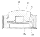
一方、上方からの荷重を検出する荷重センサにおいては、過大荷重や衝撃荷重に対して、ダイヤフラムが破損しないように機械的なストッパを設けることがある。この場合においては、例えば図5のように中心部を薄肉状の感圧部12aとし、この感圧部12aに歪センサを取付けたダイヤフラム12の上面に、ゴムからなる駆動体11を設け、さらにそれを取囲むように操作体10を設ける。
【0004】
操作体10は、荷重がかかっていない状態では、ダイヤフラム12との間に隙間を生じるように形成される。操作体10に荷重をかけると、駆動体11を介してダイヤフラム12の感圧部12aに歪みを生じ、歪センサによって荷重を検出する。操作体10に所定以上の荷重をかけた場合、操作体10の下面はダイヤフラム12の厚肉部12bに当接して、感圧部12aにはそれ以上大きな荷重がかからないようにすることで、過大荷重や衝撃荷重に対して感圧部12aを保護することができる。これに近い荷重センサとして例えば特許文献1〜3に示すようなものがある。
【特許文献1】
実開平6−7030号公報
【特許文献2】
特開平7−77467号公報
【特許文献3】
特開平5−142076号公報
【0005】
【発明が解決しようとする課題】
しかし、上記従来の荷重センサにおいては、以下に述べるような問題点を有していた。
操作体とダイヤフラムの間にゴムからなる駆動体を設けた場合においては、ゴムの寸法精度や環境温度の変化などによって、検出荷重にバラツキを生じやすく、精度の面で問題がある。特に、設計上は所定の荷重において操作体がダイヤフラムに当接するようにされるものの、上記要因によってバラツキが生じると、操作体がダイヤフラムに当接する荷重にもバラツキが生じる。ゴムは、荷重に対して線形に変位せず、荷重の低い段階で大きく変位して、ある程度の荷重になるとほとんど変位しなくなる。したがって、駆動体のわずかな特性の変化により、ダイヤフラムの感圧部に非常に大きな荷重がかかる場合があり、ダイヤフラムの破損を招くことがあった。
【0006】
本発明は、上記問題点を解決すべくなされたものであり、荷重を精度よく検出することができると共に、過大荷重や衝撃荷重に対して破損しにくい荷重センサを提供することを目的とする。
【0007】
【課題を解決するための手段】
上記課題を解決するため、本発明に係る荷重センサは、中心部に薄肉状の感圧部を形成し、該感圧部に歪み素子が取り付けられた板状の圧力検出手段を備え、
上記感圧部には荷重を加える操作体によって押圧される駆動体を戴置した荷重センサにおいて、
上記駆動体と操作体を連結するための、荷重に対する変位量が線形性を有する弾性体を設け、
上記圧力検出手段には感圧部の外周に厚肉部を形成し、該厚肉部により上記圧力検出手段を支持し、
上記駆動体は上記感圧部に当接する鍔部を有し、該鍔部に係合するように上記弾性体が配置され、該弾性体を介して上記操作体が上記駆動体に連結され、
上記操作体は、上記駆動体が略納まるように空洞が内部に形成され、上記弾性体を介して上記駆動体を上記感圧部に押圧すると共に、所定の荷重において下面が上記圧力検出手段の厚肉部に当接することを特徴として構成されている。
【0008】
本発明によれば、操作体と駆動体は荷重に対する変位量が線形性を有する弾性体を介して連結され、操作体は弾性体を介して駆動体を感圧部に押圧しているので、安定的に荷重を検出することができると共に、機械的ストッパの作動する荷重を環境条件等によらず略一定とすることができる。
【0011】
さらに、本発明に係る荷重センサは、上記操作体と上記厚肉部の間には上記弾性体が荷重に対して線形に変位する限界変位量より小さな隙間を設けていることを特徴として構成されている。
【0012】
本発明によれば、操作体と圧力検出手段の隙間を弾性体の限界変位量より小さくしているので、弾性体が線形に変位する領域のみ用いることにより、常に一定の荷重で駆動体を圧力検出手段に当接させることができる。
【0013】
さらにまた、本発明に係る荷重センサは、上記操作体は上記駆動体を押圧する段部を有し、上記弾性体は皿バネによって構成されて上記鍔部と段部にそれぞれ係合し、上記駆動体と操作体を連結することを特徴として構成されている。
【0014】
本発明によれば、弾性体を皿バネにて構成しているので、弾性体の変位する方向の長さを短くしても、弾性体を線形に変位させることができる。
【0015】
【発明の実施の形態】
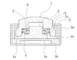
本発明の実施形態について、図に沿って詳細に説明する。図1は、本実施形態における荷重センサの縦断面図を示している。また、図2は、本実施形態における荷重センサに用いられる圧力検出手段たるダイヤフラム4の平面図を示している。本実施形態における荷重センサは、円盤形状からなるダイヤフラム4の中心部を薄肉状として感圧部4aを形成し、この感圧部4aには歪センサ7を4つ設け、感圧部4aの上面には駆動体2を戴置すると共に、駆動体2は弾性体3を介して操作体1に連結されているものである。
【0016】
ダイヤフラム4は、図1及び図2に示すように、円盤形状に形成され、中心部を薄肉状にして撓みやすくされる。中心部の薄肉状の部分には、その中心付近に2つ歪センサ7、7を設け、周縁部に近い場所にも中心付近の歪センサ7、7を挟んで略対称な位置に、それぞれ1つずつ歪センサ7、7を設けて、感圧部4aを構成する。
【0017】
感圧部4aは、上方から荷重をかけられると、中心付近には圧縮方向の歪みが生じ、周縁部付近には引っ張り方向の歪みが生じる。各歪センサ7、7は、図示しないブリッジ回路に接続されて、荷重を検出する。ブリッジ回路は、従来のものと同様である。ダイヤフラム4の周縁部は厚肉状とされ、厚肉部4bを構成する。厚肉部4bは、図1に示すように、その底面及び側面をケース体5に当接され、ダイヤフラム4を支えている。
【0018】
ダイヤフラム4の感圧部4aには駆動体2が戴置される。駆動体2は、金属材料によって形成され、感圧部4aに当接する部分を幅広に形成した鍔部2aを有した二段の円筒形状からなる。鍔部2aの底面は、ダイヤフラム4の感圧部4aに当接、押圧するために、鍔部2aはその直径を感圧部4aの直径よりも小さく形成される。
【0019】
駆動体2は、操作体1によって押圧される。操作体1は、樹脂材料によって形成され、駆動体2に比べて幅広とされると共に、駆動体2を内部に略納めることができるように空洞を形成されている。操作体1の内部の空洞は、駆動体2の鍔部2aに合わせて、二段の円筒形状からなり、段部1bを形成されている。また、操作体1の上面は、略球面状に形成されており、荷重を加えられた場合にその荷重が均一に駆動体2に伝わるようにされている。
【0020】
操作体1と駆動体2は、弾性体3によって連結される。弾性体3には、略円形の板状からなるリング形状を有すると共に、内周から外周に向かって傾斜状に形成された部材を互いに対向するように重ねた皿バネを用いる。皿バネは、変位する方向の高さを比較的低く抑えることができ、その場合でも荷重の低い領域からストロークが略線形に変位するため、操作体1と駆動体2の間隔をそれほど大きくする必要がなく、したがって荷重センサの薄型化を図ることができる。
【0021】
弾性体3は、操作体1の段部1bと、駆動体2の鍔部2aにそれぞれ係合し、駆動体2の鍔部2aより上部の、幅狭に形成された部分を取囲むように設けられる。また、弾性体3と操作体1の段部1bとの間にはワッシャ6を設けている。操作体1は樹脂材料から形成されているために、皿バネから局所的に荷重を受けた場合には、へこみ等を生じる可能性があるため、ワッシャ6を設けることで段部1bにおける荷重を分散させてへこみ等を生じないようにしている。
【0022】
操作体1の底面は、略平面状に形成されて当接面1aを構成し、荷重をかけられていない状態において、ダイヤフラム4との間に隙間を有している。操作体1に荷重を加えると、所定の荷重までは弾性体3を介して駆動体2を押圧し、所定の荷重に達すると当接面1aはダイヤフラム4の厚肉部4bに当接、押圧することで、駆動体2にはそれ以上の荷重はかからないので、ダイヤフラム4の感圧部4aの過大荷重や衝撃荷重による破損を防ぐことができる。
【0023】
操作体1の当接面1aを所定の荷重でダイヤフラム4に当接させるためには、弾性体3の荷重に対するストロークの関係から、当接面1aとダイヤフラム4の隙間の間隔を決めることで可能となる。図4には弾性体3の荷重に対するストロークの関係を示す。皿バネのストロークは、荷重に対して略比例しているので、当接面1aとダイヤフラム4を当接させる設定荷重に対して設ける隙間の間隔を容易に求めることができる。
【0024】
ただし、荷重とストロークの関係はある一定の荷重を超えると比例関係とはならなくなる。この荷重を限界荷重といい、この限界荷重における皿バネのストロークを限界変位量という。したがって、当接面1aとダイヤフラム4を当接させる設定荷重は、皿バネの限界荷重より小さな値とする。すなわち隙間の設定値は限界変位量よりも小さくする必要がある。
【0025】
図4には、皿バネの荷重に対するストロークと共に、ゴムを用いた場合の荷重に対するストロークを示している。この図のようにゴムを用いると荷重の小さい領域で荷重に対してストロークが大きく変化する。また、ゴムは環境温度によってその硬度が変化するために、そのわずかな違いによって設定荷重に誤差が生じて、操作体1の動作が不安定となる。皿バネを用いると、荷重に対するストロークは限界荷重に達するまでは略比例関係にあり、また環境温度に対する特性の変化も少ないために、安定して荷重を検出でき、また一定の荷重で操作体1の当接面1aをダイヤフラム4に当接させることができる。
【0026】
図3には、本実施形態における荷重センサの組立図を示す。荷重センサを構成するダイヤフラム4、駆動体2、操作体1、及び弾性体3は、ケース体5の中に納められている。ケース体5は、固定板5bとカバー5aからなり、固定板5bにはダイヤフラム4が取付けられる。ダイヤフラム4の厚肉部4bの底面は、固定板5bに戴置され、操作体1からの荷重を支えている。ダイヤフラム4の感圧部4aには歪センサ7、7が設けられ、感圧部4aの上面には駆動体2が戴置される。そして、その鍔部2aには皿バネからなる弾性体3を係合し、弾性体3の上端にはワッシャ6を設ける。
【0027】
さらに、駆動体2及び弾性体3を略覆うように操作体1を配置し、その段部1bをワッシャ6に当接させる。この段階で、操作体1の底面である当接面1aとダイヤフラム4との隙間は、上述のような所定の荷重を加えられた場合に当接面1aがダイヤフラム4に当接する間隔となる。ダイヤフラム4及び操作体1の周囲はカバー5aによって取囲まれ、このカバー5aは固定板5bに固定される。カバー5aを固定板5bに固定した状態において、操作体1はその上面がカバー5aの上面から突出するように背高状に形成され、外部からの荷重を受ける構造とされている。
【0028】
以上の構成から、本実施形態における荷重センサは、以下のように動作する。操作体1に外部から荷重を加えられた場合、操作体1は弾性体3を介して駆動体2を押圧し、駆動体2はダイヤフラム4の感圧部4aを押圧する。ダイヤフラム4の感圧部4aに設けられた歪センサ7を含む図示しないブリッジ回路は、感圧部4aの撓みに応じた信号を出力して、荷重を検出する。
【0029】
外部からの荷重が大きくなると、弾性体3は圧縮され縮んでいき、操作体1は下方に押下げられる。やがて、荷重がある一定の値に達すると、操作体1の底面である当接面1aは、ダイヤフラム4の厚肉部4bに当接し、さらに荷重を増すと厚肉部4bを押圧する。当接面1aが厚肉部4bに当接すると、弾性体3はそれ以上縮むことはなく、駆動体2にそれ以上の荷重はかからなくなる。したがって、感圧部4aにかかる荷重もそれ以上大きくなることはなく、ダイヤフラム4を過大荷重や衝撃荷重から保護することができる。
【0030】
【発明の効果】
以上のように本発明によれば、操作体と駆動体は弾性体を介して連結されており、弾性体は荷重に対してストロークが略比例するので、荷重を安定的に検出することができ、また周辺環境によらず略一定荷重で操作体を圧力検出手段に当接させることができ、過大荷重や衝撃荷重から圧力検出手段の破損を防ぐことができる。さらに、操作体は弾性体を介して駆動体を圧力検出手段に押圧しているので、圧力検出手段に対して均一に荷重をかけることができ、荷重の検出を正確に行うことができる。
【0031】
また、本発明によれば、操作体からの過大荷重や衝撃荷重を厚肉部で受けることができるので、より強い過大荷重や衝撃荷重に耐える荷重センサとすることができる。
【0032】
さらに、本発明によれば、操作体と圧力検出手段の隙間を弾性体の限界変位量より小さくしているので、弾性体が線形に変位する領域のみ用いることにより、常に一定の荷重で駆動体を圧力検出手段に当接させることができ、安定した動作を行わせることができる。
【0033】
さらにまた、本発明によれば、弾性体を皿バネにて構成しているので、弾性体の変位する方向の長さを短くしても、弾性体を線形に変位させることができ、荷重センサを薄型化することができる。
【図面の簡単な説明】
【図1】本実施形態における荷重センサの縦断面図である。
【図2】本実施形態における荷重センサに用いられるダイヤフラムの平面図である。
【図3】本実施形態における荷重センサの組立図である。
【図4】ゴム及び皿バネの荷重に対するストロークを模式的に示した図である。
【図5】従来の荷重センサの縦断面図である。
【符号の説明】
1 操作体
1a 当接面
1b 段部
2 駆動体
2a 鍔部
3 弾性体
4 ダイヤフラム
4a 感圧部
4b 厚肉部
5 ケース体
5a カバー
5b 固定板
6 ワッシャ
7 歪センサ[0001]
BACKGROUND OF THE INVENTION
The present invention relates to a load sensor that attaches a strain sensor to a diaphragm and detects a load in response to pressing up to a predetermined load, and particularly relates to a thin load sensor that can detect a load with high accuracy.
[0002]
[Prior art]
Conventionally, a load sensor used for a leg of a walking robot has a strain sensor attached to a diaphragm and detects a load by a signal output therefrom. Such a load sensor is widely known. For example, as disclosed in Japanese Patent Application Laid-Open No. 7-280671, there is a sensor that detects a load by providing an operating body on an upper portion of a diaphragm. In this example, a coiled spring is provided on the operating body in order to detect the front / rear and left / right movements of the operating body.
[0003]
On the other hand, in a load sensor that detects a load from above, a mechanical stopper may be provided to prevent the diaphragm from being damaged by an excessive load or an impact load. In this case, for example, as shown in FIG. 5, the central portion is a thin pressure-
[0004]
The
[Patent Document 1]
Japanese Utility Model Publication No. 6-7030 [Patent Document 2]
JP-A-7-77467 [Patent Document 3]
Japanese Patent Laid-Open No. 5-142076
[Problems to be solved by the invention]
However, the conventional load sensor has the following problems.
When a driving body made of rubber is provided between the operating body and the diaphragm, the detected load is likely to vary due to changes in the dimensional accuracy of the rubber, environmental temperature, etc., and there is a problem in terms of accuracy. In particular, although the operating body comes into contact with the diaphragm at a predetermined load by design, when variation occurs due to the above factors, the load with which the operating body comes into contact with the diaphragm also varies. The rubber does not displace linearly with respect to the load, but greatly displaces at a low load stage, and hardly displaces at a certain load. Therefore, a very large load may be applied to the pressure-sensitive portion of the diaphragm due to a slight change in the characteristics of the driver, which may cause the diaphragm to break.
[0006]
The present invention has been made to solve the above problems, and an object of the present invention is to provide a load sensor that can detect a load with high accuracy and is not easily damaged by an excessive load or an impact load.
[0007]
[Means for Solving the Problems]
In order to solve the above-described problem, a load sensor according to the present invention includes a plate-like pressure detection unit in which a thin pressure-sensitive part is formed in a central part, and a strain element is attached to the pressure-sensitive part.
In the load sensor in which the driving body pressed by the operating body that applies a load is placed on the pressure-sensitive portion,
An elastic body for connecting the driving body and the operating body and having a linear displacement amount with respect to a load is provided,
In the pressure detection means, a thick part is formed on the outer periphery of the pressure sensing part, and the pressure detection means is supported by the thick part,
The drive body has a flange portion that contacts the pressure-sensitive portion, the elastic body is disposed so as to engage with the flange portion, and the operating body is coupled to the drive body via the elastic body,
The operating body has a cavity formed therein so that the driving body can be substantially accommodated , presses the driving body against the pressure-sensitive portion via the elastic body, and a lower surface of the pressure detecting means at a predetermined load. It is configured to abut on the thick portion .
[0008]
According to the present invention, the operating body and the driving body are coupled via an elastic body having a linear displacement with respect to the load, and the operating body presses the driving body against the pressure-sensitive portion via the elastic body. The load can be detected stably, and the load at which the mechanical stopper operates can be made substantially constant regardless of the environmental conditions.
[0011]
Further, the load sensor according to the present invention is characterized in that a gap smaller than a limit displacement amount in which the elastic body is linearly displaced with respect to the load is provided between the operation body and the thick portion. ing.
[0012]
According to the present invention, since the gap between the operating body and the pressure detecting means is made smaller than the limit displacement amount of the elastic body, the driving body is always pressurized with a constant load by using only the region where the elastic body is linearly displaced. It can be brought into contact with the detection means.
[0013]
Furthermore, a load sensor according to the present invention, the control body has a step portion for pressing the driving body, the elastic body is constituted by the disc spring engaged with each said flange portion and the stepped portion, the The driving body and the operating body are connected to each other.
[0014]
According to the present invention, since the elastic body is constituted by the disc spring, the elastic body can be linearly displaced even if the length of the elastic body in the direction of displacement is shortened.
[0015]
DETAILED DESCRIPTION OF THE INVENTION
Embodiments of the present invention will be described in detail with reference to the drawings. FIG. 1 shows a longitudinal sectional view of a load sensor in the present embodiment. FIG. 2 is a plan view of the
[0016]
As shown in FIGS. 1 and 2, the
[0017]
When pressure is applied from above, the pressure-
[0018]
The driving
[0019]
The driving
[0020]
The operating
[0021]
The
[0022]
The bottom surface of the operating
[0023]
In order to bring the contact surface 1a of the operating
[0024]
However, the relationship between the load and the stroke does not become proportional when a certain load is exceeded. This load is called the limit load, and the disc spring stroke at this limit load is called the limit displacement. Therefore, the set load for bringing the contact surface 1a into contact with the
[0025]
FIG. 4 shows the stroke with respect to the load when rubber is used together with the stroke with respect to the load of the disc spring. When rubber is used as shown in this figure, the stroke changes greatly with respect to the load in a region where the load is small. Further, since the hardness of rubber changes depending on the environmental temperature, an error occurs in the set load due to the slight difference, and the operation of the operating
[0026]
In FIG. 3, the assembly drawing of the load sensor in this embodiment is shown. The
[0027]
Further, the operating
[0028]
From the above configuration, the load sensor in the present embodiment operates as follows. When a load is applied to the
[0029]
When the load from the outside increases, the
[0030]
【The invention's effect】
As described above, according to the present invention, the operating body and the drive body are connected via the elastic body, and the stroke of the elastic body is approximately proportional to the load, so that the load can be detected stably. In addition, the operating body can be brought into contact with the pressure detection means with a substantially constant load regardless of the surrounding environment, and damage to the pressure detection means can be prevented from an excessive load or an impact load. Further, since the operating body presses the driving body against the pressure detecting means via the elastic body, a load can be applied uniformly to the pressure detecting means, and the load can be detected accurately.
[0031]
Further, according to the present invention, since an excessive load or impact load from the operating body can be received by the thick part, a load sensor that can withstand a stronger excessive load or impact load can be obtained.
[0032]
Furthermore, according to the present invention, since the gap between the operating body and the pressure detecting means is made smaller than the limit displacement amount of the elastic body, the driving body is always kept at a constant load by using only the region where the elastic body is linearly displaced. Can be brought into contact with the pressure detecting means, and a stable operation can be performed.
[0033]
Furthermore, according to the present invention, since the elastic body is constituted by the disc spring, the elastic body can be linearly displaced even if the length of the elastic body in the direction of displacement is shortened, and the load sensor Can be made thinner.
[Brief description of the drawings]
FIG. 1 is a longitudinal sectional view of a load sensor according to an embodiment.
FIG. 2 is a plan view of a diaphragm used in the load sensor in the present embodiment.
FIG. 3 is an assembly diagram of a load sensor in the present embodiment.
FIG. 4 is a diagram schematically showing a stroke with respect to a load of rubber and a disc spring.
FIG. 5 is a longitudinal sectional view of a conventional load sensor.
[Explanation of symbols]
DESCRIPTION OF
Claims (3)
上記感圧部には荷重を加える操作体によって押圧される駆動体を戴置した荷重センサにおいて、
上記駆動体と操作体を連結するための、荷重に対する変位量が線形性を有する弾性体を設け、
上記圧力検出手段には上記感圧部の外周に厚肉部を形成し、該厚肉部により上記圧力検出手段を支持し、
上記駆動体は上記感圧部に当接する鍔部を有し、該鍔部に係合するように上記弾性体が配置され、該弾性体を介して上記操作体が上記駆動体に連結され、
上記操作体は、上記駆動体が略納まるように空洞が内部に形成され、上記弾性体を介して上記駆動体を上記感圧部に押圧すると共に、所定の荷重において下面が上記圧力検出手段の厚肉部に当接することを特徴とする荷重センサ。A thin pressure-sensitive part is formed at the center, and plate-like pressure detection means having a strain element attached to the pressure-sensitive part is provided,
In the load sensor in which the driving body pressed by the operating body that applies a load is placed on the pressure-sensitive portion,
An elastic body for connecting the driving body and the operating body and having a linear displacement amount with respect to a load is provided,
The pressure detecting means is formed with a thick part on the outer periphery of the pressure sensitive part, and the pressure detecting means is supported by the thick part,
The drive body has a flange portion that contacts the pressure-sensitive portion, the elastic body is disposed so as to engage with the flange portion, and the operating body is coupled to the drive body via the elastic body,
The operating body has a cavity formed therein so that the driving body can be substantially accommodated , presses the driving body against the pressure-sensitive portion via the elastic body, and a lower surface of the pressure detecting means at a predetermined load. A load sensor that abuts against a thick portion .
Priority Applications (2)
| Application Number | Priority Date | Filing Date | Title |
|---|---|---|---|
| JP2003067769A JP4122246B2 (en) | 2003-03-13 | 2003-03-13 | Load sensor |
| US10/796,940 US7343223B2 (en) | 2003-03-13 | 2004-03-10 | Robot apparatus and load sensor |
Applications Claiming Priority (1)
| Application Number | Priority Date | Filing Date | Title |
|---|---|---|---|
| JP2003067769A JP4122246B2 (en) | 2003-03-13 | 2003-03-13 | Load sensor |
Publications (2)
| Publication Number | Publication Date |
|---|---|
| JP2004279080A JP2004279080A (en) | 2004-10-07 |
| JP4122246B2 true JP4122246B2 (en) | 2008-07-23 |
Family
ID=33285286
Family Applications (1)
| Application Number | Title | Priority Date | Filing Date |
|---|---|---|---|
| JP2003067769A Expired - Lifetime JP4122246B2 (en) | 2003-03-13 | 2003-03-13 | Load sensor |
Country Status (1)
| Country | Link |
|---|---|
| JP (1) | JP4122246B2 (en) |
Cited By (1)
| Publication number | Priority date | Publication date | Assignee | Title |
|---|---|---|---|---|
| JP2015161531A (en) * | 2014-02-26 | 2015-09-07 | アルプス電気株式会社 | LOAD DETECTING DEVICE AND ELECTRONIC DEVICE USING THE LOAD DETECTING DEVICE |
Families Citing this family (8)
| Publication number | Priority date | Publication date | Assignee | Title |
|---|---|---|---|---|
| JP4751778B2 (en) * | 2006-06-23 | 2011-08-17 | アイシン精機株式会社 | Load detection device and manufacturing method thereof |
| ES2342553T3 (en) * | 2006-12-02 | 2010-07-08 | Texmag Gmbh Vertriebsgesellschaft | ROLLER WITH A FORCE SENSOR. |
| JP6568544B2 (en) * | 2015-01-13 | 2019-08-28 | 北陸電気工業株式会社 | Force sensor unit |
| JP6390559B2 (en) * | 2015-09-02 | 2018-09-19 | トヨタ自動車株式会社 | Load detection device |
| JP2018054293A (en) * | 2016-09-26 | 2018-04-05 | 日立オートモティブシステムズ株式会社 | Load sensor |
| US11175192B2 (en) * | 2019-09-20 | 2021-11-16 | Measurement Specialties, Inc. | Sensor assembly having an overload stop |
| CN114659698B (en) * | 2022-03-06 | 2024-04-09 | 淮安市格洋浩瑞电子科技有限公司 | Impact-resistant high-stability flat membrane type pressure sensor |
| JP2024062069A (en) * | 2022-10-24 | 2024-05-09 | 長野計器株式会社 | Load Measuring Device |
-
2003
- 2003-03-13 JP JP2003067769A patent/JP4122246B2/en not_active Expired - Lifetime
Cited By (1)
| Publication number | Priority date | Publication date | Assignee | Title |
|---|---|---|---|---|
| JP2015161531A (en) * | 2014-02-26 | 2015-09-07 | アルプス電気株式会社 | LOAD DETECTING DEVICE AND ELECTRONIC DEVICE USING THE LOAD DETECTING DEVICE |
Also Published As
| Publication number | Publication date |
|---|---|
| JP2004279080A (en) | 2004-10-07 |
Similar Documents
| Publication | Publication Date | Title |
|---|---|---|
| US9823144B2 (en) | Load sensor | |
| US20130247689A1 (en) | Force sensor | |
| JPS62191730A (en) | Pressure sensor | |
| JPH0349060B2 (en) | ||
| US20180238749A1 (en) | Force sensor unit | |
| JP2008532026A (en) | Load cell | |
| JP2004279080A (en) | Load sensor | |
| JP7508744B2 (en) | Sensor assembly having multiple range structure | |
| CN117677828A (en) | Pressure sensor with contact recognition of deflection of membrane and pressure sensor system and method for generating pressure signal | |
| WO2019116817A1 (en) | Load sensor, and electric brake | |
| EP1498804B1 (en) | Analog input device | |
| US5040640A (en) | Piezoresistive elevator button | |
| US5621178A (en) | Piezoelectric sensor system | |
| JP7113487B2 (en) | pulse wave sensor | |
| US3537318A (en) | Transducer overload protection means | |
| CN114689227B (en) | A thin film pressure sensor | |
| CN112345125B (en) | Seal glass geometry for enhanced thick film piezoresistive pressure sensor sensitivity | |
| JP4239427B2 (en) | Pedal force detection device | |
| JP2018205217A (en) | Load sensor | |
| JPH08145819A (en) | Load sensor | |
| CN223347318U (en) | A touch input unit based on pressure conversion | |
| US8884636B2 (en) | Sensor | |
| JPH0592656U (en) | load cell | |
| JPH0510808A (en) | Capacitive load cell | |
| JP4520195B2 (en) | Contact displacement sensor |
Legal Events
| Date | Code | Title | Description |
|---|---|---|---|
| A621 | Written request for application examination |
Free format text: JAPANESE INTERMEDIATE CODE: A621 Effective date: 20060112 |
|
| A977 | Report on retrieval |
Free format text: JAPANESE INTERMEDIATE CODE: A971007 Effective date: 20071113 |
|
| A131 | Notification of reasons for refusal |
Free format text: JAPANESE INTERMEDIATE CODE: A131 Effective date: 20071119 |
|
| A521 | Request for written amendment filed |
Free format text: JAPANESE INTERMEDIATE CODE: A523 Effective date: 20080115 |
|
| A131 | Notification of reasons for refusal |
Free format text: JAPANESE INTERMEDIATE CODE: A131 Effective date: 20080204 |
|
| TRDD | Decision of grant or rejection written | ||
| A01 | Written decision to grant a patent or to grant a registration (utility model) |
Free format text: JAPANESE INTERMEDIATE CODE: A01 Effective date: 20080414 |
|
| A61 | First payment of annual fees (during grant procedure) |
Free format text: JAPANESE INTERMEDIATE CODE: A61 Effective date: 20080501 |
|
| FPAY | Renewal fee payment (event date is renewal date of database) |
Free format text: PAYMENT UNTIL: 20110509 Year of fee payment: 3 |
|
| R150 | Certificate of patent or registration of utility model |
Ref document number: 4122246 Country of ref document: JP Free format text: JAPANESE INTERMEDIATE CODE: R150 Free format text: JAPANESE INTERMEDIATE CODE: R150 |
|
| FPAY | Renewal fee payment (event date is renewal date of database) |
Free format text: PAYMENT UNTIL: 20120509 Year of fee payment: 4 |
|
| R250 | Receipt of annual fees |
Free format text: JAPANESE INTERMEDIATE CODE: R250 |
|
| FPAY | Renewal fee payment (event date is renewal date of database) |
Free format text: PAYMENT UNTIL: 20130509 Year of fee payment: 5 |
|
| R250 | Receipt of annual fees |
Free format text: JAPANESE INTERMEDIATE CODE: R250 |
|
| FPAY | Renewal fee payment (event date is renewal date of database) |
Free format text: PAYMENT UNTIL: 20130509 Year of fee payment: 5 |
|
| R250 | Receipt of annual fees |
Free format text: JAPANESE INTERMEDIATE CODE: R250 |
|
| R250 | Receipt of annual fees |
Free format text: JAPANESE INTERMEDIATE CODE: R250 |
|
| R250 | Receipt of annual fees |
Free format text: JAPANESE INTERMEDIATE CODE: R250 |
|
| R250 | Receipt of annual fees |
Free format text: JAPANESE INTERMEDIATE CODE: R250 |
|
| R250 | Receipt of annual fees |
Free format text: JAPANESE INTERMEDIATE CODE: R250 |
|
| R250 | Receipt of annual fees |
Free format text: JAPANESE INTERMEDIATE CODE: R250 |
|
| S533 | Written request for registration of change of name |
Free format text: JAPANESE INTERMEDIATE CODE: R313533 |
|
| R350 | Written notification of registration of transfer |
Free format text: JAPANESE INTERMEDIATE CODE: R350 |
|
| R250 | Receipt of annual fees |
Free format text: JAPANESE INTERMEDIATE CODE: R250 |
|
| R250 | Receipt of annual fees |
Free format text: JAPANESE INTERMEDIATE CODE: R250 |
|
| R250 | Receipt of annual fees |
Free format text: JAPANESE INTERMEDIATE CODE: R250 |
|
| R250 | Receipt of annual fees |
Free format text: JAPANESE INTERMEDIATE CODE: R250 |
|
| EXPY | Cancellation because of completion of term |