JP4132000B2 - Charge neutralization device and levitation conveyance system for levitation conveyance device - Google Patents
Charge neutralization device and levitation conveyance system for levitation conveyance device Download PDFInfo
- Publication number
- JP4132000B2 JP4132000B2 JP23094398A JP23094398A JP4132000B2 JP 4132000 B2 JP4132000 B2 JP 4132000B2 JP 23094398 A JP23094398 A JP 23094398A JP 23094398 A JP23094398 A JP 23094398A JP 4132000 B2 JP4132000 B2 JP 4132000B2
- Authority
- JP
- Japan
- Prior art keywords
- plate
- gas
- substrate
- ejection holes
- conveyance
- Prior art date
- Legal status (The legal status is an assumption and is not a legal conclusion. Google has not performed a legal analysis and makes no representation as to the accuracy of the status listed.)
- Expired - Fee Related
Links
Images





Classifications
-
- H—ELECTRICITY
- H10—SEMICONDUCTOR DEVICES; ELECTRIC SOLID-STATE DEVICES NOT OTHERWISE PROVIDED FOR
- H10P—GENERIC PROCESSES OR APPARATUS FOR THE MANUFACTURE OR TREATMENT OF DEVICES COVERED BY CLASS H10
- H10P72/00—Handling or holding of wafers, substrates or devices during manufacture or treatment thereof
- H10P72/30—Handling or holding of wafers, substrates or devices during manufacture or treatment thereof for conveying, e.g. between different workstations
- H10P72/36—Handling or holding of wafers, substrates or devices during manufacture or treatment thereof for conveying, e.g. between different workstations using air tracks
-
- B—PERFORMING OPERATIONS; TRANSPORTING
- B65—CONVEYING; PACKING; STORING; HANDLING THIN OR FILAMENTARY MATERIAL
- B65G—TRANSPORT OR STORAGE DEVICES, e.g. CONVEYORS FOR LOADING OR TIPPING, SHOP CONVEYOR SYSTEMS OR PNEUMATIC TUBE CONVEYORS
- B65G49/00—Conveying systems characterised by their application for specified purposes not otherwise provided for
- B65G49/05—Conveying systems characterised by their application for specified purposes not otherwise provided for for fragile or damageable materials or articles
- B65G49/06—Conveying systems characterised by their application for specified purposes not otherwise provided for for fragile or damageable materials or articles for fragile sheets, e.g. glass
- B65G49/063—Transporting devices for sheet glass
- B65G49/064—Transporting devices for sheet glass in a horizontal position
- B65G49/065—Transporting devices for sheet glass in a horizontal position supported partially or completely on fluid cushions, e.g. a gas cushion
-
- B—PERFORMING OPERATIONS; TRANSPORTING
- B65—CONVEYING; PACKING; STORING; HANDLING THIN OR FILAMENTARY MATERIAL
- B65G—TRANSPORT OR STORAGE DEVICES, e.g. CONVEYORS FOR LOADING OR TIPPING, SHOP CONVEYOR SYSTEMS OR PNEUMATIC TUBE CONVEYORS
- B65G51/00—Conveying articles through pipes or tubes by fluid flow or pressure; Conveying articles over a flat surface, e.g. the base of a trough, by jets located in the surface
- B65G51/02—Directly conveying the articles, e.g. slips, sheets, stockings, containers or workpieces, by flowing gases
- B65G51/03—Directly conveying the articles, e.g. slips, sheets, stockings, containers or workpieces, by flowing gases over a flat surface or in troughs
-
- B—PERFORMING OPERATIONS; TRANSPORTING
- B65—CONVEYING; PACKING; STORING; HANDLING THIN OR FILAMENTARY MATERIAL
- B65G—TRANSPORT OR STORAGE DEVICES, e.g. CONVEYORS FOR LOADING OR TIPPING, SHOP CONVEYOR SYSTEMS OR PNEUMATIC TUBE CONVEYORS
- B65G2249/00—Aspects relating to conveying systems for the manufacture of fragile sheets
- B65G2249/02—Controlled or contamination-free environments or clean space conditions
-
- B—PERFORMING OPERATIONS; TRANSPORTING
- B65—CONVEYING; PACKING; STORING; HANDLING THIN OR FILAMENTARY MATERIAL
- B65G—TRANSPORT OR STORAGE DEVICES, e.g. CONVEYORS FOR LOADING OR TIPPING, SHOP CONVEYOR SYSTEMS OR PNEUMATIC TUBE CONVEYORS
- B65G2249/00—Aspects relating to conveying systems for the manufacture of fragile sheets
- B65G2249/04—Arrangements of vacuum systems or suction cups
-
- B—PERFORMING OPERATIONS; TRANSPORTING
- B65—CONVEYING; PACKING; STORING; HANDLING THIN OR FILAMENTARY MATERIAL
- B65G—TRANSPORT OR STORAGE DEVICES, e.g. CONVEYORS FOR LOADING OR TIPPING, SHOP CONVEYOR SYSTEMS OR PNEUMATIC TUBE CONVEYORS
- B65G2249/00—Aspects relating to conveying systems for the manufacture of fragile sheets
- B65G2249/04—Arrangements of vacuum systems or suction cups
- B65G2249/045—Details of suction cups suction cups
Landscapes
- Physics & Mathematics (AREA)
- Engineering & Computer Science (AREA)
- Fluid Mechanics (AREA)
- Mechanical Engineering (AREA)
- Container, Conveyance, Adherence, Positioning, Of Wafer (AREA)
Description
【0001】
【発明の属する技術分野】
本発明は、板状基体に対する気体の噴出によって、板状基体を浮上した状態にし、この状態で板状基体を移動、停止、静止および方向転換させる場合、板状基体に当たった気体によって、板状基体が帯電したとき、この板状基体の帯電を完全に中和することができる浮上搬送装置用の帯電中和装置および浮上搬送システムに関する。本発明は、液晶ディスプレイ等に用いられるガラス板や半導体装置が形成されるウエハ等の気流搬送をする浮上搬送装置および浮上搬送システムに好適に用いられる。
【0002】
【従来の技術】
板状基体を浮上させて搬送するシステムとして、例えば、TFT型液晶ディスプレイ用のガラス板を搬送するものがある。この搬送システムを図12に示す。この搬送システムは、移送ユニット100と制御ユニット200とを組み合わせて、構成されたものである。移送ユニット100は、四角形状のガラス板300を浮上させて移動方向310の方向に移動させる。制御ユニット200は、ガラス板300を浮上させた状態で停止、静止させると共に、転換方向311に方向転換させる。さらに、搬送システムは、図示を省略しているが、ガラス板300に対して各種の処理を行う処理ユニットを備えている。
【0003】
移送ユニット100は、ガラス板300を直線的に移動させるために、通常、連結されて用いられる。この移送ユニット100の一例を図13に示す。移送ユニット100は、基台110と囲い材120とを備える。基台110には、ウエハを浮上させるための気体、例えば、ガラス板300に影響を与えない窒素ガス、アルゴンガスやその他のガスを供給する供給系111が配管されている。囲い材120が覆う、基台110の面112が搬送路の搬送面であり、搬送面112には、複数の噴出孔113が空けられている。
【0004】
噴出孔113は、図14に示すように、搬送面112に対して傾斜して設けられ、噴出孔113の傾斜方向は、ガラス板300の移動方向310の中心112Aに向かって傾斜している。また、噴出孔113とは別に、図15に示すように、推進用の噴出孔115が、ガラス板300の移動方向310と平行に並んで、かつ、搬送面112に対して傾斜して空けられている。噴出孔113,115は、搬送面112から気体室114,116に至る間に空けられている。気体室114,116は、供給系111にそれぞれ通じている。
【0005】
各噴出孔113,115によって、供給系111から供給される気体は、気体室114,116を経て、噴出孔113,115から噴出する。噴出孔113,115からの気体の噴出方向は、搬送面112に対して斜め上方に傾斜し、かつ、移動方向310に対して、噴出孔113は直角に、噴出孔115は平行になっている。このような気体の噴出が、図16の噴出方向113A,115Aによって、平面的に表されている。
【0006】
こうして、各噴出孔113,115から噴出方向113A,115Aに噴出した気体によって、ガラス板300が浮上して移動方向310に動くと同時に、ガラス板300の中心が搬送面112の中心112Aに沿って移動するので、ガラス板300の側面が囲い材120の側壁に接触することがない。つまり、ガラス板300は、搬送面112や囲い材120に対して非接触の状態で移動される。
【0007】
制御ユニット200は、移送ユニット100から送られてくるガラス板300を受け取り、このガラス板300の停止、静止および移動方向の変更や、ガラス板300自身の回転等を行う。制御ユニット200は、図17に示すように、基台210と囲い材220とを備える。囲い材220には、基台110と同じように、ガラス板300を浮上させるための気体を供給する供給系211が配管されている。囲い材220が覆う、基台210の面212が搬送路の搬送面であり、搬送面212には、吸引口と複数の噴出孔とが空けられている。
【0008】
搬送面212の中心には、図18に示すように、吸引口213が空けられている。吸引口213は、中心付近の気体を吸い込んで、ガラス板300を浮上させたまま、静止させる。吸引口213の周りには、内側から順に設定ライン221〜224が設定されている。
【0009】
設定ライン222には、噴出孔215が空けられている。噴出孔215は、噴出孔113と同じように、搬送面212に対して斜め上方に空けられているが、気体の噴出方向は、反時計方向の噴出方向215Aである。噴出孔215からの気体によって、ガラス板300が反時計方向に回転する。
【0010】
また、設定ライン222には、噴出孔216が空けられている。噴出孔216は、噴出孔113と同じように、搬送面212に対して斜め上方に空けられていが、気体の噴出方向は、時計方向の噴出方向216Aである。噴出孔216からの気体によって、ガラス板300が時計方向に回転する。
【0011】
設定ライン221,223,224には、噴出孔214,217,218が空けられている。噴出孔214,217,218は、噴出孔113と同じように、搬送面212に対して斜め上方に空けられている。噴出孔214,217,218による気体は、吸引口213に向かう噴出方向214A,217A,218Aに噴出される。噴出方向214A,217A,218Aからの気体によって、ガラス板300の中心が吸引口213に位置するようになる。
【0012】
さらに、制御ユニット200には、ガラス板300の推進および捕捉用の噴出孔251〜253が、各2列の設定ライン225,226に空けられている。噴出孔251は、ガラス板300の移動方向310と180度逆の方向である噴出方向251Aに気体を噴出し、噴出孔252は、移動方向310と同じ方向である噴出方向252Aに気体を噴出する。
【0013】
噴出孔253は、ガラス板300の転換方向311と同方向である噴出方向253Aに気体を噴出する。
【0014】
ガラス板300が移動方向310から制御ユニット200に入ってくると、噴出孔215が気体を、移動方向310とは逆の方向に噴出する。これによって、ガラス板300は、噴出された気体の減速作用によって捕捉され、搬送面212の中心に円滑に停止される。これによって、ガラス板300の静止、回転動作がスムーズに行える。例えば、ガラス板300が転換方向311に方向転換される場合、噴出孔253が気体を噴出する。これによって、ガラス板300は、転換方向311に推進される。
【0015】
このような動作によって、ガラス板300の方向転換が行われる。なお、ガラス板300を移動方向310と同じ方向に送り出す場合、噴出孔252が気体を噴出する。
【0016】
このような移送ユニット100および制御ユニット200とで構成される搬送システムと、各種の処理ユニットとを組み合わせることによって、ガラス板300の処理システムが構築される。
【0017】
ところで、搬送システムの移送ユニット100と制御ユニット200とが、ガラス板300を搬送するために、気体をガラス板300に噴出するが、この気体がガラス板300に当たると、摩擦による静電気がガラス板300に帯電する。この帯電の影響によって、処理ユニットによる処理が帯電の影響を受けることになる。また、ガラス板300にパターン等が形成されているときには、ガラス板300からの放電によって、パターンが破壊されてしまう。
【0018】
このような帯電による電荷を除くために、国際出願番号PCT/JP91/01469に示されている技術がある。この技術によると、移送ユニット100の囲い材120の天井部分には、図19に示す帯電中和器230が設置されている。帯電中和器230は、プラスイオンやマイナスイオンを発生し、これらのイオンをガラス板300に当てる。これによって、帯電したガラス板300が中和される。制御ユニット200にも、移送ユニット100と同様に、帯電中和器230の設置が可能である。
【0019】
しかし、この帯電除去の技術には次に示すような問題があった。つまり、移送ユニット100がガラス板300を搬送面112から浮上させるが、このとき、ガラス板300は、気体の噴出によって、約0.2〜0.5mmしか浮上しない。このために、帯電中和器230によってプラスイオンやマイナスイオンを含んだ気体は、ガラス板300の上面301に十分に供給された。しかし、搬送面112と向い合う面、つまり、ガラス板300の下面302と搬送面112との間隔が狭いので、下面302側には、プラスイオンやマイナスイオンを含んだ気体が回り込みにくく、ガラス板300の下面302側には、プラスイオンやマイナスイオンを含む気体が十分に供給されなかった。したがって、ガラス板300の下面302に溜まった電荷を完全に中和することができなかった。
【0020】
帯電中和器230が制御ユニット200に設置された場合も、同様にして、ガラス板300の裏面に溜まった電荷を完全に中和することができなかった。
【0021】
以上、説明したとおり、従来の帯電中和技術によれば、以下の問題点があった。つまり、板状基体の浮上によって、この板状基体を搬送する場合、板状基体が約0.2〜0.5mmしか浮上しない。このために、プラスイオンやマイナスイオンを含むガスが板状基体の裏面に十分に供給されないので、板状基体の裏面の帯電を完全に中和することができないという問題点があった。
【0022】
【発明が解決しようとする課題】
本発明は、板状基体に対する気体の噴出によって、板状基体を浮上した状態にし、この状態で板状基体を移動、停止、静止および方向転換させる場合、板状基体に当たった気体によって、板状基体が帯電したとき、この板状基体の帯電を完全に中和することができる浮上搬送装置用の帯電中和装置および浮上搬送システムを提供することを目的とする。
【0023】
【課題を解決するための手段】
本発明の浮上搬送装置用の帯電中和装置は、搬送面に設けられた複数の噴出孔から噴出する気体によって、板状基体を浮上させた状態で搬送する浮上搬送装置に設けられた浮上搬送装置用の帯電中和装置であり、
前記搬送面に溝部が設けられ、
この溝部内に設けられると共に、前記気体をイオン化する電磁波を前記溝部から、前記搬送面上の搬送空間に向けて出力する帯電中和部が設けられ、
前記溝部は、第1収納部分と、第1収納部分の底に、段差をもって形成された第2収納部分とを有し、第一収納部分に光を通す板を搬送面に対して平らに取り付けられ、電磁波源が第2収納部分に収納されている。
【0024】
浮上搬送装置は、板状基体に気体を噴射し、板状基体は、搬送面から少しだけ浮上する。このとき、気体が板状基体に吹き付けられるので、板状基体が帯電する。
【0025】
上記構成よれば、搬送面に設けられた溝部から電磁波が出力されるので、この電磁波が照射された、搬送面上の搬送空間の気体がイオン化される。このとき、搬送面と板状基体との、狭い空間に存在する気体が溝部から照射される電磁波によって、確実にイオン化されるので、搬送面と向い合う板状基体の下面の帯電を完全に中和することができる。また、板状基体の上面側には、電磁波によってイオン化された、多量の気体が存在するので、板状基体の上面の帯電も完全に中和することができる。
【0026】
参考発明の浮上搬送装置用の帯電中和装置は、搬送面に設けられた複数の噴出孔を具備し、この噴出孔から噴出する気体によって、板状基体を浮上させた状態で搬送する浮上搬送装置に設けられた浮上搬送装置用の帯電中和装置において、前記搬送面に設けられた少なくとも1つの帯電中和孔と、この帯電中和孔を介して、前記搬送面上の搬送空間に向けてイオンを噴出させる帯電中和部とを設けたことを特徴とする。
【0027】
また、参考発明の浮上搬送装置用の帯電中和装置は、搬送面に設けられた複数の噴出孔を具備し、この噴出孔から噴出する気体によって、板状基体を浮上させた状態で搬送する浮上搬送装置に設けられた浮上搬送装置用の帯電中和装置において、前記噴出孔にイオンを注入する帯電中和部を設けたことを特徴とする。
【0028】
上記構成によれば、搬送面の帯電中和孔または噴出孔からイオン化された気体が板状基体に向かって吹き付けられるので、板状基体の下面の帯電を中和することができる。また、イオン化された気体の噴出によって、上面側に多量のイオン化された気体が存在し、この気体によって、板状基体の上面の帯電も中和することができる。
【0029】
本発明の浮上搬送システムは、搬送面に設けられた複数の噴出孔を具備し、この噴出孔から噴出する気体によって、板状基体を浮上させた状態で直線的に移動する移送ユニットと、搬送面に設けられた複数の噴出孔を具備し、この噴出孔から噴出する気体によって、板状基体を浮上させた状態で停止、静止および方向転換の少なくとも1つを行う制御ユニットとを組み合わせた浮上搬送システムにおいて、請求項1記載の浮上搬送装置用の帯電中和装置を前記移送ユニットに設けたことを特徴とする。
【0030】
本発明の浮上搬送システムは、搬送面に設けられた複数の噴出孔を具備し、この噴出孔から噴出する気体によって、板状基体を浮上させた状態で直線的に移動する移送ユニットと、搬送面に設けられた複数の噴出孔を具備し、この噴出孔から噴出する気体によって、板状基体を浮上させた状態で停止、静止および方向転換の少なくとも1つを行う制御ユニットとを組み合わせた浮上搬送システムにおいて、請求項1記載の浮上搬送装置用の帯電中和装置を前記制御ユニットに設けたことを特徴とする。
【0031】
上記構成によれば、浮上搬送装置用の帯電中和装置を移送ユニットや制御ユニットに設けた。このとき例えば、板状基体を処理する次の処理装置等の手前に位置する移送ユニットや制御ユニットに浮上搬送装置用の帯電中和装置を設置すると、板状基体の帯電が処理装置の直前で中和されるので、帯電による影響が次の処理装置等で発生することを防ぐことができる。
【0032】
【発明の実施の形態】
以下、図面を参照して、本発明の実施の形態について詳細に述べる。
【0033】
[実施の形態1]
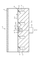
実施の形態1では、図12に示す浮上搬送システムの中の移送ユニット100として、図1に示す移送ユニットAを用いる。移送ユニットAは、基台1、囲い材2および帯電中和装置3を備えている。なお、囲い材2は、図13の囲い材120と同じであるので、囲い材2の説明を省略する。
【0034】
基台1は、その搬送面1Aの中心部を除いて、図14,15に示す噴出孔113,115および気体室114,116と同じ噴出孔11,13および気体室12をそれぞれ備えている。なお、噴出孔13用の気体室の図示は、省略されている。搬送面1Aの中心部には、帯電中和装置3が設置されている。実施の形態1では、噴出孔11は、浮上用の気体を噴出する。
【0035】
帯電中和装置3は、収納部31、UV(Ultraviolet radiation:紫外線)ランプ32および制御部33を備えている。実施の形態1では、溝部が収納部31であり、帯電中和部がUVランプ32と制御部33とで構成されている。
【0036】
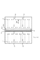
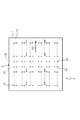
収納部31の第1収納部分31Aは、搬送面1Aの中央部に、かつ、図2に示すように、移動方向310に対して直角方向に設けられている、板状の溝である。第1収納部分31Aには、光を通す石英板31Bが、第1収納部分31Aに対して密着状態で、かつ、搬送面1Aに対して平らに取り付けられている。第1収納部分31Aの底には、第2収納部分31Cが、第1収納部分31Aに対して段差を形成するように設けられ、UVランプ32は、収納部31の第2収納部分31Cに収められている。UVランプ32は、石英板31Bに近接して、第2収納部31Cに収められる。電圧がUVランプ32に加えられると、UVランプ32は、紫外線を発光する。このとき、UVランプ32が石英板31Bに近接して第2収納部31Cに収められているので、紫外線の照射角度が大きく、紫外線は、搬送空間を広く照射する。この紫外線によって、石英板31Bが位置する、搬送面1Aの上にある搬送空間では、気体がイオン化されるので、石英板31Bの上面付近は、窒素のプラスイオンとマイナスイオンとを含む雰囲気となる。
【0037】
制御部33は、基台1の下側に設置されて、電線33Aによって、UVランプ32に接続されている。制御部33は、紫外線を発光させるための電圧を生成し、電線33Aを通して、この電圧をUVランプ32に加える。
【0038】
以上が、実施の形態1に係る移送ユニットAの構成である。次に、実施の形態1の動作について説明する。
【0039】
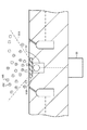
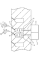
帯電中和装置3の制御部33がUVランプ32に電圧を加えると、図3に示すように、UVランプ32が紫外線32Aを出す。この紫外線32Aによって、石英板31B上面側に位置する気体がイオン化されて、プラスイオン401とマイナスイオン402とが発生する。この結果、石英板31B上面側の搬送空間は、運ばれてくるガラス板300を中和するために十分なプラスイオン401とマイナスイオン402とを含むものとなる。
【0040】
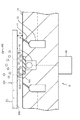
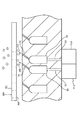
この状態のときに、図4に示すように、帯電されたガラス板300が移送ユニットAの搬送空間を通過すると、ガラス板300の下面302側のマイナスの静電荷が気体のプラスイオン401によって中和され、上面301側のプラスの静電荷が気体のマイナスイオン402によって中和される。特に、ガラス板300の下面302側では、約0.2〜0.5mmの浮上間隔dに存在する気体が、UVランプ32からの紫外線32Aによって確実にイオン化され、イオン化で発生したプラスイオンによって、ガラス板300の下面302のマイナス電荷を完全に中和することができる。また、イオン化で発生したマイナスイオンは、ガラス板300の下面302のマイナス電荷による斥力を受け、中和されずにガラス板300の上面301側に流れる。この結果、ガラス板300の上面301側にはプラスイオンが十分に存在するので、上面301の電荷を完全に中和することができる。
【0041】
こうして、実施の形態1によれば、帯電中和装置3のUVランプ32が搬送面1A側に配置されているので、ガラス板300の上面301および下面302の帯電を確実に中和することができる。
【0042】
また、第2収納部分31Cが石英板31Bによって密封されているので、第2収納部分31Cからの外気等が移送ユニットAの移送空間に入り込むことを防いで、外気等による影響を石英板31Bに与えることを防止することができる。同時に、石英板31Bによって、UVランプ32を保護することができる。
【0043】
[実施の形態2]
次に、本発明の実施の形態2について説明する。
【0044】
実施の形態2では、実施の形態1で用いられた帯電中和装置3が、図12に示す浮上搬送システムの中の制御ユニット200として用いられる、制御ユニットBに設置されている。つまり、図5に示すように、移送ユニットが接続されている側の搬送面4Aに設けられている。かつ、収納部31の長手方向が移動方向310と直角に交差するように、収納部31が設けられている。
【0045】
これによって、移動方向310に進んで、制御ユニットBの搬送空間に入るガラス板300、または、移動方向310と逆に進んで、制御ユニットBから出るガラス板300が、基台4の搬送面4Aに設けられている収納部31のUVランプ32上を通過するので、ガラス板300の帯電を完全に中和することができる。
【0046】
[実施の形態3]
次に、本発明の実施の形態3について説明する。
【0047】
実施の形態3では、プラスイオンとマイナスイオンとを発生させるために、次のようにしている。つまり、実施の形態1,2では、プラスイオンとマイナスイオンを発生させるために、紫外線を用いたが、実施の形態3では、紫外線の代わりに、透過性の小さい軟X線(Soft X-rays)を用いる。軟X線によれば、オゾンの発生を伴わないで、プラスイオンとマイナスイオンとの生成が可能である。また、軟X線の減衰が速いために、人体に対する照射を防ぐための遮蔽対策が容易である。
【0048】
このような軟X線を用いた帯電中和装置によっても、ガラス板300の帯電を完全に中和することができる。
【0049】
[実施の形態4]
次に、本発明の実施の形態4について説明する。
【0050】
実施の形態4では、図6に示すように、帯電中和装置3の代わりに、帯電中和装置5が、移送ユニットAの基台1の搬送面1Aに設置されている。帯電中和装置5は、図7に示すように、イオン生成器51A,51B、絶縁供給管52、絶縁気体室53および絶縁噴出孔54を備えている。
【0051】
イオン生成器51Aは、細い金属電極(図示を省略)に高電圧を加えて、プラスイオンを発生する。また、イオン生成器51Bは、イオン生成器51Aとは異なる極性の高電圧を金属電極に加えて、マイナスイオンを発生する。イオン生成器51Aは、発生したプラスイオンを、絶縁供給管52を通して、絶縁気体室53に流し、イオン生成器51Bは、発生したマイナスイオンを、絶縁供給管52を通して、絶縁気体室53に流す。また、図8に示すように、絶縁供給管52、絶縁気体室53および絶縁噴出孔54の内壁52A,53A,54Aには、絶縁用の被膜が設けられている。絶縁噴出孔54は、基台1の搬送面1Aに設定された設置ライン5A,5B上にそれぞれ配置されている帯電中和孔である。設置ライン5A,5Bは、移動方向310と交差する方向に設定されている。各絶縁噴出孔54は、気体室53に通じ、図1の噴出孔11と同様に、絶縁気体室53からの気体を噴出する。
【0052】
絶縁気体室53は、図1の気体室12と同様に、気体の供給を受ける。同時に、設置ライン5Aに対応する絶縁気体室53には、イオン生成器51Aからのプラスイオンが絶縁供給管52を経て流れ込む。この結果、設置ライン5A上の絶縁噴出孔54は、プラスイオンを含んだ気体を噴出する。また、設置ライン5Bに対応する絶縁気体室53には、イオン生成器51Bからのマイナスイオンが絶縁供給管52を経て流れ込む。この結果、設置ライン5B上の絶縁噴出孔54は、マイナスイオンを含んだ気体を噴出する。
【0053】
実施の形態4によれば、図8に示すように、プラスイオン401が、設置ライン5A上の絶縁噴出孔53から噴出され、マイナスイオン402が、設置ライン5B上の絶縁噴出孔53から噴出される。この結果、絶縁噴出孔53の周囲の搬送空間は、ガラス板300の帯電を中和するために十分なプラスイオン401とマイナスイオン402とを含むものとなる。この状態のときに、図9に示すように、帯電されたガラス板300が移送ユニットAの搬送空間を通過すると、ガラス板300の上面301側のプラスの静電荷がマイナスイオン402によって中和され、下面302側のマイナスの静電荷がプラスイオン401によって中和される。特に、設置ライン5A上の絶縁噴出孔53からのプラスイオン401が、ガラス板300の下面302に直接当たるので、従来では、中和することができなかった下面302側の静電荷を除くことができる。
【0054】
また、帯電中和装置5がイオン生成器51からのプラスイオン401とマイナスイオン402とを、絶縁供給管52を経て絶縁気体室53に注入するだけの、簡単な構造であるので、移送ユニットAの大幅な変更を不要にして、帯電を完全に中和することを可能にする。
【0055】
[実施の形態5]
次に、本発明の実施の形態5について説明する。
【0056】
実施の形態5では、実施の形態4で用いられた帯電中和装置5が制御ユニットBに設置されている。つまり、図10に示すように、移送ユニットが接続されている側の搬送面4Aに、設置ライン5A,5Bが設けられている。かつ、設置ライン5A,5Bは、移動方向310と直角に交差するように配置されている。
【0057】
これによって、移動方向310に進んで、制御ユニットBの搬送空間に入るガラス板300、または、移動方向310と逆に進んで、制御ユニットBの搬送空間から出るガラス板300が、設定ライン5A,5Bに配置されている噴出孔54上を通過するので、ガラス板300の帯電を完全に中和することができる。
【0058】
[実施の形態6]
次に、本発明の実施の形態6について説明する。
【0059】
実施の形態6では、実施の形態4で用いられた帯電中和装置5が制御ユニットBに設置されている。つまり、図11に示すように、制御ユニットBの搬送面4Aに設定されている設定ライン223に配置されている絶縁噴出孔261、および、外側の設定ライン224に配置されている絶縁噴出孔262が、プラスイオンとマイナスイオンとをそれぞれ噴出する絶縁噴出孔54として用いられている。
【0060】
これによって、移動方向310から制御ユニットBに移動するガラス板300の中心が、噴出孔214と絶縁噴出孔261,262とから噴射される気体によって、中心の吸引孔213に移動される。同時に、ガラス板300の裏面には、絶縁噴出孔261からのプラスイオンと絶縁噴出孔262からのマイナスイオンとが直接噴射される。この結果、従来では、中和することができなかった、ガラス板300の裏面側の静電荷を除くことができる。
【0061】
[実施の形態7]
次に、本発明の実施の形態7について説明する。
【0062】
実施の形態7では、気体を供給する供給系とは、通じていない気体室を用いる。つまり、実施の形態4〜6では、イオン生成器が気体の供給系と通じている気体室にイオンを供給したが、実施の形態7では、送風機能を持つイオン生成器が用いられる。これによって、イオン生成器と供給系とを分離することができる。
【0063】
以上、実施の形態1〜実施の形態7について説明したが、本発明は、これらの実施の形態に限定されることはない。例えば、実施の形態1〜実施の形態7では、補助的な帯電中和手段として、従来の帯電中和器230を併用することが可能である。
【0064】
また、噴出孔11から噴出する気体として、高純度乾燥空気、高純度窒素ガス、高純度アルゴンガス、高純度炭酸ガス等を用いることが可能である。ウエハを気流搬送する場合には、搬送用のガスとして、不純物濃度が数ppb以下の高純度窒素ガスを用いるのが最適である。
【0065】
また、浮上搬送システムとして、TFT型液晶ディスプレイ用のガラス板等を気流搬送するものを例としたが、本発明は、ガラス板に限られることなく、各種板状基体を搬送するシステムに適用可能である。
【0066】
さらに、移送ユニットと制御ユニットとに設けられた噴出孔の配列方式としては、各種のものがあるが、本発明は、これら各種の配列方式にも適用が可能である。
【0067】
【発明の効果】
以上、説明したように、本発明によれば、搬送面に設けられた溝部と、この溝部内に設けられると共に、気体をイオン化する電磁波を溝部から、搬送面上の搬送空間に向けて出力する帯電中和部とを設けた。また、電磁波が紫外線または軟X線である。この結果、搬送面と板状基体の下面との狭い空間にある気体が溝部から照射される紫外線などの電磁波によって、確実にイオン化されるので、板状基体の下面の帯電を完全に中和することができる。同時に、板状基体の上面側には、電磁波の照射によるイオン化された気体が多量に存在するので、板状基体の上面の帯電も完全に中和することができる。
【0068】
本発明によれば、搬送面に設けられた少なくとも1つの帯電中和孔と、この帯電中和孔を介して、搬送面上の搬送空間に向けてイオンを噴出させる帯電中和部とを設けた。また、噴出孔にイオンを注入する帯電中和部を設けたので、搬送面の帯電中和孔や噴出孔からイオン化された気体が板状基体に向かって吹き付けられる。これによって、板状基体の下面の帯電を中和することができる。同時に、板状基体の上面側には、イオン化された気体の噴出による多量のイオン化された気体が存在するので、板状基体の上面の帯電をも完全に中和することができる。
【0069】
本発明によれば、浮上搬送装置用の帯電中和装置を移送ユニットに設けた。また、搬送装置用の帯電中和装置を制御ユニットに設けた。これによって、浮上搬送システムの任意の位置で板状基体の帯電を中和する。例えば、板状基体を処理する次の処理装置等の手前に位置する移送ユニットや制御ユニットに浮上搬送装置用の帯電中和装置を設置すると、板状基体の帯電が処理装置の直前で中和されるので、帯電による影響が次の処理で発生することを防ぐことができる。
【図面の簡単な説明】
【図1】実施の形態1に係わる移送ユニットの断面を示す断面図である。
【図2】上記移送ユニットの搬送面を示す平面図である。
【図3】実施の形態1の動作を説明するための説明図である。
【図4】実施の形態1の動作を説明するための説明図である。
【図5】実施の形態2に係る移送ユニットの搬送面を示す平面図である。
【図6】実施の形態4に係る移送ユニットの搬送面を示す平面図である。
【図7】上記移送ユニットの断面を示す断面図である。
【図8】実施の形態4の動作を説明するための説明図である。
【図9】実施の形態4の動作を説明するための説明図である。
【図10】実施の形態5に係る制御ユニットの搬送面を示す平面図である。
【図11】実施の形態6に係る制御ユニットの搬送面を示す平面図である。
【図12】従来の板状基体搬送システムを示す平面図である。
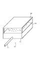
【図13】従来の移送ユニットを示す斜視図である。
【図14】図13のI−I断面図である。
【図15】図13のII−II断面図である。
【図16】従来の移送ユニットによる噴出方向を示す説明図である。
【図17】従来の制御ユニットを示す斜視図である。
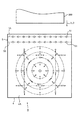
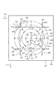
【図18】従来の移送ユニットによる噴出方向を示す説明図である。
【図19】従来の帯電中和器の設置の様子を示す断面図である。
【符号の説明】
A,100 移送ユニット
B,200 制御ユニット
1,4,110,210 基台
1A,4A,112,212 搬送面
2,120,220 囲い材
3,5 帯電中和装置
5A 設置ライン
11,41A,42A,113,115,215〜218,251〜253 噴出孔
12,114,116 気体室
31 収納部
31A 第1収納部分
31B 石英板
31C 第2収納部分
32 UVランプ
33 制御部
33A 電線
41,42,221〜226 設定ライン
45,213 吸引孔
51A,51B イオン生成器
52 絶縁供給管
52A,53A,54A 内壁
53 絶縁気体室
54,261,262 絶縁噴出孔
111,211 供給系
112A 中心
113A,115A,214A〜218A,251A〜253A 噴出方向
230 帯電中和器
300 ガラス板
301 上面
302 下面
310 移動方向
311 転換方向
401 プラスイオン
402 マイナスイオン[0001]
BACKGROUND OF THE INVENTION
In the present invention, when the plate-like substrate is floated by jetting a gas to the plate-like substrate, and the plate-like substrate is moved, stopped, stopped, and changed in this state, the plate hits the plate-like substrate by the gas hitting the plate-like substrate. BACKGROUND OF THE
[0002]
[Prior art]
As a system that floats and transports a plate-like substrate, for example, there is a system that transports a glass plate for a TFT type liquid crystal display. This transport system is shown in FIG. This transport system is configured by combining the
[0003]
The
[0004]
As shown in FIG. 14, the
[0005]
The gas supplied from the
[0006]
Thus, the
[0007]
The
[0008]
As shown in FIG. 18, a
[0009]
In the
[0010]
Further, an
[0011]
In the
[0012]
Further, the
[0013]
The
[0014]
When the
[0015]
By such an operation, the direction of the
[0016]
A processing system for the
[0017]
By the way, the
[0018]
In order to eliminate such charge caused by charging, there is a technique shown in International Application No. PCT / JP91 / 01469. According to this technique, a
[0019]
However, this charge removal technique has the following problems. That is, the
[0020]
Similarly, when the
[0021]
As described above, the conventional charge neutralization technology has the following problems. That is, when this plate-like substrate is transported by the floating of the plate-like substrate, the plate-like substrate floats only about 0.2 to 0.5 mm. For this reason, there is a problem in that the charge on the back surface of the plate-like substrate cannot be completely neutralized because the gas containing positive ions and negative ions is not sufficiently supplied to the back surface of the plate-like substrate.
[0022]
[Problems to be solved by the invention]
In the present invention, when the plate-like substrate is floated by jetting a gas to the plate-like substrate, and the plate-like substrate is moved, stopped, stopped, and changed in this state, the plate hits the plate-like substrate by the gas hitting the plate-like substrate. It is an object of the present invention to provide a charge neutralizing device and a levitating and conveying system for a levitation conveying device capable of completely neutralizing the charging of the plate-like substrate when the dying substrate is charged.
[0023]
[Means for Solving the Problems]
The charging neutralization device for a levitation conveyance device of the present invention is a levitation conveyance device provided in a levitation conveyance device that conveys a plate-like substrate in a state of being floated by a gas ejected from a plurality of ejection holes provided on a conveyance surface. Charge neutralizer for equipmentAnd
The transfer surfaceIs provided with a groove,
A charging neutralization unit that is provided in the groove and outputs an electromagnetic wave that ionizes the gas from the groove toward a conveyance space on the conveyance surface.ButEstablishmentIs,
SaidThe groove portion has a first storage portion and a second storage portion formed with a step at the bottom of the first storage portion, and a plate that allows light to pass through the first storage portion is attached flat to the conveyance surface. The electromagnetic wave source is stored in the second storage part..
[0024]
The levitation conveyance device injects gas onto the plate-like substrate, and the plate-like substrate floats slightly from the conveyance surface. At this time, since the gas is blown onto the plate-like substrate, the plate-like substrate is charged.
[0025]
According to the said structure, since electromagnetic waves are output from the groove part provided in the conveyance surface, the gas of the conveyance space on the conveyance surface irradiated with this electromagnetic wave is ionized. At this time, the gas existing in the narrow space between the transport surface and the plate-like substrate is reliably ionized by the electromagnetic wave irradiated from the groove, so that the charging of the lower surface of the plate-like substrate facing the transport surface is completely neutralized. Can be summed. Further, since there is a large amount of gas ionized by electromagnetic waves on the upper surface side of the plate-like substrate, the charge on the upper surface of the plate-like substrate can be completely neutralized.
[0026]
referenceThe charging neutralization device for a levitation conveyance device according to the present invention includes a plurality of ejection holes provided on a conveyance surface, and the levitation conveyance device conveys the plate-shaped substrate in a state of being levitated by gas ejected from the ejection holes. In the charging neutralization device for a levitation conveyance device provided in the above, at least one charge neutralization hole provided in the conveyance surface, and toward the conveyance space on the conveyance surface via the charge neutralization hole A charge neutralization section for ejecting ions is provided.
[0027]
Also,referenceThe charging neutralization device for a levitation conveyance device according to the present invention includes a plurality of ejection holes provided on a conveyance surface, and the levitation conveyance device conveys the plate-shaped substrate in a state of being levitated by gas ejected from the ejection holes. In the charge neutralization device for a levitation transport apparatus provided in the above, a charge neutralization section for injecting ions into the ejection holes is provided.
[0028]
According to the above configuration, since the ionized gas is blown toward the plate-like substrate from the charge neutralization hole or the ejection hole on the transport surface, the charge on the lower surface of the plate-like substrate can be neutralized. In addition, a large amount of ionized gas exists on the upper surface side due to the ejection of the ionized gas, and the charging of the upper surface of the plate-like substrate can be neutralized by this gas.
[0029]
The levitation conveyance system of the present invention includes a plurality of ejection holes provided on a conveyance surface, a transfer unit that moves linearly in a state in which a plate-like substrate is levitated by gas ejected from the ejection holes, and a conveyance Ascending in combination with a control unit that has a plurality of ejection holes provided on the surface, and that stops, stops, and changes direction when the plate-like substrate is levitated by the gas ejected from the ejection holes In the transport system, claims1The transfer unit is provided with a charge neutralization device for a floating transportation device.
[0030]
The levitation conveyance system of the present invention includes a plurality of ejection holes provided on a conveyance surface, a transfer unit that moves linearly in a state in which a plate-like substrate is levitated by gas ejected from the ejection holes, and a conveyance Ascending in combination with a control unit that has a plurality of ejection holes provided on the surface, and that stops, stops, and changes direction when the plate-like substrate is levitated by the gas ejected from the ejection holes In the transport system, claims1The control unit is provided with a charge neutralization device for a floating transportation device.
[0031]
According to the above configuration, the charge neutralization device for the levitation transport device is provided in the transfer unit and the control unit. At this time, for example, if a charge neutralizing device for a levitation transport device is installed in the transfer unit or control unit positioned in front of the next processing device for processing the plate-like substrate, the plate-like substrate is charged immediately before the processing device. Since it is neutralized, it is possible to prevent the influence of charging from occurring in the next processing apparatus or the like.
[0032]
DETAILED DESCRIPTION OF THE INVENTION
Hereinafter, embodiments of the present invention will be described in detail with reference to the drawings.
[0033]
[Embodiment 1]
In the first embodiment, the transfer unit A shown in FIG. 1 is used as the
[0034]
The
[0035]
The charging
[0036]
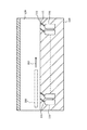
The
[0037]
The
[0038]
The above is the configuration of the transfer unit A according to the first embodiment. Next, the operation of the first embodiment will be described.
[0039]
When the
[0040]
In this state, as shown in FIG. 4, when the charged
[0041]
Thus, according to the first embodiment, since the
[0042]
In addition, since the
[0043]
[Embodiment 2]
Next, a second embodiment of the present invention will be described.
[0044]
In the second embodiment, the
[0045]
As a result, the
[0046]
[Embodiment 3]
Next, a third embodiment of the present invention will be described.
[0047]
In the third embodiment, the following is performed in order to generate positive ions and negative ions. That is, in the first and second embodiments, ultraviolet rays are used to generate positive ions and negative ions, but in the third embodiment, soft X-rays having a low transmittance are used instead of ultraviolet rays. ) Is used. According to soft X-rays, positive ions and negative ions can be generated without generating ozone. In addition, since soft X-ray attenuation is fast, it is easy to take shielding measures to prevent irradiation of the human body.
[0048]
The charging of the
[0049]
[Embodiment 4]
Next, a fourth embodiment of the present invention will be described.
[0050]
In the fourth embodiment, as shown in FIG. 6, instead of the
[0051]
The
[0052]
The insulating
[0053]
According to the fourth embodiment, as shown in FIG. 8,
[0054]
Further, since the charging
[0055]
[Embodiment 5]
Next, a fifth embodiment of the present invention will be described.
[0056]
In the fifth embodiment, the
[0057]
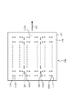
As a result, the
[0058]
[Embodiment 6]
Next, a sixth embodiment of the present invention will be described.
[0059]
In the sixth embodiment, the
[0060]
Accordingly, the center of the
[0061]
[Embodiment 7]
Next, a seventh embodiment of the present invention will be described.
[0062]
In the seventh embodiment, a gas chamber that does not communicate with a supply system that supplies gas is used. That is, in
[0063]
The first to seventh embodiments have been described above, but the present invention is not limited to these embodiments. For example, in the first to seventh embodiments, a
[0064]
Further, as the gas ejected from the
[0065]
In addition, as an example of the levitation conveyance system, a glass plate for a TFT type liquid crystal display is conveyed as an example. However, the present invention is not limited to the glass plate, and can be applied to a system for conveying various plate-like substrates. It is.
[0066]
Furthermore, there are various types of arrangement methods of the ejection holes provided in the transfer unit and the control unit, but the present invention can also be applied to these various arrangement methods.
[0067]
【The invention's effect】
As described above, according to the present invention, the groove provided on the conveyance surface and the electromagnetic wave that ionizes the gas are output from the groove toward the conveyance space on the conveyance surface. A charging neutralization part was provided. The electromagnetic waves are ultraviolet rays or soft X-rays. As a result, the gas in the narrow space between the conveying surface and the lower surface of the plate-like substrate is reliably ionized by electromagnetic waves such as ultraviolet rays irradiated from the groove, so that the charging of the lower surface of the plate-like substrate is completely neutralized. be able to. At the same time, since a large amount of gas ionized by the irradiation of electromagnetic waves exists on the upper surface side of the plate-like substrate, the charge on the upper surface of the plate-like substrate can be completely neutralized.
[0068]
According to the present invention, there is provided at least one charge neutralization hole provided on the transfer surface, and a charge neutralization portion for ejecting ions toward the transfer space on the transfer surface via the charge neutralization hole. It was. Moreover, since the charge neutralization part which inject | pours ion into a jet hole is provided, the gas ionized from the charge neutralization hole and jet hole of a conveyance surface is sprayed toward a plate-shaped base | substrate. Thereby, the charging of the lower surface of the plate-like substrate can be neutralized. At the same time, since a large amount of ionized gas is present on the upper surface side of the plate-like substrate, the charge on the upper surface of the plate-like substrate can be completely neutralized.
[0069]
According to the present invention, the transfer unit is provided with a charge neutralization device for the levitation transport device. In addition, a charge neutralization device for the transfer device was provided in the control unit. This neutralizes the charging of the plate-like substrate at an arbitrary position of the levitation conveyance system. For example, if a charge neutralization device for a levitation transport device is installed in the transfer unit or control unit located in front of the next processing device or the like for processing a plate-like substrate, the charge of the plate-like substrate is neutralized immediately before the treatment device. Therefore, the influence of charging can be prevented from occurring in the next processing.
[Brief description of the drawings]
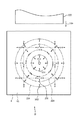
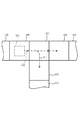
FIG. 1 is a cross-sectional view showing a cross section of a transfer unit according to
FIG. 2 is a plan view showing a transfer surface of the transfer unit.
FIG. 3 is an explanatory diagram for explaining the operation of the first embodiment.
FIG. 4 is an explanatory diagram for explaining the operation of the first embodiment;
5 is a plan view showing a transport surface of a transfer unit according to
6 is a plan view showing a transport surface of a transfer unit according to
FIG. 7 is a cross-sectional view showing a cross section of the transfer unit.
FIG. 8 is an explanatory diagram for explaining the operation of the fourth embodiment.
FIG. 9 is an explanatory diagram for explaining the operation of the fourth embodiment.
FIG. 10 is a plan view showing a conveyance surface of a control unit according to a fifth embodiment.
FIG. 11 is a plan view showing a conveyance surface of a control unit according to a sixth embodiment.
FIG. 12 is a plan view showing a conventional plate-like substrate transport system.
FIG. 13 is a perspective view showing a conventional transfer unit.
14 is a cross-sectional view taken along the line II of FIG.
15 is a cross-sectional view taken along the line II-II in FIG.
FIG. 16 is an explanatory view showing a jetting direction by a conventional transfer unit.
FIG. 17 is a perspective view showing a conventional control unit.
FIG. 18 is an explanatory diagram showing the ejection direction by a conventional transfer unit.
FIG. 19 is a cross-sectional view showing a state of installation of a conventional charge neutralizer.
[Explanation of symbols]
A, 100 transfer unit
B, 200 Control unit
1,4,110,210 base
1A, 4A, 112, 212 Conveying surface
2,120,220 Enclosure
3,5 Charge neutralizer
5A installation line
11, 41A, 42A, 113, 115, 215 to 218, 251 to 253
12, 114, 116 Gas chamber
31 Storage section
31A First storage part
31B Quartz plate
31C Second storage part
32 UV lamp
33 Control unit
33A electric wire
41, 42, 221-226 setting line
45,213 Suction hole
51A, 51B ion generator
52 Insulated supply pipe
52A, 53A, 54A inner wall
53 Insulating gas chamber
54, 261, 262 Insulation outlet
111, 211 supply system
112A center
113A, 115A, 214A to 218A, 251A to 253A ejection direction
230 Charge neutralizer
300 glass plate
301 Upper surface
302 Bottom
310 Movement direction
311 Direction of change
401 positive ion
402 Negative ion
Claims (6)
前記搬送面に溝部が設けられ、
この溝部内に設けられると共に、前記気体をイオン化する電磁波を前記溝部から、前記搬送面上の搬送空間に向けて出力する帯電中和部が設けられ、
前記溝部は、第1収納部分と、第1収納部分の底に、段差をもって形成された第2収納部分とを有し、第一収納部分に光を通す板を搬送面に対して平らに取り付けられ、電磁波源が第2収納部分に収納されている浮上搬送装置用の帯電中和装置。A charging neutralization device for a levitation conveyance device provided in a levitation conveyance device that conveys a plate-like substrate in a state of being levitated by a gas ejected from a plurality of ejection holes provided on a conveyance surface ,
A groove is provided on the transport surface,
Together provided the groove, the electromagnetic ionizing said gas from said groove, charging neutralization unit is provided for output to the transfer space on the conveying surface,
The groove portion has a first storage portion and a second storage portion formed with a step at the bottom of the first storage portion, and a plate that allows light to pass through the first storage portion is attached flat to the transport surface. And a neutralizing device for a levitating and conveying apparatus in which the electromagnetic wave source is accommodated in the second accommodating portion .
Priority Applications (3)
| Application Number | Priority Date | Filing Date | Title |
|---|---|---|---|
| JP23094398A JP4132000B2 (en) | 1998-08-17 | 1998-08-17 | Charge neutralization device and levitation conveyance system for levitation conveyance device |
| TW088113943A TW419710B (en) | 1998-08-17 | 1999-08-16 | Electrification neutralizing device for floating conveyance apparatus and floating conveyance system |
| PCT/JP1999/004416 WO2000009429A1 (en) | 1998-08-17 | 1999-08-17 | Charging neutralizer for floating transportation device and floating transportation system |
Applications Claiming Priority (1)
| Application Number | Priority Date | Filing Date | Title |
|---|---|---|---|
| JP23094398A JP4132000B2 (en) | 1998-08-17 | 1998-08-17 | Charge neutralization device and levitation conveyance system for levitation conveyance device |
Related Child Applications (1)
| Application Number | Title | Priority Date | Filing Date |
|---|---|---|---|
| JP2008060264A Division JP2008179484A (en) | 2008-03-10 | 2008-03-10 | Electrostatic charge neutralization device for floating carrying device and floating carrying system |
Publications (2)
| Publication Number | Publication Date |
|---|---|
| JP2000062953A JP2000062953A (en) | 2000-02-29 |
| JP4132000B2 true JP4132000B2 (en) | 2008-08-13 |
Family
ID=16915748
Family Applications (1)
| Application Number | Title | Priority Date | Filing Date |
|---|---|---|---|
| JP23094398A Expired - Fee Related JP4132000B2 (en) | 1998-08-17 | 1998-08-17 | Charge neutralization device and levitation conveyance system for levitation conveyance device |
Country Status (3)
| Country | Link |
|---|---|
| JP (1) | JP4132000B2 (en) |
| TW (1) | TW419710B (en) |
| WO (1) | WO2000009429A1 (en) |
Families Citing this family (4)
| Publication number | Priority date | Publication date | Assignee | Title |
|---|---|---|---|---|
| JP4543794B2 (en) * | 2004-07-09 | 2010-09-15 | 国立大学法人東北大学 | Flat member conveying device |
| JP4396847B2 (en) | 2004-12-22 | 2010-01-13 | Smc株式会社 | Air levitation device with static eliminator and method of static eliminator in the levitation device |
| KR101205832B1 (en) * | 2009-11-27 | 2012-11-29 | 세메스 주식회사 | Substrate transferring unit and method of transfering substrate using the same |
| JP5549885B2 (en) * | 2011-04-08 | 2014-07-16 | 株式会社ダイフク | Plate-type substrate transport device |
Family Cites Families (4)
| Publication number | Priority date | Publication date | Assignee | Title |
|---|---|---|---|---|
| JPS5733002Y2 (en) * | 1979-05-11 | 1982-07-21 | ||
| JP3162144B2 (en) * | 1990-11-16 | 2001-04-25 | 株式会社渡邊商行 | Sheet-like substrate transfer device |
| JP3414836B2 (en) * | 1994-05-23 | 2003-06-09 | 大日本スクリーン製造株式会社 | Substrate transfer device and substrate transfer method |
| JPH088319A (en) * | 1994-06-16 | 1996-01-12 | Sony Corp | Substrate transfer mechanism, substrate transfer device, and semiconductor manufacturing device |
-
1998
- 1998-08-17 JP JP23094398A patent/JP4132000B2/en not_active Expired - Fee Related
-
1999
- 1999-08-16 TW TW088113943A patent/TW419710B/en not_active IP Right Cessation
- 1999-08-17 WO PCT/JP1999/004416 patent/WO2000009429A1/en not_active Ceased
Also Published As
| Publication number | Publication date |
|---|---|
| WO2000009429A1 (en) | 2000-02-24 |
| TW419710B (en) | 2001-01-21 |
| JP2000062953A (en) | 2000-02-29 |
Similar Documents
| Publication | Publication Date | Title |
|---|---|---|
| KR100912981B1 (en) | Ionization Airflow Release Type Dust-Free Ionizer | |
| KR100980280B1 (en) | Antistatic conveying device and antistatic method at conveyance | |
| WO1992009103A1 (en) | Device and method for carrying thin plate-like substrate | |
| KR101622320B1 (en) | Apparatus for providing ion beam and system for removing static electricity in high vacuum including the apparatus | |
| JP4132000B2 (en) | Charge neutralization device and levitation conveyance system for levitation conveyance device | |
| US20090258507A1 (en) | Substrate Treatment Device and Substrate Treatment Method | |
| TWI724316B (en) | Flat panel display manufacturing device | |
| JP2005072374A (en) | Substrate-treating device | |
| JP3162144B2 (en) | Sheet-like substrate transfer device | |
| JP2008179484A (en) | Electrostatic charge neutralization device for floating carrying device and floating carrying system | |
| JP4409641B2 (en) | Air ionization apparatus and method | |
| JP5047765B2 (en) | Charged ion transport ionizer using ion nucleus condensation by adiabatic expansion | |
| JP4230583B2 (en) | Charged particle transport ionization apparatus and method | |
| JP2000068093A (en) | Method and device for static elimination | |
| JP4543794B2 (en) | Flat member conveying device | |
| JP3049542B2 (en) | How to adjust the mixing ratio of positive and negative ions | |
| JP2005166787A (en) | Conveying apparatus and conveying method | |
| JP2004220872A (en) | Dust-free discharging and dust-removing system | |
| JP5008121B2 (en) | Charged ion transport ionizer using ion nucleus condensation | |
| JP2012094724A (en) | Static and dust elimination device | |
| JP2006216453A (en) | Charged object static eliminator and method | |
| JP2007194453A (en) | Electricity removing system in non-contact sheet-conveyance | |
| JPH07161485A (en) | Method and device for destaticizing charged object | |
| KR20080107150A (en) | Substrate Processing Equipment | |
| JP6808395B2 (en) | Board processing equipment |
Legal Events
| Date | Code | Title | Description |
|---|---|---|---|
| A621 | Written request for application examination |
Free format text: JAPANESE INTERMEDIATE CODE: A621 Effective date: 20050609 |
|
| A711 | Notification of change in applicant |
Free format text: JAPANESE INTERMEDIATE CODE: A711 Effective date: 20051102 |
|
| A521 | Request for written amendment filed |
Free format text: JAPANESE INTERMEDIATE CODE: A821 Effective date: 20051102 |
|
| A131 | Notification of reasons for refusal |
Free format text: JAPANESE INTERMEDIATE CODE: A131 Effective date: 20070502 |
|
| A521 | Request for written amendment filed |
Free format text: JAPANESE INTERMEDIATE CODE: A523 Effective date: 20070702 |
|
| A02 | Decision of refusal |
Free format text: JAPANESE INTERMEDIATE CODE: A02 Effective date: 20080109 |
|
| A521 | Request for written amendment filed |
Free format text: JAPANESE INTERMEDIATE CODE: A523 Effective date: 20080310 |
|
| A911 | Transfer to examiner for re-examination before appeal (zenchi) |
Free format text: JAPANESE INTERMEDIATE CODE: A911 Effective date: 20080317 |
|
| TRDD | Decision of grant or rejection written | ||
| A01 | Written decision to grant a patent or to grant a registration (utility model) |
Free format text: JAPANESE INTERMEDIATE CODE: A01 Effective date: 20080430 |
|
| A01 | Written decision to grant a patent or to grant a registration (utility model) |
Free format text: JAPANESE INTERMEDIATE CODE: A01 |
|
| A61 | First payment of annual fees (during grant procedure) |
Free format text: JAPANESE INTERMEDIATE CODE: A61 Effective date: 20080530 |
|
| FPAY | Renewal fee payment (event date is renewal date of database) |
Free format text: PAYMENT UNTIL: 20110606 Year of fee payment: 3 |
|
| R150 | Certificate of patent or registration of utility model |
Free format text: JAPANESE INTERMEDIATE CODE: R150 |
|
| FPAY | Renewal fee payment (event date is renewal date of database) |
Free format text: PAYMENT UNTIL: 20130606 Year of fee payment: 5 |
|
| LAPS | Cancellation because of no payment of annual fees |