JP4132392B2 - Building unit and unit building - Google Patents
Building unit and unit building Download PDFInfo
- Publication number
- JP4132392B2 JP4132392B2 JP12220199A JP12220199A JP4132392B2 JP 4132392 B2 JP4132392 B2 JP 4132392B2 JP 12220199 A JP12220199 A JP 12220199A JP 12220199 A JP12220199 A JP 12220199A JP 4132392 B2 JP4132392 B2 JP 4132392B2
- Authority
- JP
- Japan
- Prior art keywords
- building
- unit
- building unit
- floor beam
- floor
- Prior art date
- Legal status (The legal status is an assumption and is not a legal conclusion. Google has not performed a legal analysis and makes no representation as to the accuracy of the status listed.)
- Expired - Lifetime
Links
Images


Landscapes
- Joining Of Building Structures In Genera (AREA)
- Residential Or Office Buildings (AREA)
Description
【0001】
【発明の属する技術分野】
本発明は、建物ユニットとユニット建物に関する。
【0002】
【従来の技術】
従来、車庫又は玄関等のための建物ユニットとして、特開平8-68222号公報に記載の如く、各4本の柱と床梁と天井梁を骨組構成材(水平力と垂直力を負担して骨組を形成する構造材)とした箱形建物ユニットにおいて、1本の床梁もしくは相対する2本の床梁の中間部を切除し、床梁レベル以下に設けたたたきを床梁により遮ることなく外方床面(車庫導入路や玄関ステップ)に連続させ得るようにしたものがある。
【0003】
【発明が解決しようとする課題】
然しながら、従来技術では、建物ユニットの骨組構成材として柱と床梁の他に天井梁も必要であり、部材点数が多く、組立工数も多くなり、コスト高となる。
【0004】
また、建物ユニットの天井部に梁せいのある天井梁を備えるものであるため、車庫や玄関の天井高を大きくとることができない。
【0005】
本発明の課題は、車庫や玄関等に用いることのできる建物ユニットにおいて、構成簡素とし、天井高も大きくとることにある。
【0006】
【課題を解決するための手段】
請求項1に記載の本発明に係る建物ユニットは、柱と床梁を骨組構成材として備え、骨組構成材としての天井梁を備えず、且つ、床梁を1本だけ備え、この床梁の両端部のそれぞれに柱を接合してなるようにしたものである。
【0007】
【0008】
請求項2に記載の本発明は、請求項1に記載の建物ユニットを2個用い、それら2個の建物ユニットを向かい合せて離隔配置してなるようにしたユニット建物である。
【0009】
【0010】
【0011】
【0012】
【作用】
請求項1、2の本発明によれば下記(a)、(b)の作用がある。
(a)床梁を1本だけ備え、この床梁の両端部のそれぞれに柱を接合してなる建物ユニットを2個用い、それら2個の建物ユニットを向かい合せて離隔配置した。従って、2個の建物ユニットに挟まれる床面にそれらの床梁レベル以下に設けたたたきを、床梁により遮ることなく外方床面に連続させることができ、車庫や玄関を簡易に構築できる。
【0013】
(b)建物ユニットの天井部に骨組構成材としての天井梁を備えないから、部材点数を低減し、組立工数も低減でき、コスト低減できる。また、天井高を大きくとることができる。
【0014】
【0015】
【発明の実施の形態】
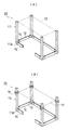
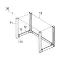
図1は第1参考形態の建物ユニットを示し、(A)は天井パネルを備えた斜視図、(B)は水平中間構面を備えた斜視図、図2は第2参考形態の建物ユニットを示す斜視図、図3は第3参考形態を示し、(A)は建物ユニットを示す斜視図、(B)はユニット建物を示す斜視図、図4は本発明実施形態を示し、(A)は建物ユニットを示す斜視図、(B)はユニット建物を示す斜視図、図5は第4参考形態を示し、(A)はユニット建物を示す斜視図、(B)は玄関を示す斜視図、(C)は玄関を示す正面図、図6は第5参考形態のユニット建物を示す斜視図、図7は第6参考形態のユニット建物を示す斜視図、図8は標準建物ユニット建物の一例を示す斜視図、図9は標準建物ユニットの他の例を示す側面図である。
【0016】
本発明が適用されるユニット建物は、例えば図8に示す如くの標準建物ユニット10を用いるとともに、本発明実施形態の建物ユニット50を用いて構成され、それら建物ユニット10、50を水平方向、鉛直方向に接合して構築される。
【0017】
標準建物ユニット10は、図8に示す如く、角鋼管等からなる柱11とリップ付C形鋼等からなる床梁12を骨組構成材として備え、骨組構成材としての天井梁は備えない。具体的には、標準建物ユニット10は、4個のコーナー部のそれぞれに配置される柱11の下端部にジョイントピース11Aを備え、このジョイントピース11Aに床梁12の端部を重ね合せ又は突き合せて接合した、箱形骨組構造体であり、柱11の上端部に天井パネル13を支持する。
【0018】
(第1参考形態)(図1)
建物ユニット20は、図1に示す如く、図8の標準建物ユニット10において4本の床梁12を枠組してなる床梁フレーム14の1本の床梁12の中間部を切除し、この切除梁の残存部を小梁15、15として備えるものである。建物ユニット20は床梁12、小梁15を基礎に設けたアンカーボルトに接合して据付けられる。
【0019】
建物ユニット20は、図1(A)に示す如く、4本の柱11の上端部に天井パネル13を支持することができる。
【0020】
また、建物ユニット20は、図1(B)に示す如く、4本の柱11の中間部に嵌合固定した外ダイヤフラム16に水平中間構面17を支持し、水平中間構面17の上部を物品収納空間等として使用できる。
【0021】
そして、建物ユニット20が用いられて構築されるユニット建物では、この建物ユニット20の床梁12の梁切除部12Aを出入口部とする車庫又は玄関等を形成できる。また、小梁15間の切除部には輸送時に脱着可能な仮梁を設けて用いる。
【0022】
従って、第1参考形態によれば以下の作用がある。
(a)床梁12を切除したことにより、床梁12レベル以下に設けたたたきを床梁12により遮ることなく外方床面に連続させることができ、車庫や玄関を簡易に構築できる。
【0023】
(b)建物ユニット20の天井部に骨組構成材としての天井梁を備えないから、部材点数を低減し、組立工数も低減でき、コスト低減できる。また、天井高を大きくとることができる。
【0024】
(c)床梁12の中間部の一部だけを切除し、梁切除部12Aに小梁15を備えたから、この小梁15に直交する柱11と床梁12を含む壁面に作用する水平力を、小梁15により支持し、建物ユニット20の耐力を向上できる。
【0025】
(第2参考形態)(図2)
建物ユニット30は、図2に示す如く、図8の標準建物ユニット10において4本の床梁12を枠組してなる床梁フレーム14の1本の床梁12の全部を切除したもの(建物ユニット20において、小梁15を撤去したもの)である。
【0026】
建物ユニット30は、建物ユニット20におけると同様に、4本の柱11の上端部に天井パネル13を支持し、又は4本の柱11の中間部に水平中間構面17を支持できる。
【0027】
そして、建物ユニット30が用いられて構築されるユニット建物でも、この建物ユニット30の床梁12の梁切除部12Aを出入口部とする車庫又は玄関等を形成できる。
【0028】
第2参考形態によれば、床梁12の全部を切除して小梁15を突出させないものとしたから、車庫又は玄関等において、出入口部の間口を左右の柱11、11の間隔にまで拡大できる。
【0029】
(第3参考形態)(図3)
建物ユニット40は、図3に示す如く、標準建物ユニット10におけると同様の柱11と床梁12を骨組構成材として備え、骨組構成材としての天井梁は備えない。建物ユニット40は、床梁12を1本だけ備え、この床梁12の両端部のそれぞれに柱11を接合し、更に、床梁12の両端部のそれぞれに該床梁12と柱11のそれぞれに直交する小梁15を接合した。尚、柱11は下端部にジョイントピース11Aを備え、床梁12、小梁15の端部をこのジョイントピース11Aに重ね合せ又は突き合せ接合してある。建物ユニット40は床梁12、小梁15を基礎に設けたアンカーボルトに接合して据付けられる。
【0030】
建物ユニット40が用いられて構築されるユニット建物では、図3(B)に示す如く、2個の建物ユニット40を用い、それら2個の建物ユニット40を向かい合せて離隔配置し、両建物ユニット40の小梁15、15に挟まれる部分を出入口部とする車庫又は玄関等を形成できる。尚、2個の建物ユニット40は、それらの全4本の柱11の上端部に天井パネル13を支持し、又は全4本の柱11の中間部に水平中間構面17を支持できる。
【0031】
従って、第3参考形態によれば以下の作用がある。
(a)床梁12を1本だけ備え、この床梁12の両端部のそれぞれに柱11を接合してなる建物ユニット40を2個用い、それら2個の建物ユニット40を向かい合せて離隔配置した。従って、2個の建物ユニット40に挟まれる床面にそれらの床梁12レベル以下に設けたたたきを、床梁12により遮ることなく外方床面に連続させることができ、車庫や玄関を簡易に構築できる。
【0032】
(b)上述(a)の建物ユニット40を構成する床梁12に、該床梁12と柱11のそれぞれに直交する小梁15を設けた。従って、床梁12と柱11を含む平面に作用する水平力を小梁15により支持可能とし、建物ユニット40の耐力を向上できる。
【0033】
(c)建物ユニット40の天井部に骨組構成材としての天井梁を備えないから、部材点数を低減し、組立工数も低減でき、コスト低減できる。また、天井高を大きくとることができる。
【0034】
尚、建物ユニット40にあっては、天井パネル13を現地取付けとすることにより、輸送効率を向上できる。
【0035】
(本発明実施形態)(図4)
建物ユニット50は、図4に示す如く、図3の建物ユニット40において、小梁15を撤去したものであり、柱11の下端部(及び床梁12)を基礎に剛接合して立設される。
【0036】
そして、建物ユニット50が用いられて構築されるユニット建物でも、図4に(B)に示す如く、2個の建物ユニット50を用い、それら2個の建物ユニット50を向かい合せて離隔配置し、両建物ユニット50の柱11、11に挟まれる部分を出入口部とする車庫又は玄関等を形成できる。尚、2個の建物ユニット50も、それら全4本の柱11の上端部に天井パネル13を支持し、又は全4本の柱11の中間部に水平中間構面17を支持できる。
【0037】
本発明実施形態によれば、建物ユニット50が小梁15を備えないものとしたから、車庫又は玄関等において、出入口部の間口を左右の柱11、11の間隔にまで拡大できる。
【0038】
(第4参考形態)(図5)
第4参考形態は、標準建物ユニット10と2個の建物ユニット40、40を用いてユニット建物の引込玄関60を構築したものである。基礎61と玄関ステップ62を設置し、玄関ステップ62を挟む両側の基礎61のそれぞれに建物ユニット40を据付け、玄関ステップ62の正面の基礎61に標準建物ユニット10を据付けることにより、両建物ユニット40、40に挟まれる部分を引込玄関60の引込空間とすることができる。
【0039】
尚、建物ユニット50にあっては、天井パネル13を現地取付けとすることにより、輸送効率を向上できる。
【0040】
(第5参考形態)(図6)
第5参考形態は、建物ユニット20と2個の建物ユニット40、40を用いてユニット建物の店舗70(又は車庫、引込玄関等)を構築したものである。
【0041】
(第6参考形態)(図7)
第6参考形態は、複数の建物ユニット30を並置し、複数の車庫80を構築したものである。
【0042】
以上、本発明の実施の形態を図面により詳述したが、本発明の具体的な構成はこの実施の形態に限られるものではなく、本発明の要旨を逸脱しない範囲の設計の変更等があっても本発明に含まれる。例えば、本発明が適用されるユニット建物では、標準建物ユニット10として図9に示すものを採用できる。図9の標準建物ユニット10は、柱91と床梁92とを接合した骨組構造体からなるものであり、4本の床梁92を矩形状に枠組してなる床梁フレーム93のコーナー部である柱接合部に外ダイヤラム94を溶接し、各外ダイヤフラム94に柱91を挿入し、柱91の任意の高さ位置に外ダイヤフラム94を溶接し、天井梁を有さずに構成したものである。そして、本発明の建物ユニット20、30、40、50においても、柱11と床梁12の接合構造として、床梁12の端部に設けた外ダイヤフラムに柱11を挿入固定するものを採用できる。
【0043】
【発明の効果】
以上のように本発明によれば、車庫や玄関等に用いることのできる建物ユニットにおいて、構成簡素とし、天井高も大きくとるができる。
【図面の簡単な説明】
【図1】 図1は第1参考形態の建物ユニットを示し、(A)は天井パネルを備えた斜視図、(B)は水平中間構面を備えた斜視図である。
【図2】 図2は第2参考形態の建物ユニットを示す斜視図である。
【図3】 図3は第3参考形態を示し、(A)は建物ユニットを示す斜視図、(B)はユニット建物を示す斜視図である。
【図4】 図4は本発明実施形態を示し、(A)は建物ユニットを示す斜視図、(B)はユニット建物を示す斜視図である。
【図5】 図5は第4参考形態を示し、(A)はユニット建物を示す斜視図、(B)は玄関を示す斜視図、(C)は玄関を示す正面図である。
【図6】 図6は第5参考形態のユニット建物を示す斜視図である。
【図7】 図7は第6参考形態のユニット建物を示す斜視図である。
【図8】 図8は標準建物ユニット建物の一例を示す斜視図である。
【図9】 図9は標準建物ユニットの他の例を示す側面図である。
【符号の説明】
20、30、40、50 建物ユニット
11 柱
12 床梁[0001]
BACKGROUND OF THE INVENTION
The present invention relates to a building unit and a unit building.
[0002]
[Prior art]
Conventionally, as a building unit for a garage or an entrance, etc., as described in JP-A-8-68222, each of four columns, a floor beam and a ceiling beam is composed of a framework component (bearing horizontal and vertical forces). In a box-type building unit that is a structural material that forms a frame), one floor beam or the middle part of two opposite floor beams is cut out, and the striking provided below the floor beam level is not blocked by the floor beams Some are designed to be continuous with the outside floor (garage introduction path or entrance step).
[0003]
[Problems to be solved by the invention]
However, in the prior art, a ceiling beam is required in addition to a column and a floor beam as a framework constituent material of a building unit, and the number of members is increased, the number of assembly steps is increased, and the cost is increased.
[0004]
In addition, since the ceiling of the building unit is provided with a ceiling beam with a beam, the ceiling height of the garage or the entrance cannot be increased.
[0005]
An object of the present invention is to simplify the configuration and increase the ceiling height in a building unit that can be used for a garage, a front door, or the like.
[0006]
[Means for Solving the Problems]
The building unit according to the first aspect of the present invention includes a column and a floor beam as a frame component, does not include a ceiling beam as a frame component, and includes only one floor beam. Columns are joined to both ends.
[0007]
[0008]
The present invention according to claim 2 is a unit building in which two building units according to claim 1 are used, and the two building units are arranged facing each other.
[0009]
[0010]
[0011]
[0012]
[Action]
The present invention according to claims 1 and 2 has the following actions (a) and (b).
(a) A single floor beam is provided, and two building units each having a column joined to each end of the floor beam are used, and the two building units are arranged facing each other. Therefore, striking provided below the floor beam level on the floor surface sandwiched between two building units can be continued to the outer floor surface without being blocked by the floor beam, and a garage or entrance can be easily constructed. .
[0013]
(b) Since the ceiling of the building unit is not provided with a ceiling beam as a frame component, the number of members can be reduced, the number of assembly steps can be reduced, and the cost can be reduced. Also, the ceiling height can be increased.
[0014]
[0015]
DETAILED DESCRIPTION OF THE INVENTION
FIG. 1 shows a building unit of a first reference form, (A) is a perspective view with a ceiling panel, (B) is a perspective view with a horizontal intermediate construction surface, and FIG. 2 is a building unit of a second reference form. FIG. 3 shows a third reference embodiment, (A) is a perspective view showing a building unit, (B) is a perspective view showing a unit building, FIG. 4 shows an embodiment of the present invention , (A) is perspective view of the building unit, (B) a perspective view showing a unit building 5 shows a fourth reference embodiment, (a) is a perspective view showing a unit building (B) is a perspective view showing the front door, ( C) is a front view showing the entrance, FIG. 6 is a perspective view showing a unit building of the fifth reference form, FIG. 7 is a perspective view showing a unit building of the sixth reference form, and FIG. 8 is an example of a standard building unit building. FIG. 9 is a side view showing another example of a standard building unit.
[0016]
A unit building to which the present invention is applied uses, for example, a
[0017]
As shown in FIG. 8, the
[0018]
(First Reference Form) (FIG. 1)
As shown in FIG. 1, the
[0019]
The
[0020]
1B, the
[0021]
And in the unit building constructed | assembled using the
[0022]
Therefore, according to the first reference embodiment, there are the following actions.
(a) By cutting off the
[0023]
(b) Since the ceiling beam as the frame component is not provided in the ceiling of the
[0024]
(c) Since only a part of the intermediate portion of the
[0025]
(Second reference form) (FIG. 2)
As shown in FIG. 2, the
[0026]
As in the
[0027]
Even in a unit building constructed by using the
[0028]
According to the second reference form, the
[0029]
( 3rd reference form) (FIG. 3)
As shown in FIG. 3, the
[0030]
In the unit building constructed by using the
[0031]
Therefore, according to the third reference embodiment, there are the following operations.
(a) Only one
[0032]
(b) A
[0033]
(c) Since the ceiling beam as the frame constituent material is not provided in the ceiling portion of the
[0034]
In addition, in the
[0035]
(Embodiment of the present invention ) (FIG. 4)
As shown in FIG. 4, the
[0036]
Even in a unit building constructed by using the
[0037]
According to the embodiment of the present invention , since the
[0038]
( 4th reference form) (FIG. 5)
In the fourth reference embodiment, a
[0039]
In addition, in the
[0040]
( 5th reference form) (FIG. 6)
In the fifth reference form, a store 70 (or a garage, a service entrance, etc.) of a unit building is constructed using the
[0041]
( 6th reference form) (FIG. 7)
In the sixth reference embodiment, a plurality of building
[0042]
The embodiment of the present invention has been described in detail with reference to the drawings. However, the specific configuration of the present invention is not limited to this embodiment, and there are design changes and the like without departing from the gist of the present invention. Is included in the present invention. For example, in a unit building to which the present invention is applied, the
[0043]
【The invention's effect】
As described above, according to the present invention, in a building unit that can be used for a garage, an entrance, or the like, the configuration can be simplified and the ceiling height can be increased.
[Brief description of the drawings]
FIG. 1 shows a building unit according to a first reference embodiment, in which (A) is a perspective view including a ceiling panel, and (B) is a perspective view including a horizontal intermediate surface.
FIG. 2 is a perspective view showing a building unit of a second reference form.
Figure 3 shows a third reference embodiment, (A) is a perspective view showing a building unit, is a perspective view showing the (B) the unit building.
FIG. 4 shows an embodiment of the present invention , (A) is a perspective view showing a building unit, and (B) is a perspective view showing a unit building.
5A and 5B show a fourth reference embodiment, in which FIG. 5A is a perspective view showing a unit building, FIG. 5B is a perspective view showing an entrance, and FIG. 5C is a front view showing the entrance.
FIG. 6 is a perspective view showing a unit building of a fifth reference form.
FIG. 7 is a perspective view showing a unit building of a sixth reference form.
FIG. 8 is a perspective view showing an example of a standard building unit building.
FIG. 9 is a side view showing another example of a standard building unit.
[Explanation of symbols]
20, 30, 40, 50
Claims (2)
床梁を1本だけ備え、この床梁の両端部のそれぞれに柱を接合してなることを特徴とする建物ユニット。Columns and floor beams are provided as frame components, no ceiling beams are provided as frame components, and
A building unit comprising only one floor beam and having a column joined to each of both ends of the floor beam.
Priority Applications (1)
| Application Number | Priority Date | Filing Date | Title |
|---|---|---|---|
| JP12220199A JP4132392B2 (en) | 1999-04-28 | 1999-04-28 | Building unit and unit building |
Applications Claiming Priority (1)
| Application Number | Priority Date | Filing Date | Title |
|---|---|---|---|
| JP12220199A JP4132392B2 (en) | 1999-04-28 | 1999-04-28 | Building unit and unit building |
Publications (2)
| Publication Number | Publication Date |
|---|---|
| JP2000314177A JP2000314177A (en) | 2000-11-14 |
| JP4132392B2 true JP4132392B2 (en) | 2008-08-13 |
Family
ID=14830069
Family Applications (1)
| Application Number | Title | Priority Date | Filing Date |
|---|---|---|---|
| JP12220199A Expired - Lifetime JP4132392B2 (en) | 1999-04-28 | 1999-04-28 | Building unit and unit building |
Country Status (1)
| Country | Link |
|---|---|
| JP (1) | JP4132392B2 (en) |
Families Citing this family (2)
| Publication number | Priority date | Publication date | Assignee | Title |
|---|---|---|---|---|
| JP5001775B2 (en) * | 2007-10-02 | 2012-08-15 | 積水化学工業株式会社 | Building unit |
| JP6270415B2 (en) * | 2013-10-31 | 2018-01-31 | 株式会社サトコウ | Building unit |
-
1999
- 1999-04-28 JP JP12220199A patent/JP4132392B2/en not_active Expired - Lifetime
Also Published As
| Publication number | Publication date |
|---|---|
| JP2000314177A (en) | 2000-11-14 |
Similar Documents
| Publication | Publication Date | Title |
|---|---|---|
| JP2006152557A (en) | Structural type and construction method of steel house | |
| JP4132392B2 (en) | Building unit and unit building | |
| JP2020020193A (en) | Wall column building structure of steel framed reinforced concrete construction | |
| JP2007239388A (en) | Fitting for constructing dome and dome construction method | |
| JP2001303663A (en) | Narrow wall panel structure, portal-type ramen structure, wooden building | |
| JP2000273952A (en) | Connecting device of structural material for building | |
| JPH02144435A (en) | Vibration-resistant reinforcing construction for opening of reinforced concrete structure | |
| JP3991876B2 (en) | Seismic reinforcement structure | |
| JP4772308B2 (en) | How to build a unit building | |
| JP2001164658A (en) | Beam joint structure and unit building | |
| JPH1061025A (en) | Unit building and its construction method | |
| JP4749611B2 (en) | Unit type building and its construction method | |
| JP3130864B2 (en) | Wooden building | |
| JP2001295371A (en) | Building units and unit buildings connecting them | |
| JPH1181474A (en) | Building unit and unit type building | |
| JP5342886B2 (en) | Unit building | |
| JP6332979B2 (en) | Reinforcement structure of building unit | |
| JP4676609B2 (en) | Unit building | |
| JP3797725B2 (en) | Stairwell reinforcement structure | |
| JP2020066965A (en) | Planar structure of beam | |
| JPH1171842A (en) | Outer structural panel and wall mounting structure using the same | |
| JP3943438B2 (en) | building | |
| JP3448397B2 (en) | Unit building | |
| JP4104246B2 (en) | Unit building and its construction method | |
| JP5000881B2 (en) | Unit type building and construction method of the unit type building |
Legal Events
| Date | Code | Title | Description |
|---|---|---|---|
| A621 | Written request for application examination |
Free format text: JAPANESE INTERMEDIATE CODE: A621 Effective date: 20060119 |
|
| A977 | Report on retrieval |
Free format text: JAPANESE INTERMEDIATE CODE: A971007 Effective date: 20071212 |
|
| A131 | Notification of reasons for refusal |
Free format text: JAPANESE INTERMEDIATE CODE: A131 Effective date: 20071219 |
|
| A521 | Written amendment |
Free format text: JAPANESE INTERMEDIATE CODE: A523 Effective date: 20080125 |
|
| A131 | Notification of reasons for refusal |
Free format text: JAPANESE INTERMEDIATE CODE: A131 Effective date: 20080227 |
|
| A521 | Written amendment |
Free format text: JAPANESE INTERMEDIATE CODE: A523 Effective date: 20080331 |
|
| TRDD | Decision of grant or rejection written | ||
| A01 | Written decision to grant a patent or to grant a registration (utility model) |
Free format text: JAPANESE INTERMEDIATE CODE: A01 Effective date: 20080507 |
|
| A01 | Written decision to grant a patent or to grant a registration (utility model) |
Free format text: JAPANESE INTERMEDIATE CODE: A01 |
|
| A61 | First payment of annual fees (during grant procedure) |
Free format text: JAPANESE INTERMEDIATE CODE: A61 Effective date: 20080602 |
|
| FPAY | Renewal fee payment (event date is renewal date of database) |
Free format text: PAYMENT UNTIL: 20110606 Year of fee payment: 3 |
|
| FPAY | Renewal fee payment (event date is renewal date of database) |
Free format text: PAYMENT UNTIL: 20110606 Year of fee payment: 3 |
|
| FPAY | Renewal fee payment (event date is renewal date of database) |
Free format text: PAYMENT UNTIL: 20110606 Year of fee payment: 3 |
|
| FPAY | Renewal fee payment (event date is renewal date of database) |
Free format text: PAYMENT UNTIL: 20120606 Year of fee payment: 4 |
|
| FPAY | Renewal fee payment (event date is renewal date of database) |
Free format text: PAYMENT UNTIL: 20120606 Year of fee payment: 4 |
|
| FPAY | Renewal fee payment (event date is renewal date of database) |
Free format text: PAYMENT UNTIL: 20130606 Year of fee payment: 5 |
|
| EXPY | Cancellation because of completion of term |