JP4133738B2 - High-speed network address takeover method, network device, and program - Google Patents
High-speed network address takeover method, network device, and program Download PDFInfo
- Publication number
- JP4133738B2 JP4133738B2 JP2003370436A JP2003370436A JP4133738B2 JP 4133738 B2 JP4133738 B2 JP 4133738B2 JP 2003370436 A JP2003370436 A JP 2003370436A JP 2003370436 A JP2003370436 A JP 2003370436A JP 4133738 B2 JP4133738 B2 JP 4133738B2
- Authority
- JP
- Japan
- Prior art keywords
- network
- address
- connection
- processing unit
- communication data
- Prior art date
- Legal status (The legal status is an assumption and is not a legal conclusion. Google has not performed a legal analysis and makes no representation as to the accuracy of the status listed.)
- Expired - Fee Related
Links
Images


Landscapes
- Data Exchanges In Wide-Area Networks (AREA)
- Small-Scale Networks (AREA)
Description
本発明は、それぞれネットワークインターフェースを持つ複数の装置間でのネットワークアドレスの引継ぎ方法と、そのような引継ぎ方法を実行するネットワーク装置とに関する。 The present invention relates to a network address takeover method between a plurality of devices each having a network interface, and a network device that executes such a takeover method.
信頼性を要求されるネットワークシステムでは、同じ構成のシステムを2系統用意して、一方を稼動系として動作させ、他方は待機系として待機させておき、稼動系において障害が発生した場合には、即座に待機系に切り替えることが行われている。ここで、稼動系のシステム及び待機系のシステムが同一のネットワークに接続するとともにネットワークアドレスで識別されるものである場合、一般には同一ネットワーク内では同一のネットワークアドレスを異なる装置に割当てることはできないので、稼動系−待機系を構成する2系統のシステムにはそれぞれ異なるネットワークアドレスを割当てる必要がある。しかしながら、異なるネットワークアドレスを割当てた場合、稼動系システムから待機系システムへの切り替えに際し、それまで稼動系システムに対してアクセスしていたネットワーク機器(クライアントなど)は、待機系システムにアクセスするために、それまでの稼動系システムのネットワークアドレスとは異なる待機系システムのネットワークアドレスを使用しなければならない。多数のネットワーク機器が接続するネットワークシステムにおいて、各ネットワーク機器が通信先のネットワークアドレスを即座に変更できるようにすることは困難である。 In a network system that requires reliability, two systems with the same configuration are prepared, one is operated as an active system, the other is kept as a standby system, and if a failure occurs in the active system, Switching to the standby system is performed immediately. Here, when the active system and the standby system are connected to the same network and are identified by the network address, generally, the same network address cannot be assigned to different devices in the same network. It is necessary to assign different network addresses to the two systems constituting the active system and the standby system. However, when a different network address is assigned, when switching from the active system to the standby system, network devices (clients, etc.) that have been accessing the active system so far have access to the standby system. The network address of the standby system must be different from the network address of the active system so far. In a network system in which a large number of network devices are connected, it is difficult for each network device to immediately change the network address of the communication destination.
そこで、複数の装置間でのネットワークアドレス引継ぎの技術が、例えば、VRRP(Virtual Router Redundancy Protocol:仮想ルータ冗長プロトコル)として、RFC(request for Comments)2338(非特許文献1)に提案されている。VRRPでは、稼動系−待機系を構成する複数台のルータもしくはサーバにおいて、稼動系が定期的に生存信号を発し、稼動系からの生存信号が到来しないことによって待機系は稼動系の障害を検知し、そのような障害が検知された場合には、優先度の高いルータもしくはサーバを稼動系とする。その際、稼動系と待機系との間でネットワークアドレスを引き継ぐようにして、それまで稼動系システムにアクセスしていたネットワーク機器は、通信先のネットワークアドレスを変更することなく、待機系システムにアクセスできるようにしている。VRRPにおけるネットワークアドレスの引継ぎ方法は、待機系が、待機系と稼動系との間で共通の仮想ネットワークアドレスをあらかじめ指定しておき、稼動系が正常に動作している場合には、稼動系のみがその仮想ネットワークアドレスをネットワーク上で用い、稼動系に障害が生じて待機系が稼動系に切り替わる際に、待機系だったシステムが仮想ネットワークアドレスを有効にすることで、ネットワークアドレスを引き継ぐ、というものである。このような引継ぎ方法を採用することにより、同一ネットワーク上に同一のネットワークアドレスが重複することを避けつつ、稼動系から待機系へのアクセスの切り替えがスムースに行われるようにしている。
上述したように従来のVRRPでは、稼動系から送出される定期的な生存信号を検出し、この検出結果に基づいて待機系が稼動系から仮想ネットワークアドレスを引き継いでいるが、この手法では、生存信号の検出にかかる周期的な待ち時間や、生存信号の検出後のネットワークアドレス引継ぎのための処理時間が、仮想ネットワークアドレスを用いたネットワークアクセスにおける中断時間となり、その間はサービスを提供することができないという問題点がある。 As described above, in the conventional VRRP, a periodic survival signal transmitted from the active system is detected, and the standby system takes over the virtual network address from the active system based on the detection result. Periodic waiting time for signal detection and processing time for network address takeover after detection of live signal becomes interruption time in network access using virtual network address, and during that time, service cannot be provided There is a problem.
そこで本発明の目的は、仮想ネットワークアドレスを用いるサービスの提供の中断時間を短縮することが可能なネットワークアドレス引継ぎ方法を提供することにある。 SUMMARY OF THE INVENTION An object of the present invention is to provide a network address takeover method capable of reducing the interruption time of service provision using a virtual network address.
本発明の別の目的は、仮想ネットワークアドレスを用いるサービスの提供の中断時間を短縮することが可能なネットワークアドレス引継ぎ方法に対応したネットワーク装置を提供することにある。 Another object of the present invention is to provide a network device corresponding to a network address takeover method capable of shortening the interruption time of service provision using a virtual network address.
本発明のネットワークアドレス引継ぎ方法は、同一のネットワークに接続されそれぞれネットワークインターフェースを有しネットワークインターフェースにはそれぞれ固有のネットワークアドレスが付与されている第1及び第2のネットワーク装置の間でネットワークアドレスを引き継ぐネットワークアドレス引継ぎ方法であって、第1及び第2のネットワーク装置の一方を稼動系、他方を待機系として冗長構成を構築する段階と、第1及び第2のネットワーク装置のネットワークインターフェースに対し、同一の仮想ネットワークアドレスを付与する段階と、第1のネットワーク装置と第2のネットワーク装置との間で通信データ転送のためのコネクションを確立する段階と、待機系であるネットワーク装置が、ネットワークから仮想ネットワークアドレスを用いて通信データが送信されてきた場合に、コネクションを介して通信データを稼動系であるネットワーク装置に転送する段階と、コネクションが切断されたことによって、待機系であるネットワーク装置が稼動系であるネットワーク装置の障害を検知する段階と、障害を検知した場合に、待機系であるネットワーク装置が、通信データの転送を取りやめて、自装置内で通信データに基づく処理を実行する段階と、を有する。 The network address takeover method of the present invention takes over the network address between the first and second network devices connected to the same network, each having a network interface, and each having a unique network address. A network address takeover method, in which a redundant configuration is constructed with one of the first and second network devices as an active system and the other as a standby system, and the same for the network interfaces of the first and second network devices. Providing a virtual network address, establishing a connection for communication data transfer between the first network device and the second network device, and a standby network device from the network. When communication data is sent using a network address, the stage of transferring the communication data to the network device that is the active system via the connection, and the network device that is the standby system is activated when the connection is disconnected A step of detecting a failure of a network device that is a system, and a step of executing a process based on communication data within the own device when the network device that is a standby system stops the transfer of communication data when a failure is detected Have.
本発明のネットワーク装置は、ネットワークに接続するネットワーク装置であって、ネットワークに対して接続して固有のネットワークアドレスが設定されるとともに、ネットワーク内の他のネットワーク装置と共通の仮想ネットワークアドレスが設定される物理インターフェースと、固有のネットワークアドレスを用いた通信データに対する処理を実行する第1の処理部と、仮想ネットワークアドレスを用いた通信データに対する処理を実行する第2の処理部と、他のネットワーク装置との間にコネクションを確立するコネクション処理部と、を有し、ネットワーク装置は他のネットワーク装置とともに稼動系及び待機系からなる冗長構成を形成し、ネットワーク装置が待機系である場合に、第2の処理部は、仮想ネットワークアドレスを用いた通信データをコネクション処理部に渡し、コネクション処理部は渡された通信データをコネクションを介して他のネットワーク装置に転送し、コネクションの切断が検出されると、第2の処理部は仮想ネットワークアドレスを用いた通信データをコネクション処理部に渡すことなく自ら処理する。 The network device according to the present invention is a network device connected to the network, and is connected to the network to set a unique network address, and a virtual network address common to other network devices in the network is set. A first processing unit that executes processing on communication data using a unique network address, a second processing unit that executes processing on communication data using a virtual network address, and other network devices A connection processing unit that establishes a connection between the network device and the network device, together with other network devices, forms a redundant configuration consisting of an active system and a standby system, and when the network device is a standby system, The processing unit of the virtual network address The connection processing unit transfers the received communication data to the other network device via the connection, and when the disconnection is detected, the second processing unit detects the virtual network address. The communication data that uses is processed by itself without passing it to the connection processing unit.
本発明では、同一ネットワーク上に存在するネットワークインターフェースを有する複数のネットワーク装置に同一の仮想ネットワークアドレスを持たせ、稼動系・待機系の冗長構成の場合において、待機系で受け付けた仮想ネットワークアドレスに対しての通信データを速やかに稼動系に転送し、稼動系がその転送された通信データを処理する。このことにより、ネットワークに接続した複数の装置に実質的に同一ネットワークアドレスが付与されている場合であっても、通信データを処理する装置を1つに集中することで、データの整合性が取れなくなる矛盾を解決する。 In the present invention, a plurality of network devices having network interfaces on the same network have the same virtual network address, and in the case of a redundant configuration of active and standby systems, the virtual network addresses received by the standby system All communication data is quickly transferred to the active system, and the active system processes the transferred communication data. As a result, even if a plurality of devices connected to the network are assigned substantially the same network address, data consistency can be obtained by concentrating the devices that process communication data into one. Resolve the contradiction that disappears.
また、通信データを稼動系へ転送するために、稼動系と待機系との間でコネクションを設定し、そのコネクションの切断を契機に稼動系の障害を判断するため、周期的な生存信号の待ち時間及びネットワークアドレス引継ぎ処理に関する時間を削減し、仮想ネットワークアドレスによるサービス提供の中断時間を短縮することが可能である。 In addition, in order to transfer communication data to the active system, a connection is set up between the active system and the standby system. It is possible to reduce the time and time related to the network address takeover processing, and to shorten the interruption time of service provision by the virtual network address.
本発明により、従来、障害発生時等に、ネットワークアドレスを引き継ぐためにかかっていた、処理時間を短縮することが可能になる。 According to the present invention, it is possible to shorten the processing time that has conventionally been required to take over a network address when a failure occurs.
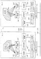
次に、本発明の好ましい実施の形態について、図面を参照して説明する。図1は本発明の実施の一形態のネットワークアドレス引継ぎ方法が適用されるネットワークの構成の一例を示している。 Next, a preferred embodiment of the present invention will be described with reference to the drawings. FIG. 1 shows an example of a network configuration to which a network address takeover method according to an embodiment of the present invention is applied.
典型的にはイーサネットで構築されたLAN(ローカルエリアネットワーク)201に対して、2台のサーバ1、2が接続している。これら2台のサーバ1、2は、一方が稼動系、他方が待機系として動作するものであり、正常動作時には、サーバ1が稼動系、サーバ2が待機系であるとする。サーバ1及びサーバ2は、LAN201内において、同一IP(Internet protocol)サブネット内のネットワークに接続しており、サーバ1のネットワークインターフェースは、IPアドレスとしてAを持ち、MAC(media access control)アドレスとしてaを持っている。またサーバ2のネットワークインターフェースは、IPアドレスとしてBを持ち、MACアドレスとしてbを持っている。ここではA≠Bであり、a≠bである。さらにサーバ1とサーバ2のネットワークインターフェースには、冗長構成用として、共通に、仮想IPアドレスCと仮想MACアドレスcとが設定されている。サーバ1とサーバ2との間には、LAN201を介して、コネクション202が確立しており、サーバ1、2は、コネクション202を介して論理的に接続している。
Typically, two
LAN201には、さらに、クライアント101〜104が接続しており、クライアント101〜104は、その必要とするサービスの提供を受けるために、サーバ1、2のうち現に稼動系となっているサーバに接続する。
Further,
ここに示したネットワークシステムでは、サーバ1とサーバ2の双方が仮想IPアドレスC及び仮想MACアドレスcを同時にアクティブに設定しても、待機系のサーバは、仮想IPアドレスC及び仮想MACアドレスcをあて先として用いる通信データを受け取った場合には、その通信データを、イーサネットフレーム上のデータ部分のみからなるデータとしてコネクション202を介して稼動系のサーバに転送する。その結果、仮想IPアドレスC及び仮想MACアドレスcに対しての通信は、すべて稼動系のサーバ1へと転送され、処理されることとなる。したがって、同一アドレスをあて先として指定する通信データが異なるサーバに分散して送られることによって生じる、通信データの矛盾や不一致が生じない。同一ネットワーク上に同一のIPアドレス及び同一のMACアドレスが設定されたサーバが存在しても、データの整合性が保証される。
In the network system shown here, even if both the
図2は、このようなサーバ1、2の具体的な構成を示している。サーバ1、2は、LAN201との接続点となる物理インターフェース301、401を備えている。物理インターフェース301、401には、その製造時に、それぞれ固有のMACアドレスa、bが設定されている。さらにサーバ1、2は、それぞれ、物理インターフェース301、401に付与されたMACアドレス(MACアドレスa、b)及びイーサネットの処理を行うイーサネット処理部302、402と、付与されているMACアドレスに関連付けられたIPアドレスの処理を行うIP処理部304、404と、IP処理部304、404で処理される実IPアドレスによるIPパケットに関する上位のプロトコル処理を行うTCP(transmission control protocl)/UDP(user datagram protocol)処理部305、405と、仮想MACアドレス及びイーサネットの処理を行う仮イーサネット処理部303、403と、仮想MACアドレスに関連付けられる仮想IPアドレスの処理を行う仮IP処理部306、406と、仮IP処理部306、406で処理される仮想IPアドレスによるIPパケットに関する上位のプロトコル処理を行う仮TCP/UDP処理部307、407と、それらのサーバが提供するサービスを実行するためのサービスプログラム309、409と、を備えている。さらにサーバ1、2は、コネクション202に関する処理を実行するために、それぞれ、コネクション処理部308、408を備えている。サーバ1のサービスプログラム309は、TCP/UDP処理部305及び仮TCP/UDP処理部307に任意にバインドすることができ、同様に、サーバ2のサービスプログラム409は、TCP/UDP処理部405及び仮TCP/UDP処理部407に任意にバインドすることができる。
FIG. 2 shows a specific configuration of
次に、本実施形態の動作を説明する。ここでは、当初はサーバ1が稼動系サーバであり、サーバ2が待機系サーバであるとする。
Next, the operation of this embodiment will be described. Here, initially, it is assumed that the
稼動系であるサーバ1に対して、その実MACアドレス(MACアドレスa)でアクセスがあった場合には、物理インターフェース301で受け付けられてイーサネット処理部302においてMACアドレス処理とイーサネット処理とがなされ、実MACアドレスに対応付けられた実IPアドレス(IPアドレスA)による処理がIP処理部304でなされ、さらに上位のプロトコル処理がTCP/UDP処理部305で行われることになる。また、稼動系であるサーバ1は、仮想MACアドレス及び仮想IPアドレスによるアクセスを受け付けた場合には、仮イーサネット処理部303において仮想MACアドレスの処理とイーサネット処理とがなされ、仮想MACアドレスに対応付けられた仮想IPアドレスによる処理が仮IP処理部306でなされ、さらに上位のプロトコル処理が仮TCP/UDP処理部307で行われることになる。同様に、待機系であるサーバ2に対して、その実アドレス(MACアドレスb)でアクセスがあった場合には、物理インターフェース401で受け付けられてイーサネット処理部402においてMACアドレス処理とイーサネット処理とがなされ、実MACアドレスに対応付けられた実IPアドレス(IPアドレスB)による処理がIP処理部404でなされ、さらに上位のプロトコル処理がTCP/UDP処理部405で行われることになる。
When the
待機系であるサーバ2に対して仮想MACアドレス及び仮想IPアドレスに基づいてアクセスがなされた場合には、仮イーサネット処理部403において仮想MACアドレスが処理されるともに、それらの通信データは、コネクション処理部408において、イーサネット部分のデータが処理され、イーサネットフレームにおけるデータ部分のみからなるデータとされる。そして、そのように処理されたデータは、コネクション202を介して、稼動系であるサーバ1のコネクション処理部308に転送される。そのようにデータが転送されると、稼動系であるサーバ1において、コネクション処理部308は、受信したデータ(イーサネットフレーム上のデータ)を仮イーサネット処理部303を経由してIP処理部306へ渡す。これにより、仮想IPアドレス及び仮想MACアドレスに対する通信データは、同一アドレスを持つ複数のホスト(ここでは稼動系のサーバ1及び待機系のサーバ2)に分散することなく、すべて稼動系のサーバ1の通信処理部に転送され、処理されることになる。したがって、同一の仮想IPアドレスや同一の仮想MACアドレスが異なる複数のサーバに割当てられていても、矛盾のない処理が可能となる。
When the
なお、このシステムでは、稼動系であるサーバ1において、そのサービスプログラム309が仮想アドレスを用いて通信データを送信する際には、サービスプログラム単位で送信するデータを、稼動系であるサーバ1の物理インターフェース301から送信してもよい。あるいは、コネクション処理部308、コネクション202、及び待機系であるサーバ2のコネクション処理部408を経由して、待機系のサーバ2の物理インターフェース401から送信してもよい。さらには、ランダムにあるいは規則的に稼動系のサーバ1の物理インターフェース301と待機系のサーバ2の物理インターフェース401のいずれかを選択してその物理インターフェースから送信するようにしてもよい。本実施形態のシステムでは、稼動系のサーバ1のサービスプログラム309がどの物理インターフェースをどのように用いて通信データを送信するかは、任意に設定可能である。
In this system, when the
次に、稼動系であるサーバ1に障害が発生した場合の処理について説明する。
Next, processing when a failure occurs in the
稼動系であるサーバ1で障害が発生し、そのサーバ1がサービス提供が不可能な状態になれば、サーバ1は、仮想IPアドレス及び仮想MACアドレスの使用を停止する。また、サーバ1に関連したネットワーク関連のハードウェアの障害の場合には、サーバ1の物理インターフェース301そのものが使用不可となる。このような場合、稼動系のサーバ1と待機系のサーバ2の間に生成されているコネクション202は、稼動系のサーバ1によって自発的に切断されるか、その障害自体によって切断される。
If a failure occurs in the
正常に動作している待機系のサーバ2は、コネクション202の切断をうけて稼動系のサーバ1での障害発生を検知する。サーバ1での障害発生を検知されると、そのことがコネクション処理部408から仮イーサネット処理部403に通知され、仮イーサネット処理部403は、仮想IPアドレス(IPアドレスC)及び仮想MACアドレス(MACアドレスc)を受け取った際の処理を切り替え、特に、データの送り先をコネクション処理部408から仮IP処理部406に切り替える。その結果、待機系のサーバ2では、それ以降、仮想IPアドレス(IPアドレスC)及び仮想MACアドレス(MACアドレスc)に対する通信データを受け取った場合、仮想MACアドレスに関する処理が仮イーサネット処理部403で行われるともに、その仮想MACアドレスに対応付けられた仮想IPアドレスの処理が仮IP処理部406で行われるようになる。そして仮想IPアドレスに対する上位のプロトコル処理が、仮TCP/UDP処理部407で行われ、そこにバインドされているサービスプログラム409に対してデータが受け渡される。結局、それまで待機系であったサーバ2が、稼動系のサーバとして動作することになる。
The
このとき、稼動系であったサーバ1においてはサービスプログラム309のみに障害が発生し、その他の処理部304〜308や物理インターフェース301には障害が発生せず、サービスプログラム309の再起動のみでその障害が復旧可能な場合には、再度、待機系であったサーバ2(現在稼動系として動作しているサーバ)との間にコネクション202を生成し、仮想IPアドレス及び仮想MACアドレスを稼動系であったサーバ1上で有効にする。その結果、稼動系であったサーバ1は復旧し、今度は、待機系のサーバとして動作を開始する。
At this time, in the
一方、稼動系であったサーバ1における障害が、回復するために保守者による復旧作業を必要とするものであった場合には、その後、保守者によってサーバ1の復旧作業が行われる。その結果、障害を起こしたサーバ1が復旧すれば、サーバ1は、待機系として動作を開始する。また、待機系であったサーバ2は稼動系として動作を行い続ける。さらに、管理者は、待機系と稼動系とのサーバの切り替えを手動操作によって行うことができる。現在、稼動系であるサーバに障害が生じた場合には、稼動系と待機系の切り替えが同様に行われる。
On the other hand, if the failure in the
以上、本発明の好ましい実施形態について、本発明に基づくネットワーク装置がサーバである場合について説明したが、本発明はこれに限定されるものではない。図3は、本発明に基づくネットワーク装置がルータである場合の、本発明のネットワークアドレス引継ぎ方法が適用されるネットワークの構成の一例を示している。 As mentioned above, although the case where the network apparatus based on this invention was a server was demonstrated about preferable embodiment of this invention, this invention is not limited to this. FIG. 3 shows an example of a network configuration to which the network address takeover method of the present invention is applied when the network device according to the present invention is a router.
イーサネットで構築されたLAN201に対して、2台のルータ3、4が接続している。これら2台のサーバ3、4は、一方が稼動系、他方が待機系として動作するものであり、ここでは説明のため、正常動作時には、サーバ3が稼動系、サーバ4が待機系であるとする。さらにこれのルータ3、4は、LAN201とは別のLAN203に対しても接続しており、LAN201とLAN203との間でのルーティングを実行する。LAN201側において、ルータ3、4は、同一IPサブネット内のネットワークに接続しており、ルータ3のネットワークインターフェースは、IPアドレスとしてAを持ち、MACアドレスとしてaを持っている。ルータ4のネットワークインターフェースは、IPアドレスBとMACアドレスbを持っている。ここではA≠Bであり、a≠bである。さらにルータ3及びルータ4のネットワークインターフェースには、冗長構成用として、共通に、仮想IPアドレスCと仮想MACアドレスcとが設定されている。ルータ3とルータ4との間には、LAN201を介して、コネクション202が確立しており、ルータ3、4は、コネクション202を介して論理的に接続している。LAN203側においても、ルータ3、4にはそれぞれ固有のIPアドレス及びMACアドレスが設定されるとともに、ルータ3、4に共通に、仮想IPアドレスと仮想MACアドレスが設定されている。LAN201には、さらに、クライアント101〜104が接続しており、クライアント101〜104は、ルータ3、4のうち現に稼動系となっているルータに接続する。
Two
ルータ3、4から構成されるこの稼動系−冗長系システムでは、稼動系と冗長系との間の切り替えとそれにともなうネットワークアドレス引継ぎの処理は、LAN201側から見た場合の処理もLAN203側から見た場合の処理も同様であるので、以下では、LAN201側から見た処理について説明する。
In this active system-redundant system composed of
上述したサーバ1、2の場合と同様に、ルータ3とルータ4が仮想IPアドレスC及び仮想MACアドレスcを同時にアクティブに設定しても、待機系のルータ4に対する仮想IPアドレスC及び仮想MACアドレスcをあて先として用いる通信データは、コネクション202を通じて、イーサネットフレーム上のデータ部分のみからなるデータとして、稼動系のルータ3へと転送される。その結果、仮想IPアドレスC及び仮想MACアドレスcに対しての通信は、すべて稼動系のルータ3へと転送され、処理されることとなる。したがって、同一のアドレスをあて先として指定する通信データが分散することによる、通信データの矛盾・不一致が生じない。同一ネットワーク上に同一のIPアドレス及びMACアドレスが設定されたノードが存在してもデータの整合性が保証される。
As in the case of the
このようなルータ3、4は、LAN203に対するネットワークインターフェースが設けられていることを除けば、図2に示したサーバ1、2と同じ構成を有している。ネットワークアドレス引継ぎの処理自体はLAN201側でもLAN203側でも同じであるので、以下では、LAN201側でのネットワークアドレス引継ぎの処理について、図2を参照して説明する。ただし、図2におけるサーバ1及びサーバ2は、それぞれ、ルータ3及びルータ4に読み替えるものとする。
ルータ3は、サーバ1と同様に、物理インターフェース301、イーサネット処理部302、仮イーサネット処理部303、IP処理部304、TCP/UDP処理部305、仮IP処理部306、仮TCP/UDP処理部307、コネクション処理部308及びサービスプログラム309を備えており、ルータ4は、サーバ2と同様に、物理インターフェース401、イーサネット処理部402、仮イーサネット処理部403、IP処理部404、TCP/UDP処理部405、仮IP処理部406、仮TCP/UDP処理部407、コネクション処理部408及びサービスプログラム409を備えている。サービスプログラム309、409としては、例えば、ルーティングエンジンやフィルタリングの機能を提供するものが挙げられる。ルータ3のサービスプログラム309は、TCP/UDP処理部305及び仮TCP/UDP処理部307に任意にバインドすることができ、ルータ4のサービスプログラム409は、TCP/UDP処理部405及び仮TCP/UDP処理部407に任意にバインドすることができる。
Similarly to the
次に、図3に示した稼動系のルータ3及び待機系のルータ4からなるシステムの動作について説明する。
Next, the operation of the system including the
稼動系のルータ3に対してその実MACアドレス(MACアドレスa)及び実IPアドレス(IPアドレスA)によってアクセスがなされた場合、あるいは待機系のルータ4に対してその実MACアドレス(MACアドレスb)及び実IPアドレス(IPアドレスB)によってアクセスがなされた場合には、上述と同様に、物理インターフェース301、401で受け付けられてイーサネット処理部302、402においてMACアドレス処理とイーサネット処理とがなされ、実IPアドレスによる処理がIP処理部304、404でなされ、さらに上位のプロトコル処理がTCP/UDP処理部305、405で行われる。また、稼動系であるルータ3は、仮想MACアドレス及び仮想IPアドレスによるアクセスを受け付けた場合には、仮イーサネット処理部303において仮想MACアドレスの処理とイーサネット処理とがなされ、仮想MACアドレスに対応付けられた仮想IPアドレスによる処理が仮IP処理部306でなされ、さらに上位のプロトコル処理が仮TCP/UDP処理部307で行われることになる。
When the
待機系であるルータ4に対して、仮想MACアドレス及び仮想IPアドレスをあて先とする通信データが送られて送ると、上述した場合と同様に、コネクション処理部408においてイーサネット部分のデータが処理され、イーサネットフレームにおけるデータ部分のみからなるデータのみとされ、この処理されたデータは、コネクション202を経由して稼動系のルータ3のコネクション処理部308へ転送される。稼動系のルータ3においては、コネクション処理部308は、コネクション202を介して受信したデータをイーサネット処理部303を経由してIP処理部306へ渡す。これにより、仮想IPアドレス及び仮想MACアドレスに対する通信データは、同一アドレスを持つ複数のホストに分散することなく、すべて稼動系のルータ3の通信処理部に転送され、処理されることになる。したがって、矛盾のない処理が可能となる。
When the communication data destined for the virtual MAC address and the virtual IP address is sent to the
稼動系のルータ3においてルーティングエンジンやフィルタリングなどのサービスプログラム309が仮想アドレスを用いて通信データを送信する際には、サービスプログラム単位で送信するデータを、稼動系のルータ3の物理インターフェース301から送信するか、コネクション202を介して待機系のルータ4の物理インターフェース401から送信するか、または、ランダムにあるいは予めで定められた規則にしたがっていずれかの物理インターフェース301、401を使用して送信するかを任意に設定可能である。
When the
稼動系のルータ3で障害が発生した場合の処理を説明する。ルータ3において障害が発生し、ルータ3がサービス提供が不可能な状態になれば、ルータ3は、仮想IPアドレス及び仮想MACアドレスの使用を停止する。またネットワーク関連のハードウェアの障害の場合には、ルータ3の物理インターフェース301そのものが使用不可となる。このような場合、稼動系のルータ3と待機系のルータ4の間で生成されているコネクション202が、稼動系のルータ3によって自発的に、あるいはその障害そのものに起因して、切断される。
Processing when a failure occurs in the
待機系のルータ4では、コネクション202の切断を受けて、稼動系のサーバ3での障害発生を検知し、それ以降は、仮想IPアドレス及び仮想MACアドレスをあて先とする通信データは、仮IP処理部406へ受け渡される。その後、ルータ4は、プロトコル処理を仮TCP/UDP処理部407において行い、そこにバインドされているサービスプログラム409へデータを受け渡す。
The
このとき、稼動系であったルータ3での障害はサービスプログラム309のみに発生し、そのルータ3の各処理部304〜308及び物理インターフェース301には障害は発生しておらず、そのサービスプログラムの再起動のみで障害が復旧可能な場合には、ルータ3と待機系であったルータ4との間に、再度、コネクション202を生成し、仮想IPアドレス及び仮想MACアドレスをルータ3上で有効にし、そのルータ3が待機系としての動作を開始するようにする。
At this time, the failure in the
一方、稼動系であったルータ3における障害が保守者による復旧作業を必要とするものであった場合には、保守者によって復旧が行われ、そのルータ3が復旧すれば、ルータ3は待機系のルータとしての動作を開始する。待機系であったルータ4は、稼動系のルータとしての動作を続行する。管理者によって待機系と稼動系とのルータの切り替えが行われるか、現在、稼動系であるルータに障害が生じた場合には、稼動系と待機系の切り替えが同様に行われる。
On the other hand, when the failure in the
以上、本発明の実施形態について、本発明に基づくネットワーク装置がサーバあるいはルータである場合について説明したが、本発明は、ネットワークインターフェースを有するあらゆるネットワーク装置に対して適用することができる。 As mentioned above, although the case where the network device based on this invention is a server or a router was demonstrated about embodiment of this invention, this invention is applicable with respect to all the network devices which have a network interface.
また、上述したサーバあるいはルータのような本発明に基づくネットワーク装置は、専用のハードウェア装置によって構成することもできるし、あるいは、このようなネットワーク装置を実現するためのコンピュータプログラムを汎用のコンピュータシステムに読み込ませ、そのプログラムを実行させることによっても実現できる。プログラムは、磁気テープやCD−ROMなどの記録媒体によってコンピュータに読み込まれ、あるいは、ネットワークを介してコンピュータに読み込まれる。 The network device according to the present invention such as the server or router described above can be configured by a dedicated hardware device, or a computer program for realizing such a network device can be used as a general-purpose computer system. It can also be realized by reading the program and executing the program. The program is read into the computer by a recording medium such as a magnetic tape or a CD-ROM, or is read into the computer via a network.
ネットワーク装置を構成するためのコンピュータは、具体的には、CPU(中央処理装置)と、プログラムやデータを格納するためのハードディスク装置と、主メモリと、キーボードやマウスあるいは入力用スイッチなどの入力装置と、CRTあるいは発光ダイオードを有する表示パネルなどの表示装置と、磁気テープやCD−ROM等の記録媒体を読み取る読み取り装置と、ネットワークとの接続部を構成する通信インターフェースと、から構成されている。通信インターフェースは、物理インターフェース301、401に対応するものである。ハードディスク装置、主メモリ、入力装置、表示装置、読み取り装置及び通信インターフェースは、いずれもCPUに接続している。このコンピュータシステムでは、上述したネットワーク装置を構成するためのプログラムを格納した記録媒体から読み出してハードディスク装置に格納し、あるいはネットワークを介してハードディスク装置に格納し、ハードディスク装置に格納されたプログラムをCPUが実行することにより、上述したネットワーク装置として機能する。
Specifically, a computer for configuring the network device includes a CPU (central processing unit), a hard disk device for storing programs and data, a main memory, and an input device such as a keyboard, a mouse, or an input switch. And a display device such as a display panel having a CRT or a light emitting diode, a reading device for reading a recording medium such as a magnetic tape or a CD-ROM, and a communication interface constituting a connection portion with a network. The communication interface corresponds to the
1、2 サーバ
3、4 ルータ
101〜104 クライアント
201、203 LAN(ローカルエリアネットワーク)
202 コネクション
301、401 物理インターフェース
302、402 イーサネット処理部
303、403 仮イーサネット処理部
304、404 IP処理部
305、405 TCP/UDP処理部
306、406 仮IP処理部
307、407 仮TCP/UDP処理部
308、408 コネクション処理部
309、409 サービスプログラム
1, 2
202
Claims (7)
前記第1及び第2のネットワーク装置の一方を稼動系、他方を待機系として冗長構成を構築する段階と、
前記第1及び第2のネットワーク装置の前記ネットワークインターフェースに対し、同一の仮想ネットワークアドレスを付与する段階と、
前記第1のネットワーク装置と前記第2のネットワーク装置との間で通信データ転送のためのコネクションを確立する段階と、
前記待機系であるネットワーク装置が、前記ネットワークから前記仮想ネットワークアドレスを用いて通信データが送信されてきた場合に、前記コネクションを介して前記通信データを前記稼動系であるネットワーク装置に転送する段階と、
前記コネクションが切断されたことによって、前記待機系であるネットワーク装置が前記稼動系であるネットワーク装置の障害を検知する段階と、
前記障害を検知した場合に、前記待機系であるネットワーク装置が、前記通信データの転送を取りやめて、自装置内で前記通信データに基づく処理を実行する段階と、
を有する、ネットワークアドレス引継ぎ方法。 A network address takeover method for taking over a network address between first and second network devices connected to the same network, each having a network interface and a unique network address assigned to each network interface,
Building a redundant configuration with one of the first and second network devices as an active system and the other as a standby system;
Assigning the same virtual network address to the network interfaces of the first and second network devices;
Establishing a connection for communication data transfer between the first network device and the second network device;
The network device as the standby system, when communication data is transmitted from the network using the virtual network address, transferring the communication data to the network device as the active system via the connection; ,
Detecting the failure of the network device as the active system by the network device as the standby system due to the disconnection of the connection;
When the failure is detected, the standby network device cancels transfer of the communication data, and executes processing based on the communication data in the own device;
A network address takeover method.
前記ネットワークに対して接続して固有のネットワークアドレスが設定されるとともに、前記ネットワーク内の他のネットワーク装置と共通の仮想ネットワークアドレスが設定される物理インターフェースと、
前記固有のネットワークアドレスを用いた通信データに対する処理を実行する第1の処理部と、
前記仮想ネットワークアドレスを用いた通信データに対する処理を実行する第2の処理部と、
前記他のネットワーク装置との間にコネクションを確立するコネクション処理部と、
を有し、
前記ネットワーク装置は前記他のネットワーク装置とともに稼動系及び待機系からなる冗長構成を形成し、
前記ネットワーク装置が待機系である場合に、前記第2の処理部は、前記仮想ネットワークアドレスを用いた通信データを前記コネクション処理部に渡し、前記コネクション処理部は渡された前記通信データを前記コネクションを介して前記他のネットワーク装置に転送し、前記コネクションの切断が検出されると、前記第2の処理部は前記仮想ネットワークアドレスを用いた通信データを前記コネクション処理部に渡すことなく自ら処理する、ネットワーク装置。 A network device connected to a network,
A physical interface connected to the network to set a unique network address and set a virtual network address common to other network devices in the network;
A first processing unit that executes processing on communication data using the unique network address;
A second processing unit that executes processing on communication data using the virtual network address;
A connection processing unit for establishing a connection with the other network device;
Have
The network device forms a redundant configuration consisting of an active system and a standby system together with the other network devices,
When the network device is a standby system, the second processing unit passes communication data using the virtual network address to the connection processing unit, and the connection processing unit passes the passed communication data to the connection. When the connection disconnection is detected, the second processing unit processes the communication data using the virtual network address without passing it to the connection processing unit. Network equipment.
前記ネットワーク内の他のコンピュータとの間にコネクションを確立する手順と、
前記コンピュータが稼動系及び待機系からなる冗長構成における待機系として動作している場合に、前記仮想ネットワークアドレスを用いて送信されてきた通信データを前記コネクションを介して前記稼動系であるネットワーク装置に転送する手順と、
前記コンピュータが前記待機系として動作している場合に、前記コネクションが切断されたことによって、前記稼動系である前記他のコンピュータの障害を検知する段階と、
前記コンピュータが前記待機系として動作している場合に、前記障害を検知したとき、前記通信データに基づく処理を実行する手順と、
を実行させるプログラム。 A computer that has a network interface with a unique network address and is connected to the network.
Establishing a connection with other computers in the network;
When the computer is operating as a standby system in a redundant configuration consisting of an active system and a standby system, communication data transmitted using the virtual network address is transmitted to the network apparatus that is the active system via the connection. Steps to transfer,
When the computer is operating as the standby system, detecting a failure of the other computer that is the active system by disconnecting the connection;
A procedure for executing processing based on the communication data when the failure is detected when the computer is operating as the standby system;
A program that executes
Priority Applications (1)
| Application Number | Priority Date | Filing Date | Title |
|---|---|---|---|
| JP2003370436A JP4133738B2 (en) | 2003-10-30 | 2003-10-30 | High-speed network address takeover method, network device, and program |
Applications Claiming Priority (1)
| Application Number | Priority Date | Filing Date | Title |
|---|---|---|---|
| JP2003370436A JP4133738B2 (en) | 2003-10-30 | 2003-10-30 | High-speed network address takeover method, network device, and program |
Publications (2)
| Publication Number | Publication Date |
|---|---|
| JP2005136690A JP2005136690A (en) | 2005-05-26 |
| JP4133738B2 true JP4133738B2 (en) | 2008-08-13 |
Family
ID=34647450
Family Applications (1)
| Application Number | Title | Priority Date | Filing Date |
|---|---|---|---|
| JP2003370436A Expired - Fee Related JP4133738B2 (en) | 2003-10-30 | 2003-10-30 | High-speed network address takeover method, network device, and program |
Country Status (1)
| Country | Link |
|---|---|
| JP (1) | JP4133738B2 (en) |
Families Citing this family (8)
| Publication number | Priority date | Publication date | Assignee | Title |
|---|---|---|---|---|
| JP2007208502A (en) * | 2006-01-31 | 2007-08-16 | Nec Infrontia Corp | Communication system, backup router, redundant processing program thereof, and redundant processing method thereof |
| JP4796184B2 (en) | 2007-03-28 | 2011-10-19 | 富士通株式会社 | Edge node redundancy system |
| JP5607011B2 (en) * | 2011-09-30 | 2014-10-15 | 富士通テレコムネットワークス株式会社 | Server redundancy system, virtual router and server |
| KR102251407B1 (en) * | 2014-09-03 | 2021-05-12 | 주식회사 케이티 | Duplex control system and method for control in software defined network |
| JP6485230B2 (en) * | 2015-06-03 | 2019-03-20 | 富士通株式会社 | COMMUNICATION DEVICE, COMMUNICATION SYSTEM, AND COMMUNICATION METHOD |
| US10652203B2 (en) | 2016-10-04 | 2020-05-12 | Mitsubishi Electric Corporation | Network system, communication control device and address setting method |
| EP3647888B1 (en) | 2018-10-31 | 2021-07-14 | Siemens Aktiengesellschaft | Control structure and method for operating the same |
| JP7495639B2 (en) * | 2020-08-28 | 2024-06-05 | 日本電信電話株式会社 | Update device, update method, and program |
-
2003
- 2003-10-30 JP JP2003370436A patent/JP4133738B2/en not_active Expired - Fee Related
Also Published As
| Publication number | Publication date |
|---|---|
| JP2005136690A (en) | 2005-05-26 |
Similar Documents
| Publication | Publication Date | Title |
|---|---|---|
| US10218782B2 (en) | Routing of communications to one or more processors performing one or more services according to a load balancing function | |
| US9379968B2 (en) | Redundancy support for network address translation (NAT) | |
| EP1653711B1 (en) | Fault tolerant network architecture | |
| EP3047631B1 (en) | Redundancy network protocol system | |
| US7894335B2 (en) | Redundant routing capabilities for a network node cluster | |
| US7609619B2 (en) | Active-active data center using RHI, BGP, and IGP anycast for disaster recovery and load distribution | |
| US7898941B2 (en) | Method and system for assigning a plurality of MACs to a plurality of processors | |
| CN101145972B (en) | A disaster tolerance network management system and login method of network management clients | |
| JP4133738B2 (en) | High-speed network address takeover method, network device, and program | |
| JPH09259096A (en) | Network high reliability method and system | |
| JP4378205B2 (en) | Blade type network relay device | |
| JP6490167B2 (en) | COMMUNICATION DEVICE, COMMUNICATION METHOD, COMPUTER PROGRAM, AND COMMUNICATION SYSTEM | |
| JP2007208502A (en) | Communication system, backup router, redundant processing program thereof, and redundant processing method thereof | |
| US11876709B2 (en) | Monitoring device, redundancy switching method, redundancy switching program, and network system | |
| JPH11313101A (en) | Method and system for speeding up connection reconnection in redundant LAN system | |
| JPH10224378A (en) | Control method of client server system and client server system | |
| JP2019161257A (en) | Packet transfer device, packet transfer system, packet transfer program, and packet transfer method | |
| KR20050092482A (en) | Method for converting protocol in a communication system | |
| HK1089024B (en) | Fault tolerant network architecture |
Legal Events
| Date | Code | Title | Description |
|---|---|---|---|
| RD04 | Notification of resignation of power of attorney |
Free format text: JAPANESE INTERMEDIATE CODE: A7424 Effective date: 20050621 |
|
| A621 | Written request for application examination |
Free format text: JAPANESE INTERMEDIATE CODE: A621 Effective date: 20060412 |
|
| A977 | Report on retrieval |
Free format text: JAPANESE INTERMEDIATE CODE: A971007 Effective date: 20080425 |
|
| TRDD | Decision of grant or rejection written | ||
| A01 | Written decision to grant a patent or to grant a registration (utility model) |
Free format text: JAPANESE INTERMEDIATE CODE: A01 Effective date: 20080514 |
|
| A01 | Written decision to grant a patent or to grant a registration (utility model) |
Free format text: JAPANESE INTERMEDIATE CODE: A01 |
|
| A61 | First payment of annual fees (during grant procedure) |
Free format text: JAPANESE INTERMEDIATE CODE: A61 Effective date: 20080602 |
|
| FPAY | Renewal fee payment (event date is renewal date of database) |
Free format text: PAYMENT UNTIL: 20110606 Year of fee payment: 3 |
|
| R150 | Certificate of patent or registration of utility model |
Free format text: JAPANESE INTERMEDIATE CODE: R150 |
|
| FPAY | Renewal fee payment (event date is renewal date of database) |
Free format text: PAYMENT UNTIL: 20120606 Year of fee payment: 4 |
|
| FPAY | Renewal fee payment (event date is renewal date of database) |
Free format text: PAYMENT UNTIL: 20130606 Year of fee payment: 5 |
|
| LAPS | Cancellation because of no payment of annual fees |