JP4134492B2 - In-cylinder internal combustion engine - Google Patents
In-cylinder internal combustion engine Download PDFInfo
- Publication number
- JP4134492B2 JP4134492B2 JP2000172415A JP2000172415A JP4134492B2 JP 4134492 B2 JP4134492 B2 JP 4134492B2 JP 2000172415 A JP2000172415 A JP 2000172415A JP 2000172415 A JP2000172415 A JP 2000172415A JP 4134492 B2 JP4134492 B2 JP 4134492B2
- Authority
- JP
- Japan
- Prior art keywords
- stroke
- compression stroke
- fuel
- intake
- combustion
- Prior art date
- Legal status (The legal status is an assumption and is not a legal conclusion. Google has not performed a legal analysis and makes no representation as to the accuracy of the status listed.)
- Expired - Fee Related
Links
Images


Classifications
-
- F—MECHANICAL ENGINEERING; LIGHTING; HEATING; WEAPONS; BLASTING
- F02—COMBUSTION ENGINES; HOT-GAS OR COMBUSTION-PRODUCT ENGINE PLANTS
- F02D—CONTROLLING COMBUSTION ENGINES
- F02D41/00—Electrical control of supply of combustible mixture or its constituents
- F02D41/30—Controlling fuel injection
- F02D41/3011—Controlling fuel injection according to or using specific or several modes of combustion
- F02D41/3064—Controlling fuel injection according to or using specific or several modes of combustion with special control during transition between modes
-
- F—MECHANICAL ENGINEERING; LIGHTING; HEATING; WEAPONS; BLASTING
- F02—COMBUSTION ENGINES; HOT-GAS OR COMBUSTION-PRODUCT ENGINE PLANTS
- F02B—INTERNAL-COMBUSTION PISTON ENGINES; COMBUSTION ENGINES IN GENERAL
- F02B3/00—Engines characterised by air compression and subsequent fuel addition
- F02B3/06—Engines characterised by air compression and subsequent fuel addition with compression ignition
- F02B3/10—Engines characterised by air compression and subsequent fuel addition with compression ignition with intermittent fuel introduction
- F02B3/12—Methods of operating
-
- F—MECHANICAL ENGINEERING; LIGHTING; HEATING; WEAPONS; BLASTING
- F02—COMBUSTION ENGINES; HOT-GAS OR COMBUSTION-PRODUCT ENGINE PLANTS
- F02B—INTERNAL-COMBUSTION PISTON ENGINES; COMBUSTION ENGINES IN GENERAL
- F02B69/00—Internal-combustion engines convertible into other combustion-engine type, not provided for in F02B11/00; Internal-combustion engines of different types characterised by constructions facilitating use of same main engine-parts in different types
- F02B69/06—Internal-combustion engines convertible into other combustion-engine type, not provided for in F02B11/00; Internal-combustion engines of different types characterised by constructions facilitating use of same main engine-parts in different types for different cycles, e.g. convertible from two-stroke to four stroke
-
- F—MECHANICAL ENGINEERING; LIGHTING; HEATING; WEAPONS; BLASTING
- F02—COMBUSTION ENGINES; HOT-GAS OR COMBUSTION-PRODUCT ENGINE PLANTS
- F02D—CONTROLLING COMBUSTION ENGINES
- F02D41/00—Electrical control of supply of combustible mixture or its constituents
- F02D41/30—Controlling fuel injection
- F02D41/3011—Controlling fuel injection according to or using specific or several modes of combustion
- F02D41/3017—Controlling fuel injection according to or using specific or several modes of combustion characterised by the mode(s) being used
- F02D41/3058—Controlling fuel injection according to or using specific or several modes of combustion characterised by the mode(s) being used the engine working with a variable number of cycles
-
- F—MECHANICAL ENGINEERING; LIGHTING; HEATING; WEAPONS; BLASTING
- F02—COMBUSTION ENGINES; HOT-GAS OR COMBUSTION-PRODUCT ENGINE PLANTS
- F02D—CONTROLLING COMBUSTION ENGINES
- F02D41/00—Electrical control of supply of combustible mixture or its constituents
- F02D41/30—Controlling fuel injection
- F02D41/38—Controlling fuel injection of the high pressure type
-
- F—MECHANICAL ENGINEERING; LIGHTING; HEATING; WEAPONS; BLASTING
- F02—COMBUSTION ENGINES; HOT-GAS OR COMBUSTION-PRODUCT ENGINE PLANTS
- F02D—CONTROLLING COMBUSTION ENGINES
- F02D41/00—Electrical control of supply of combustible mixture or its constituents
- F02D41/30—Controlling fuel injection
- F02D41/38—Controlling fuel injection of the high pressure type
- F02D41/40—Controlling fuel injection of the high pressure type with means for controlling injection timing or duration
- F02D41/402—Multiple injections
-
- F—MECHANICAL ENGINEERING; LIGHTING; HEATING; WEAPONS; BLASTING
- F02—COMBUSTION ENGINES; HOT-GAS OR COMBUSTION-PRODUCT ENGINE PLANTS
- F02B—INTERNAL-COMBUSTION PISTON ENGINES; COMBUSTION ENGINES IN GENERAL
- F02B1/00—Engines characterised by fuel-air mixture compression
- F02B1/02—Engines characterised by fuel-air mixture compression with positive ignition
- F02B1/04—Engines characterised by fuel-air mixture compression with positive ignition with fuel-air mixture admission into cylinder
-
- F—MECHANICAL ENGINEERING; LIGHTING; HEATING; WEAPONS; BLASTING
- F02—COMBUSTION ENGINES; HOT-GAS OR COMBUSTION-PRODUCT ENGINE PLANTS
- F02B—INTERNAL-COMBUSTION PISTON ENGINES; COMBUSTION ENGINES IN GENERAL
- F02B1/00—Engines characterised by fuel-air mixture compression
- F02B1/12—Engines characterised by fuel-air mixture compression with compression ignition
-
- F—MECHANICAL ENGINEERING; LIGHTING; HEATING; WEAPONS; BLASTING
- F02—COMBUSTION ENGINES; HOT-GAS OR COMBUSTION-PRODUCT ENGINE PLANTS
- F02B—INTERNAL-COMBUSTION PISTON ENGINES; COMBUSTION ENGINES IN GENERAL
- F02B75/00—Other engines
- F02B75/02—Engines characterised by their cycles, e.g. six-stroke
- F02B2075/022—Engines characterised by their cycles, e.g. six-stroke having less than six strokes per cycle
- F02B2075/027—Engines characterised by their cycles, e.g. six-stroke having less than six strokes per cycle four
-
- F—MECHANICAL ENGINEERING; LIGHTING; HEATING; WEAPONS; BLASTING
- F02—COMBUSTION ENGINES; HOT-GAS OR COMBUSTION-PRODUCT ENGINE PLANTS
- F02B—INTERNAL-COMBUSTION PISTON ENGINES; COMBUSTION ENGINES IN GENERAL
- F02B75/00—Other engines
- F02B75/12—Other methods of operation
- F02B2075/125—Direct injection in the combustion chamber for spark ignition engines, i.e. not in pre-combustion chamber
-
- F—MECHANICAL ENGINEERING; LIGHTING; HEATING; WEAPONS; BLASTING
- F02—COMBUSTION ENGINES; HOT-GAS OR COMBUSTION-PRODUCT ENGINE PLANTS
- F02D—CONTROLLING COMBUSTION ENGINES
- F02D41/00—Electrical control of supply of combustible mixture or its constituents
- F02D41/30—Controlling fuel injection
- F02D41/38—Controlling fuel injection of the high pressure type
- F02D2041/389—Controlling fuel injection of the high pressure type for injecting directly into the cylinder
-
- Y—GENERAL TAGGING OF NEW TECHNOLOGICAL DEVELOPMENTS; GENERAL TAGGING OF CROSS-SECTIONAL TECHNOLOGIES SPANNING OVER SEVERAL SECTIONS OF THE IPC; TECHNICAL SUBJECTS COVERED BY FORMER USPC CROSS-REFERENCE ART COLLECTIONS [XRACs] AND DIGESTS
- Y02—TECHNOLOGIES OR APPLICATIONS FOR MITIGATION OR ADAPTATION AGAINST CLIMATE CHANGE
- Y02T—CLIMATE CHANGE MITIGATION TECHNOLOGIES RELATED TO TRANSPORTATION
- Y02T10/00—Road transport of goods or passengers
- Y02T10/10—Internal combustion engine [ICE] based vehicles
- Y02T10/12—Improving ICE efficiencies
-
- Y—GENERAL TAGGING OF NEW TECHNOLOGICAL DEVELOPMENTS; GENERAL TAGGING OF CROSS-SECTIONAL TECHNOLOGIES SPANNING OVER SEVERAL SECTIONS OF THE IPC; TECHNICAL SUBJECTS COVERED BY FORMER USPC CROSS-REFERENCE ART COLLECTIONS [XRACs] AND DIGESTS
- Y02—TECHNOLOGIES OR APPLICATIONS FOR MITIGATION OR ADAPTATION AGAINST CLIMATE CHANGE
- Y02T—CLIMATE CHANGE MITIGATION TECHNOLOGIES RELATED TO TRANSPORTATION
- Y02T10/00—Road transport of goods or passengers
- Y02T10/10—Internal combustion engine [ICE] based vehicles
- Y02T10/40—Engine management systems
Landscapes
- Engineering & Computer Science (AREA)
- Chemical & Material Sciences (AREA)
- Combustion & Propulsion (AREA)
- Mechanical Engineering (AREA)
- General Engineering & Computer Science (AREA)
- Electrical Control Of Air Or Fuel Supplied To Internal-Combustion Engine (AREA)
- Combustion Methods Of Internal-Combustion Engines (AREA)
- Exhaust-Gas Circulating Devices (AREA)
- Output Control And Ontrol Of Special Type Engine (AREA)
Description
【0001】
【発明の属する技術分野】
本発明は、第1圧縮行程,第1膨張行程,第2圧縮行程及び第2膨張行程が順次繰り返される、筒内噴射型内燃機関に関する。
【0002】
【従来の技術】
近年、内燃機関において燃焼サイクルを改良し、高効率及び排ガスの浄化を図った技術が提案されている。
例えば特開平9−4459号公報には、それぞれスパークプラグがそなえられた主燃焼室と副燃焼室とを有するエンジンが開示されている。このエンジンによれば、主燃焼室(主室)及び副燃焼室(副室)において、室内の混合気をそれぞれスパークプラグで着火して独立して燃焼を行なわせることにより、一回の圧縮行程で2回の膨張行程を行なって理論熱効率の向上を図ろうとしている。
【0003】
【発明が解決しようとする課題】
しかしながら上述した従来の技術では、通常の燃焼室(主燃焼室)の他に副燃焼室が設けられるとともに、主燃焼室と副燃焼室とにそれぞれスパークプラグがそなえられており、構造が複雑となって製造コストが大幅に高くなってしまうという課題がある。また、一回の圧縮行程で2回の膨張行程を行なうべく主室混合気と副室混合気とを別々のタイミングで燃焼させているに過ぎず、排ガスの性状については、通常の内燃機関と大差のないことが予想される。
【0004】
本発明は、このような課題に鑑み創案されたもので、製造コストを大幅に増加させることなく低燃費と排ガス浄化とを高次元で両立できるようにした、筒内噴射型内燃機関を提供することを目的とする。
【0005】
【課題を解決するための手段】
このため、請求項1記載の本発明の筒内噴射型内燃機関では、頂面に半球状に窪んだキャビティが形成されたピストンと、上記キャビティと協働して燃焼室内で吸気による逆タンブル流を形成させる吸気ポートとを有し、第1圧縮行程,第1膨張行程,第2圧縮行程及び第2膨張行程が順次繰り返されるとともに、第2膨張行程の後半と第1圧縮行程の前半との間の所定期間において排気及び吸気が行なわれ、第1燃焼過程として、第1圧縮行程中に噴射された燃料が、第1圧縮行程から第1膨張行程にかけて燃焼し、第2燃焼過程として第1膨張行程中に、第1燃焼過程において発生した既燃ガス中に噴射された追加燃料が第2圧縮行程から第2膨張行程にかけて燃焼する。
【0006】
この時、排気及び吸気が、第2膨張行程の後半と第1圧縮行程の前半との間の所定期間において、オーバラップして行なわれるようになるので、ポンピングロスが抑制される。また、第2膨張行程の後半と第1圧縮行程の前半との間の所定期間でしか、排気及び吸気が行なわれないので、第2燃焼過程で発生した既燃ガスは、完全には排出されず、その後に行なわれる第1燃焼過程は、残留ガス(既燃ガス)を比較的多く含んだ雰囲気下で行なわれ、一方、第2燃焼過程では、第1燃焼過程で発生した高温の既燃ガスに噴射された追加燃料が、高温の雰囲気下で気化/分解を経て活性化して燃焼する。
【0007】
上記請求項1において、第1燃焼過程は希薄成層燃焼であることが好ましい。これにより、ポンピングロスを一層抑制することができ、また、第1燃焼過程において、酸素が多く含まれるようになるので、既燃ガス中に酸素と未燃物とが共存し易くなって、第2燃焼過程の燃焼効率を向上させることができる。
また、追加燃料は、第1膨張行程で噴射され、第2圧縮行程で既燃ガスと十分に混合される。
【0008】
また、第2燃焼過程が圧縮自着火により多点着火される。
【0009】
請求項2記載の本発明の筒内噴射型内燃機関では、排気が吸気よりも早期に開始されるので、吸気弁が開弁されると排気に引かれて吸気が速やかに行なわれ、また、吸気が排気よりも遅れて終了するので、排気弁が開弁されている最中は、排気が吸気(新気)により効率よく押し出される。
請求項3記載の本発明の筒内噴射型内燃機関では、過給装置により過給が行なわれ、掃気が効率よく安定して行なわれる。
【0010】
請求項4記載の本発明の筒内噴射型内燃機関では、第1圧縮行程,第1膨張行程,第2圧縮行程及び第2膨張行程が順次繰り返される運転モードと、吸気行程,圧縮行程,膨張行程及び排気行程が順次繰り返される通常の4サイクル運転モードとが可変動弁機構により切り換えられ、高負荷運転時には通常の4サイクル運転モードで運転される。
【0011】
【発明の実施の形態】
以下、図面を参照して本発明の実施の形態について説明する。
まず、本発明の一実施形態としての筒内噴射型内燃機関について説明する。図1〜図6は本実施形態の筒内噴射型内燃機関について示す図である。
まず、本実施形態としての筒内噴射型内燃機関(以下、単にエンジンともいう)の構成について説明する。
【0012】
図1に示すように、エンジン1のシリンダヘッド2には、各シリンダ3毎に点火プラグ4と燃焼室5内に直接開口する燃料噴射弁6とが設けられ、点火プラグ4は点火コイル4Aにより燃料噴射弁6はドライバ6Aによりそれぞれ駆動される。シリンダ3内には、クランクシャフト7に連結されたピストン8が装備され、このピストン8の頂面には半球状に窪んだキャビティ9が形成されている。
【0013】
シリンダヘッド2には、吸気弁10を介して燃焼室5と連通しうる吸気ポート11と排気弁12を介して燃焼室5と連通しうる排気ポート13とが形成されている。吸気ポート11は燃焼室5上方に略鉛直に配設され、ピストン8の頂面のキャビティ9と協働して燃焼室5内で吸気による逆タンブル流を形成させる。
また、シリンダ3外周のウォータジャケット15には冷却水温を検出する水温センサ16が設けられ、クランクシャフト7には所定のクランク角位置で信号を出力するクランク角センサ17が、吸気弁10,排気弁12を駆動するカムシャフト18,19にはカムシャフト位置に応じた気筒識別信号を出力する気筒識別センサ(カム角センサ)20が、それぞれ付設されている。
【0014】
また、カムシャフト18,19と吸気弁10,排気弁12との間には、可変動弁機構41が装備されており、一般的な4ストロ−ク1サイクル運転(通常の4サイクル運転)、つまり、1サイクル中に、吸気行程,圧縮行程,膨張行程,排気行程の4行程を行なう通常運転に対応した作動モードと、後述の変則的な4サイクル運転(以下、変則4サイクル運転という)に対応した作動モードとを選択的に切り換えることができるようになっている。この可変動弁機構41には、公知の種々のものを適用できるので説明は省略する。
【0015】
吸気系は、上流側からエアクリーナ21,吸気管22,スロットルボディ23,サージタンク24,吸気マニホールド25の順に構成され、吸気マニホールド25の下流端部に吸気ポート11が設けられている。スロットルボディ23には、アクセル開度に応じて燃焼室5内へ流入する空気量を調整する電子制御式スロットル弁(ETV)30がそなえられ、このETV30の開度制御は、アクセル開度に応じた制御のみならず、アイドルスピード制御や、後述するリーン運転時の大量吸気導入の制御も行なえるようになっている。さらに、エアクリーナ21の直ぐ下流部分には吸入空気流量を検出するエアフローセンサ37が、スロットルボディ23にはETV30のスロットル開度を検出するスロットルポジションセンサ38とETV30の全閉を検出してアイドル信号を出力するアイドルスイッチ39とがそれぞれ設けられている。
【0016】
排気系は、上流側から排気ポート13を有する排気マニホールド26,排気管27の順に構成され、排気管27には排ガス浄化用の三元触媒29が介装され、排気マニホールド26には、O2センサ40が設けられている。
なお、燃料供給系については図示しないが、圧力が所定の高圧力〔数十気圧(例えば2〜7MPa)程度〕に調整された燃料が燃料噴射弁6に導かれ、燃料噴射弁6から高圧燃料が噴射されるようになっている。
【0017】
そして、点火プラグ4,燃料噴射弁6といった各エンジン制御要素の作動を制御するために、内燃機関の制御手段としての機能を有する電子制御ユニット(ECU)60がそなえられている。このECU60には、入出力装置,制御プログラムや制御マップ等の記憶を行なう記憶装置,中央処理装置,タイマやカウンタ等がそなえられており、前述の種々のセンサ類からの検出情報やキースイッチの位置情報等に基づいて、このECU60が、上述の各エンジン制御要素の制御を行なうようになっている。
【0018】
特に、本エンジンは、筒内噴射エンジンであり、燃料噴射を自由なタイミングで実施でき、吸気行程を中心とした燃料噴射によって均一混合させ均一燃焼を行なうほか、圧縮行程を中心とした燃料噴射によって前述の逆タンブル流を利用して層状燃焼を行なうことができる。
また、本エンジンの場合、1燃焼サイクルを吸気行程,圧縮行程,膨張行程,排気行程の4行程によって行なう一般的な4サイクル運転の他、1燃焼サイクルにおいて圧縮行程,膨張行程をそれぞれ2回ずつ行なう変則4サイクル運転も可能になっており、この変則4サイクル運転モードは、層状燃焼を主体とした第1燃焼過程と均一燃焼主体とした第2燃焼過程との2つの燃焼過程を1サイクル内にそなえている。
【0019】
ECU60では、図示しないマップに基づいて、エンジン回転速度(以下、エンジン回転数という)Ne及びエンジン負荷状態を示す平均有効圧Peの目標値(目標Pe)に応じていずれかの運転モードを選択するようになっており、エンジン回転数Neが所定値Ne0よりも小さく、目標Peが所定値Pe0よりも小さい領域では変則4サイクル運転モードを選択し、エンジン回転数Neが所定値Ne0以上又は目標Peが所定値Pe0以上の領域では一般的な4サイクル運転モードを選択する。このとき、一般的な4サイクルと変則4サイクルとの切り換えは可変動弁機構41を用いて行なう。
【0020】
上述のように、このエンジンの場合、変則4サイクル運転のモードは、高負荷運転時及び高回転運転時を除いた部分負荷時に行なうようになっている。
ここで、本エンジンのサイクルについて説明すると、本エンジンでは、図2に示すように、第1圧縮行程▲2▼,第1膨張行程▲3▼,第2圧縮行程▲4▼,第2膨張行程▲5▼が順次繰り返される変則的な4ストローク1サイクル運転(変則4サイクル運転)が実行され、第2膨張行程▲5▼の後半と第1圧縮行程▲2▼の前半との間〔第2膨張行程▲5▼と第1圧縮行程▲2▼との間且つ燃焼室内のピストンが下死点(BDC)近傍にある期間〕で、吸気▲1▼と排気▲6▼とがオーバラップして行なわれるようになっている。ここでは、排気弁12の開弁期間中心CEは、第2膨張行程▲5▼の末期に設定され、吸気弁10の開弁期間中心CIは、第1圧縮行程▲2▼の初期に設定されており、排気▲6▼を吸気▲1▼よりも早期に開始させるとともに吸気▲1▼を排気▲6▼よりも遅れて終了させることで掃気が効率よく行なわれるようになっている。
【0021】
また、上述の如く燃焼室5内では吸気による逆タンブル流が形成されるため、この逆タンブル流によっても高い掃気効率が得られる。
そして、本エンジンでは、第1圧縮行程▲2▼中に噴射された燃料を第1圧縮行程▲2▼から第1膨張行程▲3▼にかけて燃焼させる第1燃焼過程と、この第1燃焼過程で発生した既燃ガス中に追加燃料を噴射して、この追加燃料を第2圧縮行程▲4▼から第2膨張行程▲5▼にかけて燃焼させる第2燃焼過程とをそなえている。これらの各行程は、図4(図4は両対数グラフ)のPV線図に示すようになる。
【0022】
なお、図2に示すように、第2燃焼過程においては、第1膨張行程▲3▼,第2圧縮行程▲4▼の内のいずれかの時点で燃料噴射を行なうことが可能であるが、本実施形態では、第1膨張行程▲3▼中に追加燃料噴射(2回目の噴射)を行なう例を示している。
また、本変則4サイクル運転では、オープン制御により空燃比を目標空燃とするようになっており、ECU60では、エンジン運転状態に応じて主燃料噴射の目標空燃比及びトータルの目標空燃比を独立して設定し、主燃料噴射(1回目の噴射)の燃料噴射量、及び主燃料噴射と追加燃料噴射(2回目の噴射)との燃料噴射量の総和量が、吸気行程で吸入された空気量に対してそれぞれ所定の目標空燃比となるように、主燃料噴射量、及び燃料噴射量の総和をそれぞれ制御するようになっている。本実施形態では、主燃料噴射で略1/2弱の量の燃料を噴射し、追加燃料噴射で残りの略1/2強の量の燃料を噴射するようにしている。
【0023】
なお、上述の目標空燃比は目標Pe及びエンジン回転数Neに応じてマップに基づいて設定されるが、掃気時における吸気の吹き抜けが存在するためエアフローセンサ37から検出される吸気量に対してはリーンな値が設定されている。
また、本実施形態では、図2に示すように、第1燃焼過程においては、第1圧縮行程▲2▼の上死点(TDC)直前に点火プラグ4による点火を行ない、第2燃焼過程においては、第2圧縮行程▲4▼の上死点(TDC)直前に点火プラグ4による点火を行なうようになっている。ただし、第2燃焼過程においては、筒内温度が十分に高ければ圧縮行程で自着火するので、圧縮自着火によって確実に燃焼できる場合には、図3に示すように、点火プラグ4による点火を行なわないようようにする。この圧縮自着火が可能になるか否かはエンジンの回転速度やエンジン負荷や1回目と2回目との燃料噴射量の割合,1回目の燃焼の空燃比,2回目の燃料噴射時期等に依存する。なお、ガソリンエンジンの場合、第1燃焼過程においては、一般に筒内温度は自着火するほど高くならないので、点火プラグ4により確実に点火を行なうのが望ましい。
【0024】
本発明の一実施形態としての筒内噴射型内燃機関は、上述のように構成されているので、目標Peが所定値Pe0未満でエンジン回転数Neが所定値Ne0未満の部分負荷時には、図2に示すように、第1圧縮行程▲2▼,第1膨張行程▲3▼,第2圧縮行程▲4▼,第2膨張行程▲5▼の順に変則4サイクル運転を行なう。
つまり、まず、ピストン8の下降時に、排気弁12及び吸気弁10をこの順に開弁して、吸気▲1▼と排気▲6▼とをオーバラップさせて掃気を行なう。
【0025】
ついで、ピストン8の上昇時に、排気弁12及び吸気弁10をこの順に閉弁して、図5(a)に示すように、ピストン8が上昇する過程で燃料噴射弁6から燃料を噴射(主燃料噴射)する(第1圧縮行程▲2▼)。この場合、この主燃料噴射は、吸気行程▲1▼で吸入された空気量に対して、目標となる空燃比に相当する燃料量の略1/2の量の燃料が噴射される。
【0026】
さらに、ピストン8が圧縮上死点の近傍に到達したら点火プラグ4によって火花点火を行なう。これによって、図5(b)に示すように、1回目の燃焼が行なわれる。この1回目の燃焼は、図5(c)に示すように、全体の空燃比をリーンとしながら点火プラグ4の近傍に着火可能な燃料濃度の高い混合気を集めて行なう、希薄層状燃焼(希薄成層燃焼)となって、第1膨張行程▲3▼が行なわれる。
【0027】
図5(d)に示すように、この1回目の燃焼(第1燃焼過程)後の第1膨張行程▲3▼の途中、又は図示しないが第2圧縮行程▲4▼の途中で、高温の既燃ガス中に追加燃料を噴射すると、筒内には、燃料と既燃ガス中の多くの活性種(燃焼可能な成分)と余剰酸素とが高温雰囲気下で共存する。
その後の第2圧縮行程▲4▼では、上記の高温ガスが圧縮されるため、図5(e)に示すように、高温,高圧下で燃料の分解も促進されて且つ空気と燃料との混合も促進されて、第2圧縮行程▲4▼の上死点近傍で点火プラグ4により火花点火すれば極めて効率良く、2回目の燃焼(第2燃焼過程)が行なわれる。
【0028】
また、筒内温度が十分に高ければ、図5(f)に示すように、点火プラグ4により火花点火しなくとも圧縮行程の末期(第2圧縮行程▲4▼の上死点近傍)に筒内の燃料は温度と圧力とによって自ら着火する。この場合、燃料の追加噴射終了から第2圧縮行程▲4▼の上死点までのインターバルが十分にあれば燃料と既燃ガスとの混合が進んで均質な混合気となって、筒内(燃焼室)内の各部で着火する多点自着火となって、極めて効率良く、2回目の燃焼(第2燃焼過程)が行なわれる。このように行なわれる本エンジンの変則4サイクル運転によれば、吸気▲1▼直後の圧縮行程噴射(主燃料噴射)による希薄成層火花点火燃焼(第1燃焼過程での燃焼)は、ポンピングロスが小さく、効率の高い燃焼となる。
【0029】
第1燃焼過程での燃焼直後に行なわれる第2燃焼過程での燃焼では、反応途中の活性の高い大量の未燃物と酸素とを含んだ高温の既燃ガス中にさらに燃料が噴射され、この噴射された燃料自身も高温雰囲気で急速に気化,分解して活性化するので、極めて燃焼しやすくなる。この燃焼(第2燃焼過程での燃焼)によれば、HCやNOXを含んだ上記の未燃物も同時に再反応するので、極めて高効率な運転となって排ガス中の浄化すべき成分(エミッション)は極めて低レベルなものになる。また、NOXの一部は、再圧縮時(第2圧縮行程)▲4▼に燃料から離脱したHと効果的に反応してこの圧縮中に還元される。
【0030】
この第2燃焼過程での燃焼を火花点火で行なう場合には、燃焼を確実に行なうことができ、さらに、残留ガス中のNOXが残留ガス中のCO2によって希釈されてNOXの排出レベルを低レベルにすることができる。
一方、第2燃焼過程での燃焼を圧縮自着火で行なう場合には、上述のように予混合気の多点着火となるので、NOXやHCやSOOT(煤)の排出量は共に極めて低いレベルにすることができ、燃焼効率は高められる。
【0031】
さらに、第1燃焼過程及び第2燃焼過程の結果の排ガスは、上記のような燃焼後の排気行程▲6▼で排出されるので、エンジン外に排出される実際のエミッションは極めて低レベルなものになる。
また、第2膨張行程▲5▼の後半と第1圧縮行程▲2▼の前半との間の僅かな所定期間で排気▲6▼及び吸気▲1▼が行なわれるので、第2燃焼過程▲5▼において発生した既燃ガスが筒内から完全には排除されず、第1燃焼過程は残留ガスを比較的多く含んだ状態で行なわれ、この点からもNOXの発生が抑制される。
【0032】
しかも、従来のエンジンに対し、運転サイクルを変更するだけで構造的な変更は殆どないので、上記効果を、製造コストを大きく増加させることなく得られる。
また、1回目の噴射燃料量と2回目の噴射燃料量との割合や、2回目の燃料噴射時期の設定を調整することで、第2燃焼行程における作動ガスとなる既燃ガス中の酸素濃度やCO2,CO等の燃焼生成物濃度、さらにはガス温度を適宜に変更することができるので、制御の自由度が極めて高く、さらには、広い負荷,速度範囲で予混合圧縮着火(圧縮自着火)を実現することも可能である。
【0033】
さらに、吸気系に外部EGRを導入することを廃止することも可能になり、吸気系の汚損や吸気系内へのカーボン堆積を回避することができる。
また、リーンNOX触媒を廃止することも可能になるので、コストを削減でき、また、エンジンの制御も簡素化できる。
なお、図6はNOX排出量,HC排出量,正味燃費率を示す図であり、a線は一般的な4サイクル予混合燃焼に関し、b線は一般的な4サイクル希薄成層燃焼に関し、c線は変則4サイクル運転に関している。また、1はNOX排出量に関し、2はHC排出量に関し、3は正味燃費率に関している。本エンジンでは、負荷が所定値Pe0未満では変則4サイクル運転が行なわれ、負荷が所定値Pe0以上では、一般的な4サイクル予混合燃焼による運転が行なわれるので、図6より、広い軸トルク範囲(エンジン負荷範囲)で、NOX排出量,HC排出量,正味燃費率を良好なものに保持できることがわかる。
【0034】
ところで、本発明の筒内噴射型内燃機関は、上記の実施形態に限定されるものではなく、本発明の趣旨を逸脱しない範囲で種々変形して実施することができる。例えば上記の実施形態では、追加燃料の噴射タイミングを第1膨張行程▲3▼中に行なっているが、この追加燃料の噴射タイミングを、第1膨張行程▲3▼から第2圧縮行程▲4▼にかけて又は第2圧縮行程▲4▼内で行なっても、十分に追加燃料の活性化や空気との混合が図れる場合も考えられ、かかる設定も可能である。
【0035】
また、上記の実施形態では、主燃料噴射(1回目の噴射)を総和量の1/2弱としているが、第1燃焼過程で行なう希薄成層燃焼は、当量比が大き過ぎると大量の不活性ガスによって燃焼が困難になり、また、当量比が小さすぎると安定した着火ができないので、略0.1〜0.5程度の範囲に設定することが望ましく、このような範囲内であれば適宜設定し得る。
【0036】
ただし、1回目の噴射燃料量と2回目の噴射燃料量との割合は、1回目の燃焼と2回目の燃焼との差に起因する振動や、2回目の燃焼の高温自着火を実現するための残留ガス量や温度に影響を与える。1回目の噴射燃料量をリッチにし過ぎると、残留ガス濃度が過大(当量比0.5でEGR率100%に相当)となるので、この点からも1回目の噴射燃料量を制限することが必要であり、これらを考慮すると、1回目の噴射燃料量を制限し、この分2回目の噴射燃料量を増大して対応することが望ましい。
【0037】
また、本実施形態では、低負荷域のみに変則4サイクルを適用しているが、これは負荷が大きいと吸気量不足を招くことを考慮したもので、例えば過給装置を装備させ、この過給装置により過給を行なって高負荷域でも十分な吸気量が得られるようにして、高負荷域でも変則4サイクル運転を実行するように構成しても良い。この場合、図6に鎖線で示すように、軸トルクが大きい(エンジン高負荷)場合にも正味燃費率が向上する。
【0038】
また、変則4サイクル運転のみ行なう(通常4サイクル運転は行なわない)構成も考えられる。
【0039】
【発明の効果】
以上詳述したように、請求項1記載の本発明の筒内噴射型内燃機関によれば、排気及び吸気が、第2膨張行程の後半と第1圧縮行程の前半との間の所定期間において、オーバラップして行なわれるようになるので、ポンピングロスが抑制され、さらに、4ストローク中に2回燃焼が行なわれるので、吸気行程,圧縮行程,膨張行程及び排気行程を順次実行する一般的な4ストローク1サイクル運転に比べて、特に低負荷領域では、効率が高く燃費も良好になる。
【0040】
また、第2燃焼過程では、第1燃焼過程により発生した高温の既燃ガス中に追加燃料を噴射するので、この追加燃料は高温雰囲気で急速に気化,分解して活性し、極めて燃焼し易くなって、未燃ガスの再反応が促進されて高効率な燃焼を実現することができ、NOXやHCの排出を十分に抑制し得るようになる。また、第2膨張行程の後半と第1圧縮行程の前半との間の所定期間でしか、排気及び吸気が行なわれないので、第2燃焼過程において発生した既燃ガスが筒内から完全には排除されず、第1燃焼過程は残留ガスを比較的多く含んだ状態で行なわれることとなって、この点からもNOXの発生が抑制される。
【0041】
したがって、運転サイクルを変更するだけで構造的には従来に対し殆ど変更がないので、製造コストを大幅に増加させることなく低燃費と排ガス浄化とを高次元で両立できるようになるという利点がある。
請求項2記載の本発明の筒内噴射型内燃機関によれば、追加燃料が、第2圧縮行程で既燃ガスと十分に混合されるので、既燃ガス中のNOXと効率良く反応してNOXを還元でき、したがって、排ガス浄化を一層効果的に行なうことができるという利点がある。
【0042】
請求項3記載の本発明の筒内噴射型内燃機関によれば、火花点火により、第2燃焼過程を適切なタイミングで確実に行なうことができ、また、既燃ガス中のCO2に希釈されてNOXの排出レベルを効率よく抑制できるという利点がある。
請求項4記載の本発明の筒内噴射型内燃機関によれば、圧縮自着火させることにより、第2燃焼過程を多点着火とすることができ、NOX,SOOT及びHCの排出レベルを効率よく抑制できるという利点がある。
【0043】
請求項5記載の本発明の筒内噴射型内燃機関によれば、排気が吸気よりも早期に開始されるので、吸気弁が開弁されると排気に引かれて吸気が速やかに行なわれ、また、吸気が排気よりも遅れて終了するので、排気弁が開弁されている最中は、排気が吸気(新気)により押し出され、したがって、掃気及び新気導入を効率よく行なうことができるという利点がある。
【0044】
請求項6記載の本発明の筒内噴射型内燃機関によれば、過給装置により過給が行なわれるので、高負荷域でも吸気が効率よく安定して行なわれ、運転可能な負荷領域を拡大できるという利点がある。
請求項7記載の本発明の筒内噴射型内燃機関によれば、可変動弁機構により運転モードの切り換えが行なわれ、高負荷運転時には、吸気行程,圧縮行程,膨張行程及び排気行程が順次繰り返される通常の4サイクル運転モードに切り換えられるので、安定して出力が得られるという利点がある。
【図面の簡単な説明】
【図1】本発明の一実施形態としての筒内噴射型内燃機関を示す構成図である。
【図2】本発明の一実施形態としての筒内噴射型内燃機関の動作を示すタイムチャートである。
【図3】本発明の一実施形態としての筒内噴射型内燃機関の動作を示すタイムチャートである。
【図4】本発明の一実施形態としての筒内噴射型内燃機関の動作を示すPV線図である。
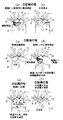
【図5】本発明の一実施形態としての筒内噴射型内燃機関の動作を(a)〜(f)の順で示す模式的断面図である。
【図6】本発明の一実施形態としての筒内噴射型内燃機関の効果を示す図である。
【符号の説明】
1 筒内噴射型内燃機関(エンジン)
4 点火プラグ
10 吸気弁
12 排気弁
41 可変動弁機構
60 ECU[0001]
BACKGROUND OF THE INVENTION
The present invention relates to a direct injection internal combustion engine in which a first compression stroke, a first expansion stroke, a second compression stroke, and a second expansion stroke are sequentially repeated.
[0002]
[Prior art]
In recent years, a technique has been proposed in which a combustion cycle is improved in an internal combustion engine to achieve high efficiency and purification of exhaust gas.
For example, Japanese Patent Laid-Open No. 9-4459 discloses an engine having a main combustion chamber and a sub-combustion chamber each provided with a spark plug. According to this engine, in the main combustion chamber (main chamber) and the sub-combustion chamber (sub-chamber), the air-fuel mixture in the chamber is ignited by the spark plugs and independently burned, so that one compression stroke is performed. In order to improve the theoretical thermal efficiency, two expansion strokes are performed.
[0003]
[Problems to be solved by the invention]
However, in the conventional technology described above, a sub-combustion chamber is provided in addition to a normal combustion chamber (main combustion chamber), and a spark plug is provided in each of the main combustion chamber and the sub-combustion chamber, resulting in a complicated structure. Thus, there is a problem that the manufacturing cost is significantly increased. Further, the main chamber mixture and the sub-chamber mixture are merely burned at different timings so as to perform two expansion strokes in one compression stroke. It is expected that there will be no big difference.
[0004]
The present invention has been devised in view of such problems, and provides a direct injection internal combustion engine that can achieve both high fuel efficiency and exhaust gas purification at a high level without significantly increasing manufacturing costs. For the purpose.
[0005]
[Means for Solving the Problems]
Therefore, in the in-cylinder internal combustion engine of the first aspect of the present invention, a piston having a hemispherical cavity formed on the top surface and a reverse tumble flow by intake air in the combustion chamber in cooperation with the cavity. The first compression stroke, the first expansion stroke, the second compression stroke, and the second expansion stroke are sequentially repeated, and the second half of the second expansion stroke and the first half of the first compression stroke Exhaust and intake are performed during a predetermined period, and as the first combustion process, the fuel injected during the first compression stroke burns from the first compression stroke to the first expansion stroke, and as the second combustion processDuring the first expansion strokeThe additional fuel injected into the burned gas generated in the first combustion process burns from the second compression stroke to the second expansion stroke.
[0006]
At this time, exhaust and intake air are overlapped in a predetermined period between the second half of the second expansion stroke and the first half of the first compression stroke, so that pumping loss is suppressed. Further, since exhaust and intake are performed only during a predetermined period between the second half of the second expansion stroke and the first half of the first compression stroke, the burned gas generated in the second combustion process is completely discharged. The first combustion process performed thereafter is performed in an atmosphere containing a relatively large amount of residual gas (burned gas), while the second combustion process has a high temperature burned gas generated in the first combustion process. The additional fuel injected into the gas is activated and burned through vaporization / decomposition in a high temperature atmosphere.
[0007]
In the first aspect, the first combustion process is preferably lean stratified combustion. As a result, the pumping loss can be further suppressed, and more oxygen is contained in the first combustion process, so that oxygen and unburned substances easily coexist in the burned gas. The combustion efficiency of the two combustion processes can be improved.
Also, Additional fuelIsInjected in the first expansion stroke and sufficiently mixed with the burned gas in the second compression stroke.
[0008]
AlsoThe second combustion process is ignited in multiple points by compression auto-ignition.
[0009]
Claim2In the in-cylinder injection internal combustion engine of the present invention described above, the exhaust gas is started earlier than the intake air. Therefore, when the intake valve is opened, the intake air is drawn quickly and the intake air is exhausted. Therefore, the exhaust is efficiently pushed out by the intake air (fresh air) while the exhaust valve is being opened.
Claim3In the in-cylinder injection internal combustion engine of the present invention described above, supercharging is performed by the supercharging device, and scavenging is performed efficiently and stably.
[0010]
Claim4In the in-cylinder internal combustion engine of the present invention, the first compression stroke, the first expansion stroke, the second compression stroke, and the second expansion stroke are sequentially repeated, the intake stroke, the compression stroke, the expansion stroke, and the exhaust. The normal four-cycle operation mode in which the stroke is sequentially repeated is switched by the variable valve mechanism, and the operation is performed in the normal four-cycle operation mode at the time of high load operation.
[0011]
DETAILED DESCRIPTION OF THE INVENTION
Embodiments of the present invention will be described below with reference to the drawings.
First, a direct injection internal combustion engine as an embodiment of the present invention will be described. 1-6 is a figure shown about the cylinder injection type internal combustion engine of this embodiment.
First, the configuration of a direct injection internal combustion engine (hereinafter also simply referred to as an engine) as the present embodiment will be described.
[0012]
As shown in FIG. 1, the
[0013]
An
A
[0014]
Further, a
[0015]
The intake system is configured from the upstream side in the order of an
[0016]
The exhaust system includes an
Although the fuel supply system is not shown, the fuel whose pressure is adjusted to a predetermined high pressure (several tens of atmospheres (for example, about 2 to 7 MPa)) is guided to the
[0017]
In order to control the operation of each engine control element such as the
[0018]
In particular, this engine is an in-cylinder injection engine. Fuel injection can be performed at any timing, and uniform mixing is performed by fuel injection centered on the intake stroke to perform uniform combustion, and fuel injection centered on the compression stroke. Stratified combustion can be performed using the above-described reverse tumble flow.
In addition, in the case of this engine, in addition to a general four-cycle operation in which one combustion cycle is performed by four strokes of an intake stroke, a compression stroke, an expansion stroke, and an exhaust stroke, the compression stroke and the expansion stroke are performed twice each in one combustion cycle. Anomalous four-cycle operation is also possible, and this irregular four-cycle operation mode includes two combustion processes, a first combustion process mainly composed of stratified combustion and a second combustion process mainly composed of uniform combustion within one cycle. Is prepared.
[0019]
The
[0020]
As described above, in the case of this engine, the irregular four-cycle operation mode is performed at the time of partial load except during high load operation and during high rotation operation.
Here, the cycle of the engine will be described. In the engine, as shown in FIG. 2, the first compression stroke (2), the first expansion stroke (3), the second compression stroke (4), and the second expansion stroke. An irregular four-stroke one-cycle operation (an irregular four-cycle operation) in which (5) is sequentially repeated is executed, and between the second half of the second expansion stroke (5) and the first half of the first compression stroke (2) [second During the expansion stroke (5) and the first compression stroke (2) and during which the piston in the combustion chamber is in the vicinity of the bottom dead center (BDC), the intake (1) and the exhaust (6) overlap. It is supposed to be done. Here, the valve opening period center C of the
[0021]
Further, as described above, since a reverse tumble flow is formed by intake air in the
In this engine, the first combustion process in which the fuel injected during the first compression stroke (2) is burned from the first compression stroke (2) to the first expansion stroke (3), and in the first combustion process There is provided a second combustion process in which additional fuel is injected into the generated burned gas and this additional fuel is combusted from the second compression stroke (4) to the second expansion stroke (5). Each of these steps is as shown in the PV diagram of FIG. 4 (FIG. 4 is a log-log graph).
[0022]
As shown in FIG. 2, in the second combustion process, it is possible to perform fuel injection at any point in the first expansion stroke (3) and the second compression stroke (4). In the present embodiment, an example in which additional fuel injection (second injection) is performed during the first expansion stroke (3) is shown.
In the irregular four-cycle operation, the air-fuel ratio is set to the target air fuel by open control, and the
[0023]
The target air-fuel ratio described above is set based on the map in accordance with the target Pe and the engine speed Ne. However, since there is intake air blow-in during scavenging, the intake air amount detected from the
Further, in the present embodiment, as shown in FIG. 2, in the first combustion process, ignition is performed by the
[0024]
Since the direct injection internal combustion engine as one embodiment of the present invention is configured as described above, the target Pe is a predetermined value Pe.0If the engine speed Ne is less than the predetermined value Ne0When the partial load is less than 1, as shown in FIG. 2, the irregular four-cycle operation is performed in the order of the first compression stroke (2), the first expansion stroke (3), the second compression stroke (4), and the second expansion stroke (5). To do.
That is, first, when the
[0025]
Next, when the
[0026]
Further, when the
[0027]
As shown in FIG. 5 (d), during the first expansion stroke (3) after the first combustion (first combustion process) or during the second compression stroke (4) (not shown) When additional fuel is injected into the burned gas, the fuel, many active species (combustible components) in the burned gas, and surplus oxygen coexist in a high-temperature atmosphere.
In the subsequent second compression step (4), the high-temperature gas is compressed, so that the decomposition of the fuel is promoted at a high temperature and a high pressure as shown in FIG. If the spark is ignited by the
[0028]
Also, if the in-cylinder temperature is sufficiently high, as shown in FIG. 5 (f), the cylinder will be in the final stage of the compression stroke (near the top dead center of the second compression stroke (4)) without spark ignition by the
[0029]
In the combustion in the second combustion process performed immediately after the combustion in the first combustion process, fuel is further injected into the high-temperature burned gas containing a large amount of unburned matter and oxygen having high activity during the reaction, Since the injected fuel itself is rapidly vaporized, decomposed and activated in a high temperature atmosphere, it becomes extremely easy to burn. According to this combustion (combustion in the second combustion process), HC and NOXSince the above-mentioned unburned matter containing selenium also reacts at the same time, the operation (emission) to be purified in the exhaust gas becomes extremely low because the operation becomes extremely efficient. NOXA part of the gas effectively reacts with H released from the fuel during the recompression (second compression stroke) (4) and is reduced during the compression.
[0030]
In the case where the combustion in the second combustion process is performed by spark ignition, combustion can be performed reliably, and NO in the residual gas can be further increased.XCO in residual gas2Diluted by NOXThe emission level can be lowered.
On the other hand, when the combustion in the second combustion process is performed by compression auto-ignition, the premixed gas is ignited at multiple points as described above.XAnd HC and SOOT (soot) emissions can both be reduced to an extremely low level, and combustion efficiency can be improved.
[0031]
Further, since the exhaust gas resulting from the first combustion process and the second combustion process is exhausted in the exhaust stroke (6) after combustion as described above, the actual emission discharged outside the engine is at a very low level. become.
Further, since the exhaust (6) and the intake (1) are performed in a slight predetermined period between the second half of the second expansion stroke (5) and the first half of the first compression stroke (2), the second combustion process (5) The burnt gas generated in ▼ is not completely removed from the cylinder, and the first combustion process is performed with a relatively large amount of residual gas.XIs suppressed.
[0032]
In addition, since the structural change is hardly made only by changing the operation cycle with respect to the conventional engine, the above effect can be obtained without greatly increasing the manufacturing cost.
Also, by adjusting the ratio of the first and second injected fuel amounts and the setting of the second fuel injection timing, the oxygen concentration in the burned gas that becomes the working gas in the second combustion stroke And CO2, CO and other combustion product concentrations, as well as the gas temperature, can be changed as appropriate, so the degree of freedom of control is extremely high, and premixed compression ignition (compression autoignition) is possible over a wide load and speed range. It can also be realized.
[0033]
Furthermore, it is possible to eliminate the introduction of the external EGR into the intake system, and it is possible to avoid contamination of the intake system and carbon accumulation in the intake system.
Also, lean NOXSince the catalyst can be abolished, the cost can be reduced and the control of the engine can be simplified.
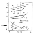
FIG. 6 shows NO.XIt is a figure which shows an emission amount, HC emission amount, and a net fuel consumption rate, a line relates to general four-cycle premixed combustion, b line relates to general four-cycle lean stratified combustion, and c line relates to irregular four-cycle operation. Yes. 1 is NOXRegarding emissions, 2 relates to HC emissions, and 3 relates to net fuel efficiency. In this engine, the load is a predetermined value Pe.0If it is less than that, irregular four-cycle operation is performed, and the load is a predetermined value Pe.0In the above, since the operation by the general four-cycle premixed combustion is performed, the NOx in a wider shaft torque range (engine load range) than FIG.XIt can be seen that the emissions, HC emissions, and net fuel efficiency can be kept good.
[0034]
By the way, the direct injection internal combustion engine of the present invention is not limited to the above-described embodiment, and various modifications can be made without departing from the spirit of the present invention. For example, in the above embodiment, the injection timing of the additional fuel is performed during the first expansion stroke (3). The injection timing of the additional fuel is changed from the first expansion stroke (3) to the second compression stroke (4). Even if it is carried out until the second compression stroke (4), the additional fuel can be sufficiently activated and mixed with air, and such setting is also possible.
[0035]
In the above embodiment, the main fuel injection (the first injection) is set to a little less than half of the total amount. However, the lean stratified combustion performed in the first combustion process is inactive in a large amount when the equivalence ratio is too large. Combustion by gas becomes difficult, and if the equivalent ratio is too small, stable ignition cannot be performed. Therefore, it is desirable to set a range of about 0.1 to 0.5. Can be set.
[0036]
However, the ratio between the first injected fuel amount and the second injected fuel amount is to realize the vibration caused by the difference between the first combustion and the second combustion and the high temperature auto-ignition of the second combustion. Affects the amount of residual gas and temperature. If the amount of fuel injected for the first time is made too rich, the residual gas concentration becomes excessive (equivalent ratio of 0.5 and corresponds to an EGR rate of 100%). From this point as well, the amount of fuel injected for the first time may be limited. In view of these, it is desirable to limit the amount of fuel injected for the first time and increase the amount of fuel injected for the second time accordingly.
[0037]
In the present embodiment, the irregular four cycles are applied only to the low load range. However, this takes into consideration that the intake amount is insufficient when the load is large. For example, a supercharger is provided and this overload is provided. An irregular four-cycle operation may be performed even in the high load range by supercharging by the supply device so that a sufficient intake amount can be obtained even in the high load range. In this case, as indicated by a chain line in FIG. 6, the net fuel efficiency is improved even when the shaft torque is large (engine high load).
[0038]
In addition, a configuration in which only irregular four-cycle operation is performed (normally four-cycle operation is not performed) is also conceivable.
[0039]
【The invention's effect】
As described above in detail, according to the direct injection internal combustion engine of the first aspect of the present invention, the exhaust gas and the intake air are discharged in a predetermined period between the second half of the second expansion stroke and the first half of the first compression stroke. Since the pumping loss is suppressed and the combustion is performed twice during four strokes, the intake stroke, the compression stroke, the expansion stroke, and the exhaust stroke are sequentially executed. Compared with the 4-stroke 1-cycle operation, the efficiency is high and the fuel consumption is also improved particularly in the low load region.
[0040]
Further, in the second combustion process, additional fuel is injected into the high-temperature burned gas generated in the first combustion process, so that this additional fuel is rapidly vaporized and decomposed in a high-temperature atmosphere and activated, making it extremely easy to burn. Therefore, re-reaction of unburned gas is promoted, and highly efficient combustion can be realized.XAnd HC emissions can be sufficiently suppressed. Further, since exhaust and intake are performed only in a predetermined period between the second half of the second expansion stroke and the first half of the first compression stroke, the burned gas generated in the second combustion process is completely discharged from the cylinder. In this respect, the first combustion process is performed in a state containing a relatively large amount of residual gas.XIs suppressed.
[0041]
Therefore, there is an advantage that both fuel efficiency and exhaust gas purification can be achieved at a high level without significantly increasing the manufacturing cost since there is almost no change in structure just by changing the operation cycle. .
According to the in-cylinder injection internal combustion engine of the present invention, the additional fuel is sufficiently mixed with the burned gas in the second compression stroke.XReacts efficiently with NOXTherefore, there is an advantage that exhaust gas purification can be performed more effectively.
[0042]
According to the in-cylinder injection internal combustion engine of the third aspect of the present invention, the second combustion process can be reliably performed at an appropriate timing by spark ignition, and the CO in the burned gas can be performed.2Diluted to NOXThere is an advantage that the emission level can be efficiently suppressed.
According to the in-cylinder injection internal combustion engine of the present invention, the second combustion process can be made to be multipoint ignition by performing compression self-ignition.X, SOOT and HC emission levels can be efficiently suppressed.
[0043]
According to the in-cylinder injection internal combustion engine of the fifth aspect of the present invention, the exhaust gas is started earlier than the intake air. Therefore, when the intake valve is opened, the exhaust gas is drawn and exhausted quickly. Further, since the intake air is terminated later than the exhaust gas, the exhaust gas is pushed out by the intake air (fresh air) while the exhaust valve is opened, and therefore scavenging and fresh air introduction can be performed efficiently. There is an advantage.
[0044]
According to the in-cylinder injection internal combustion engine of the present invention described in
According to the in-cylinder injection internal combustion engine of the present invention, the operation mode is switched by the variable valve mechanism, and the intake stroke, the compression stroke, the expansion stroke, and the exhaust stroke are sequentially repeated during high load operation. Therefore, there is an advantage that the output can be stably obtained.
[Brief description of the drawings]
FIG. 1 is a configuration diagram showing a direct injection internal combustion engine as an embodiment of the present invention.
FIG. 2 is a time chart showing the operation of the direct injection internal combustion engine as one embodiment of the present invention.
FIG. 3 is a time chart showing the operation of the direct injection internal combustion engine as one embodiment of the present invention.
FIG. 4 is a PV diagram showing the operation of the direct injection internal combustion engine as one embodiment of the present invention.
FIG. 5 is a schematic cross-sectional view showing the operation of the direct injection internal combustion engine as one embodiment of the present invention in the order of (a) to (f).
FIG. 6 is a diagram showing the effect of a direct injection internal combustion engine as one embodiment of the present invention.
[Explanation of symbols]
1 In-cylinder injection internal combustion engine (engine)
4 Spark plug
10 Intake valve
12 Exhaust valve
41 Variable valve mechanism
60 ECU
Claims (4)
第1圧縮行程,第1膨張行程,第2圧縮行程及び第2膨張行程が順次繰り返されるとともに、
該第2膨張行程の後半と該第1圧縮行程の前半との間の所定期間において排気及び吸気が行なわれ、
該第1圧縮行程中に噴射された燃料を、該第1圧縮行程から該第1膨張行程にかけて燃焼させる第1燃焼過程と、
該第1膨張行程中に、該第1燃焼過程において発生した既燃ガス中に追加燃料を噴射し、該追加燃料を該第2圧縮行程から該第2膨張行程にかけて圧縮自着火燃焼させる第2燃焼過程とをそなえて構成されている
ことを特徴とする、筒内噴射型内燃機関。A piston in which a cavity recessed in a hemispherical shape is formed on the top surface, and an intake port that cooperates with the cavity to form a reverse tumble flow by intake air in the combustion chamber;
The first compression stroke, the first expansion stroke, the second compression stroke, and the second expansion stroke are sequentially repeated,
Exhaust and intake are performed in a predetermined period between the second half of the second expansion stroke and the first half of the first compression stroke,
A first combustion process in which fuel injected during the first compression stroke is combusted from the first compression stroke to the first expansion stroke;
During the first expansion stroke, a second fuel is injected into the burned gas generated in the first combustion process, and the second fuel is compressed by self-ignition combustion from the second compression stroke to the second expansion stroke. An in-cylinder internal combustion engine characterized by comprising a combustion process.
ことを特徴とする、請求項1記載の筒内噴射型内燃機関。The in-cylinder injection internal combustion engine according to claim 1, wherein the exhaust gas is started earlier than the intake air, and the intake air is ended later than the exhaust gas.
ことを特徴とする、請求項1記載の筒内噴射型内燃機関。2. The direct injection internal combustion engine according to claim 1, further comprising a supercharging device.
高負荷運転時には、該可変動弁機構により該通常の4サイクル運転モードに切り換えられる
ことを特徴とする、請求項1記載の筒内噴射型内燃機関。The operation mode in which the first compression stroke, the first expansion stroke, the second compression stroke, and the second expansion stroke are sequentially repeated, and the normal four-cycle operation mode in which the intake stroke, the compression stroke, the expansion stroke, and the exhaust stroke are sequentially repeated. And a variable valve mechanism that switches between
The in-cylinder injection internal combustion engine according to claim 1, wherein the high-load operation is switched to the normal four-cycle operation mode by the variable valve mechanism.
Priority Applications (3)
| Application Number | Priority Date | Filing Date | Title |
|---|---|---|---|
| JP2000172415A JP4134492B2 (en) | 2000-06-08 | 2000-06-08 | In-cylinder internal combustion engine |
| US09/875,900 US6622690B2 (en) | 2000-06-08 | 2001-06-08 | Direct injection type internal combustion engine and controlling method therefor |
| DE10127951A DE10127951B4 (en) | 2000-06-08 | 2001-06-08 | Direct injection internal combustion engine and control method therefor |
Applications Claiming Priority (1)
| Application Number | Priority Date | Filing Date | Title |
|---|---|---|---|
| JP2000172415A JP4134492B2 (en) | 2000-06-08 | 2000-06-08 | In-cylinder internal combustion engine |
Publications (2)
| Publication Number | Publication Date |
|---|---|
| JP2001349232A JP2001349232A (en) | 2001-12-21 |
| JP4134492B2 true JP4134492B2 (en) | 2008-08-20 |
Family
ID=18674820
Family Applications (1)
| Application Number | Title | Priority Date | Filing Date |
|---|---|---|---|
| JP2000172415A Expired - Fee Related JP4134492B2 (en) | 2000-06-08 | 2000-06-08 | In-cylinder internal combustion engine |
Country Status (3)
| Country | Link |
|---|---|
| US (1) | US6622690B2 (en) |
| JP (1) | JP4134492B2 (en) |
| DE (1) | DE10127951B4 (en) |
Families Citing this family (61)
| Publication number | Priority date | Publication date | Assignee | Title |
|---|---|---|---|---|
| JP2002004913A (en) * | 2000-06-26 | 2002-01-09 | Nissan Motor Co Ltd | Compression self-ignition internal combustion engine |
| SE523733C2 (en) * | 2001-11-30 | 2004-05-11 | Scania Cv Ab | Procedure for fuel injection in an internal combustion engine and internal combustion engine |
| AT5937U1 (en) * | 2001-12-27 | 2003-01-27 | Avl List Gmbh | METHOD FOR OPERATING AN INTERNAL COMBUSTION ENGINE |
| US6712037B2 (en) * | 2002-01-09 | 2004-03-30 | Visteon Global Technologies, Inc. | Low pressure direct injection engine system |
| JP4069711B2 (en) * | 2002-03-28 | 2008-04-02 | マツダ株式会社 | Diesel engine combustion control system |
| JP2004036429A (en) * | 2002-07-01 | 2004-02-05 | Toyota Motor Corp | Control device for internal combustion engine |
| JP2004092614A (en) * | 2002-09-04 | 2004-03-25 | Honda Motor Co Ltd | Air flow sensor failure judgment device |
| DE10244364A1 (en) * | 2002-09-24 | 2004-04-01 | Daimlerchrysler Ag | Internal combustion engine with auto-ignition |
| US6851408B2 (en) * | 2002-12-25 | 2005-02-08 | Nissan Motor Co., Ltd. | Direct fuel injection engine |
| US6901897B2 (en) * | 2003-09-05 | 2005-06-07 | General Motors Corporation | Method and intake cam for retaining exhaust residuals for emissions reduction in a diesel engine |
| JP4407581B2 (en) * | 2004-11-30 | 2010-02-03 | 株式会社デンソー | Gas fuel engine |
| US7395786B2 (en) * | 2005-11-30 | 2008-07-08 | Ford Global Technologies, Llc | Warm up strategy for ethanol direct injection plus gasoline port fuel injection |
| US7302933B2 (en) | 2005-11-30 | 2007-12-04 | Ford Global Technologies Llc | System and method for engine with fuel vapor purging |
| US7730872B2 (en) | 2005-11-30 | 2010-06-08 | Ford Global Technologies, Llc | Engine with water and/or ethanol direct injection plus gas port fuel injectors |
| US7877189B2 (en) | 2005-11-30 | 2011-01-25 | Ford Global Technologies, Llc | Fuel mass control for ethanol direct injection plus gasoline port fuel injection |
| US7293552B2 (en) | 2005-11-30 | 2007-11-13 | Ford Global Technologies Llc | Purge system for ethanol direct injection plus gas port fuel injection |
| US8132555B2 (en) * | 2005-11-30 | 2012-03-13 | Ford Global Technologies, Llc | Event based engine control system and method |
| US7357101B2 (en) | 2005-11-30 | 2008-04-15 | Ford Global Technologies, Llc | Engine system for multi-fluid operation |
| US7640912B2 (en) * | 2005-11-30 | 2010-01-05 | Ford Global Technologies, Llc | System and method for engine air-fuel ratio control |
| US8434431B2 (en) | 2005-11-30 | 2013-05-07 | Ford Global Technologies, Llc | Control for alcohol/water/gasoline injection |
| US7412966B2 (en) | 2005-11-30 | 2008-08-19 | Ford Global Technologies, Llc | Engine output control system and method |
| US7594498B2 (en) * | 2005-11-30 | 2009-09-29 | Ford Global Technologies, Llc | System and method for compensation of fuel injector limits |
| US7406947B2 (en) | 2005-11-30 | 2008-08-05 | Ford Global Technologies, Llc | System and method for tip-in knock compensation |
| US7278396B2 (en) * | 2005-11-30 | 2007-10-09 | Ford Global Technologies, Llc | Method for controlling injection timing of an internal combustion engine |
| US7647916B2 (en) * | 2005-11-30 | 2010-01-19 | Ford Global Technologies, Llc | Engine with two port fuel injectors |
| US7581528B2 (en) | 2006-03-17 | 2009-09-01 | Ford Global Technologies, Llc | Control strategy for engine employng multiple injection types |
| US7779813B2 (en) * | 2006-03-17 | 2010-08-24 | Ford Global Technologies, Llc | Combustion control system for an engine utilizing a first fuel and a second fuel |
| US7665428B2 (en) | 2006-03-17 | 2010-02-23 | Ford Global Technologies, Llc | Apparatus with mixed fuel separator and method of separating a mixed fuel |
| US7578281B2 (en) | 2006-03-17 | 2009-08-25 | Ford Global Technologies, Llc | First and second spark plugs for improved combustion control |
| US8267074B2 (en) | 2006-03-17 | 2012-09-18 | Ford Global Technologies, Llc | Control for knock suppression fluid separator in a motor vehicle |
| US7933713B2 (en) | 2006-03-17 | 2011-04-26 | Ford Global Technologies, Llc | Control of peak engine output in an engine with a knock suppression fluid |
| US7533651B2 (en) | 2006-03-17 | 2009-05-19 | Ford Global Technologies, Llc | System and method for reducing knock and preignition in an internal combustion engine |
| US7647899B2 (en) * | 2006-03-17 | 2010-01-19 | Ford Global Technologies, Llc | Apparatus with mixed fuel separator and method of separating a mixed fuel |
| US7389751B2 (en) * | 2006-03-17 | 2008-06-24 | Ford Global Technology, Llc | Control for knock suppression fluid separator in a motor vehicle |
| US7740009B2 (en) | 2006-03-17 | 2010-06-22 | Ford Global Technologies, Llc | Spark control for improved engine operation |
| US8015951B2 (en) | 2006-03-17 | 2011-09-13 | Ford Global Technologies, Llc | Apparatus with mixed fuel separator and method of separating a mixed fuel |
| US7665452B2 (en) * | 2006-03-17 | 2010-02-23 | Ford Global Technologies, Llc | First and second spark plugs for improved combustion control |
| US7275516B1 (en) * | 2006-03-20 | 2007-10-02 | Ford Global Technologies, Llc | System and method for boosted direct injection engine |
| US7681554B2 (en) | 2006-07-24 | 2010-03-23 | Ford Global Technologies, Llc | Approach for reducing injector fouling and thermal degradation for a multi-injector engine system |
| US20080022657A1 (en) * | 2006-07-28 | 2008-01-31 | Caterpillar Inc. | Power source thermal management and emissions reduction system |
| US7909019B2 (en) | 2006-08-11 | 2011-03-22 | Ford Global Technologies, Llc | Direct injection alcohol engine with boost and spark control |
| US7287509B1 (en) | 2006-08-11 | 2007-10-30 | Ford Global Technologies Llc | Direct injection alcohol engine with variable injection timing |
| JP2006348947A (en) * | 2006-08-18 | 2006-12-28 | Kazuo Oyama | Internal combustion engine with exhaust pressure regenerator |
| US7426916B2 (en) * | 2006-10-30 | 2008-09-23 | Ford Global Technologies, Llc | Multi-stroke internal combustion engine for facilitation of auto-ignition operation |
| US7461628B2 (en) | 2006-12-01 | 2008-12-09 | Ford Global Technologies, Llc | Multiple combustion mode engine using direct alcohol injection |
| US7676321B2 (en) | 2007-08-10 | 2010-03-09 | Ford Global Technologies, Llc | Hybrid vehicle propulsion system utilizing knock suppression |
| US8214130B2 (en) | 2007-08-10 | 2012-07-03 | Ford Global Technologies, Llc | Hybrid vehicle propulsion system utilizing knock suppression |
| US7971567B2 (en) * | 2007-10-12 | 2011-07-05 | Ford Global Technologies, Llc | Directly injected internal combustion engine system |
| JP4793382B2 (en) * | 2007-12-07 | 2011-10-12 | トヨタ自動車株式会社 | Fuel injection control device for internal combustion engine |
| US8118009B2 (en) | 2007-12-12 | 2012-02-21 | Ford Global Technologies, Llc | On-board fuel vapor separation for multi-fuel vehicle |
| US8550058B2 (en) | 2007-12-21 | 2013-10-08 | Ford Global Technologies, Llc | Fuel rail assembly including fuel separation membrane |
| US8141356B2 (en) | 2008-01-16 | 2012-03-27 | Ford Global Technologies, Llc | Ethanol separation using air from turbo compressor |
| US7845315B2 (en) | 2008-05-08 | 2010-12-07 | Ford Global Technologies, Llc | On-board water addition for fuel separation system |
| CN102325976A (en) * | 2008-12-22 | 2012-01-18 | 卡特彼勒公司 | Engine control system implementing lean burn 6-stroke cycle |
| CN102155311A (en) * | 2011-05-27 | 2011-08-17 | 华北水利水电学院 | Secondary combustion working method of six-stroke internal-combustion engine |
| US9279379B2 (en) | 2013-08-29 | 2016-03-08 | Kohler Co. | Position based air/fuel ratio calculation in an internal combustion engine |
| CN104005862B (en) * | 2014-05-30 | 2017-11-14 | 长城汽车股份有限公司 | Control method, system and the vehicle of internal combustion engine |
| FR3034467A1 (en) * | 2015-04-02 | 2016-10-07 | Ifp Energies Now | METHOD FOR COMBUSTING A CARBIDE MIXTURE OF AN INTERNAL COMBUSTION ENGINE |
| WO2017152997A1 (en) * | 2016-03-11 | 2017-09-14 | Volvo Truck Corporation | A method for operating an internal combustion piston engine |
| WO2021011528A1 (en) | 2019-07-15 | 2021-01-21 | The Research Foundation For The State University Of New York | Method for control of advanced combustion through split direct injection of high heat of vaporization fuel or water fuel mixtures |
| JP7294099B2 (en) * | 2019-12-06 | 2023-06-20 | マツダ株式会社 | Control device for compression ignition engine |
Family Cites Families (7)
| Publication number | Priority date | Publication date | Assignee | Title |
|---|---|---|---|---|
| US3709201A (en) * | 1971-03-01 | 1973-01-09 | Trw Inc | Low emission internal combustion engine and method of improving combustion |
| DE3406732A1 (en) * | 1984-02-24 | 1985-08-29 | Reinhard 3501 Ahnatal Bennedik | Operating process for reciprocating piston internal-combustion engines and combustion engine for this |
| JPH094459A (en) | 1995-06-21 | 1997-01-07 | Isuzu Ceramics Kenkyusho:Kk | 4-cycle engine with auxiliary combustion chamber |
| DE19631799A1 (en) * | 1996-08-07 | 1997-01-02 | Stefan Bauch | Reciprocating piston engine with six work strokes |
| DE19810933C2 (en) * | 1998-03-13 | 2001-08-16 | Daimler Chrysler Ag | Internal combustion engine |
| DE19905364C1 (en) * | 1999-02-10 | 2000-08-03 | Daimler Chrysler Ag | Method for operating an internal combustion engine with variable gas exchange control times |
| US6443108B1 (en) * | 2001-02-06 | 2002-09-03 | Ford Global Technologies, Inc. | Multiple-stroke, spark-ignited engine |
-
2000
- 2000-06-08 JP JP2000172415A patent/JP4134492B2/en not_active Expired - Fee Related
-
2001
- 2001-06-08 DE DE10127951A patent/DE10127951B4/en not_active Expired - Lifetime
- 2001-06-08 US US09/875,900 patent/US6622690B2/en not_active Expired - Lifetime
Also Published As
| Publication number | Publication date |
|---|---|
| DE10127951B4 (en) | 2011-02-24 |
| US20020000209A1 (en) | 2002-01-03 |
| US6622690B2 (en) | 2003-09-23 |
| JP2001349232A (en) | 2001-12-21 |
| DE10127951A1 (en) | 2001-12-20 |
Similar Documents
| Publication | Publication Date | Title |
|---|---|---|
| JP4134492B2 (en) | In-cylinder internal combustion engine | |
| US6443108B1 (en) | Multiple-stroke, spark-ignited engine | |
| EP0686759B1 (en) | Compression ignition type gasoline engine injecting fuel inside intake port during exhaust stroke | |
| US7810463B2 (en) | Quick restart HCCI internal combustion engine | |
| JP2010236496A (en) | Method and apparatus for controlling an internal combustion engine | |
| US20100228466A1 (en) | Internal combustion engine operational systems and meth0ds | |
| EP1505289A3 (en) | Injection strategy for operating a direct-injection controlled auto-ignition four-stroke internal combustion engine | |
| JP4093074B2 (en) | An internal combustion engine capable of self-ignition operation in which the air-fuel mixture is compressed and self-ignited | |
| JP4180995B2 (en) | Control device for compression ignition internal combustion engine | |
| US7263982B2 (en) | Method for operating and internal combustion engine | |
| JP4093080B2 (en) | Engine capable of compression ignition operation | |
| JP2001336435A (en) | 6-cycle internal combustion engine | |
| JP3912500B2 (en) | Internal combustion engine | |
| JP2000314318A (en) | Combustion control device for internal combustion engine | |
| JP4102268B2 (en) | Compression ignition internal combustion engine | |
| JP2002322928A (en) | Combustion control device for compression ignition type engine | |
| JP4168766B2 (en) | Engine capable of compression ignition operation | |
| JP3711941B2 (en) | Control device for spark ignition engine | |
| JP2004027959A (en) | Compression self-ignition internal combustion engine | |
| JP3690329B2 (en) | In-cylinder direct injection internal combustion engine | |
| JP2004360624A (en) | Control device for spark ignition engine | |
| JP2006170109A (en) | Ignition control device for direct injection internal combustion engine | |
| JP3053335U (en) | Pollution-free, fuel-efficient, 6-cycle engine | |
| JP3894083B2 (en) | Control device for spark ignition engine | |
| JP3629984B2 (en) | Internal combustion engine |
Legal Events
| Date | Code | Title | Description |
|---|---|---|---|
| A621 | Written request for application examination |
Free format text: JAPANESE INTERMEDIATE CODE: A621 Effective date: 20050907 |
|
| A977 | Report on retrieval |
Free format text: JAPANESE INTERMEDIATE CODE: A971007 Effective date: 20070921 |
|
| A131 | Notification of reasons for refusal |
Free format text: JAPANESE INTERMEDIATE CODE: A131 Effective date: 20070925 |
|
| A521 | Written amendment |
Free format text: JAPANESE INTERMEDIATE CODE: A523 Effective date: 20071121 |
|
| A02 | Decision of refusal |
Free format text: JAPANESE INTERMEDIATE CODE: A02 Effective date: 20071218 |
|
| A521 | Written amendment |
Free format text: JAPANESE INTERMEDIATE CODE: A523 Effective date: 20080214 |
|
| A911 | Transfer to examiner for re-examination before appeal (zenchi) |
Free format text: JAPANESE INTERMEDIATE CODE: A911 Effective date: 20080229 |
|
| TRDD | Decision of grant or rejection written | ||
| A01 | Written decision to grant a patent or to grant a registration (utility model) |
Free format text: JAPANESE INTERMEDIATE CODE: A01 Effective date: 20080507 |
|
| A01 | Written decision to grant a patent or to grant a registration (utility model) |
Free format text: JAPANESE INTERMEDIATE CODE: A01 |
|
| A61 | First payment of annual fees (during grant procedure) |
Free format text: JAPANESE INTERMEDIATE CODE: A61 Effective date: 20080520 |
|
| FPAY | Renewal fee payment (event date is renewal date of database) |
Free format text: PAYMENT UNTIL: 20110613 Year of fee payment: 3 |
|
| FPAY | Renewal fee payment (event date is renewal date of database) |
Free format text: PAYMENT UNTIL: 20110613 Year of fee payment: 3 |
|
| FPAY | Renewal fee payment (event date is renewal date of database) |
Free format text: PAYMENT UNTIL: 20120613 Year of fee payment: 4 |
|
| FPAY | Renewal fee payment (event date is renewal date of database) |
Free format text: PAYMENT UNTIL: 20120613 Year of fee payment: 4 |
|
| FPAY | Renewal fee payment (event date is renewal date of database) |
Free format text: PAYMENT UNTIL: 20130613 Year of fee payment: 5 |
|
| FPAY | Renewal fee payment (event date is renewal date of database) |
Free format text: PAYMENT UNTIL: 20140613 Year of fee payment: 6 |
|
| LAPS | Cancellation because of no payment of annual fees |