JP4134501B2 - Automatic operation control method for air conditioner - Google Patents
Automatic operation control method for air conditioner Download PDFInfo
- Publication number
- JP4134501B2 JP4134501B2 JP2000300113A JP2000300113A JP4134501B2 JP 4134501 B2 JP4134501 B2 JP 4134501B2 JP 2000300113 A JP2000300113 A JP 2000300113A JP 2000300113 A JP2000300113 A JP 2000300113A JP 4134501 B2 JP4134501 B2 JP 4134501B2
- Authority
- JP
- Japan
- Prior art keywords
- operation mode
- heat exchanger
- indoor
- dehumidifying
- air conditioner
- Prior art date
- Legal status (The legal status is an assumption and is not a legal conclusion. Google has not performed a legal analysis and makes no representation as to the accuracy of the status listed.)
- Expired - Fee Related
Links
Images




Landscapes
- Air Conditioning Control Device (AREA)
Description
【0001】
【発明の属する技術分野】
本発明は空気調和機に関するもので、さらに詳しくは、再熱方式の除湿運転機能を備えた空気調和機における快適な自動運転を実現する制御方法に関するものである。
【0002】
【従来の技術】
近年、家庭用の冷暖房機器として住環境の快適性をより高めるために、除湿機能を搭載した高機能タイプの空気調和機の技術開発が進んできている。中でも快適性の一要素である室温を下げずに湿度だけを下げることの出来る等温除湿運転機能付きの空気調和機の技術開発が加速されている。
【0003】
等温除湿運転を実現する手段として、例えば、特開平6−137712号公報が開示されている。
【0004】
即ち、圧縮機と四方弁と室外熱交換器と減圧装置および室内熱交換器でヒートポンプ式の冷凍サイクルを構成し、前記室内熱交換器は第1の熱交換器と第2の熱交換器からなり、補助膨張弁を介して連通してなることで、前記第1の熱交換器を再熱器、前記第2の熱交換器を冷却器として作用させる再熱除湿方式である。
【0005】
【発明が解決しようとする課題】
しかしながら、上記再熱除湿方式の場合、冷房運転モードから除湿運転モードに移行すると、冷房運転モードでは冷却器として作用して気中水分を凝縮し湿っていた第1の熱交換器が、除湿運転モードでは再熱器として加熱されるため、保水していた凝縮水が蒸発し、室内ファンを通過する空気湿度がほぼ100%にまで達し、霧吹きやファンへの結露が発生するという課題があった。特に、自動運転モードにおいては冷房運転モードと除湿運転モードは頻繁に切り替わるため大きな問題であった。
【0006】
【課題を解決するための手段】
上記課題を解決するために、本発明は、減圧装置を介して連結される第1の熱交換器と第2の熱交換器からなる室内熱交換器を有し、第1の熱交換器を再熱器、第2の熱交換器を冷却器として用いる再熱除湿運転方式を有する空気調和機において、室内気温と外気温と各運転モードでの運転継続時間を計量し、外気温が所定のしきい値を超えており、かつ室内気温がリモコン設定温度に対して所定値以上で運転継続時間が所定値以上の場合、除湿運転モードから冷房運転モードへの移行可と判定するものである。
【0007】
この制御手法により、冷房モードと除湿モードの頻繁な切り替えを防止し、漏洩熱量を含めて室内熱負荷が高い状態が維持される場合のみ冷房モードに移行させることで、冷房モードから除湿モードへの移行を必要最小限にとどめ、霧吹きやファン結露を抑止することが可能となる。
【0008】
また、本発明は、冷房運転モードから除湿運転モードに移行する際、再熱除湿運転モードへの移行を禁止し、第1の熱交換器と第2の熱交換器を減圧装置を介さず連通して共に冷却器として用いる通常除湿運転モードに移行させる手法を自動運転制御に用いたものである。
【0009】
従って、前記通常除湿運転モードでは、第1の熱交換器と第2の熱交換器とも冷却器として作用するため、この制御手法により冷房運転モードから除湿運転モードへ移行しても霧吹きやファン結露の発生を防止することが可能となる。
【0010】
また、本発明は、冷房運転モードから除湿運転モードに移行する際、運転時間継続手段の出力と、圧縮機運転速度と、室内ファン回転速度により、圧縮機が低速で運転され、なおかつ、室内ファンの風量が大きい運転状態で所定値以上継続して運転された場合、再熱除湿運転モードへの移行を可能とする手法を自動運転制御に用いたものである。
【0011】
【発明の実施の形態】
以下、図1〜5を用いて、本発明の実施の形態について説明する。
【0012】
図1は、本発明の空気調和機の冷凍サイクル図である。図1において、1は圧縮機であり、四方弁2、室内熱交換器3、パルス式の膨張弁4、室外熱交換器5を順次接続してヒートポンプ式の冷凍サイクルを形成している。
【0013】
また、室内熱交換器3は、第1の熱交換器(再熱器)6と、第2の熱交換器(冷却器)7と、電磁弁8および毛細管の減圧装置9からなり、第1の熱交換器6と第2の熱交換器7は電磁弁8を介して連通され、さらに電磁弁8と並列に毛細管の減圧装置9を配設している。
【0014】
また、室内熱交換器3に通風する室内ファン10と、室外熱交換器5に通風する室外ファン11が設けられている。
【0015】
また、12は制御部であり、駆動制御回路13、14とインバータ回路15と共に、室内ファン10と室外ファン11および圧縮機1の速度が制御され、さらに、室内温度を検出する室内温度センサ16、外気温を検出する外気温センサ17、第2の熱交換器7の配管温度を検出する冷却器配管温度センサ18、および空気調和機の運転停止手段や室内温度を設定する温度調節設定手段を設けたワイヤレスリモコン(図示せず)が接続されている。
【0016】
次に、上記構成による空気調和機の冷房運転モード、通常除湿運転モード、再熱除湿運転モードのそれぞれの空調作用について説明する。
【0017】
冷房運転モードおよび通常除湿運転モードにおいては、電磁弁8は全開状態に制御され、圧縮機1で吸入し圧縮された冷媒は、四方弁2を経て室外熱交換器5に送られ、ここで凝縮液化する。室外熱交換器5を出た冷媒は膨張弁4で減圧され第1の熱交換器6に導かれる。第1熱交換器6を出た冷媒は、全開状態の電磁弁8を通過して第2の熱交換器7に流入する。各熱交換器6、7では冷媒が蒸発して室内空気から熱を奪い気化する。そしてこれら熱交換器6、7を経た冷媒は、再び四方弁2を介して圧縮機1に吸入される。
【0018】
ただし、冷房運転モードに対し、通常除湿運転モードでは室内ファン10の速度を低く、また圧縮機1の速度も低く、また膨張弁4の開度も絞り気味に設定している。これにより、通常除湿運転モードでは冷凍能力を低く抑えつつも、熱交換器6、7の温度を低くして空気中から奪う潜熱の比率を高めることで室内温度の低下を抑えつつ除湿を行う。
【0019】
再熱除湿運転モードにおいては、電磁弁8は全閉状態に制御され、圧縮機1で吸入し圧縮された冷媒は、四方弁2を経て室外熱交換器5に送られ、さらに全開状態の膨張弁4を経て第1の熱交換器6に導かれる。冷媒は室外熱交換器5と第1の熱交換器(再熱器)6で凝縮液化し、このとき第1の熱交換器での凝縮熱を室内空気に放出する。この液冷媒は電磁弁が全閉状態であるため、毛細管の熱交換器減圧装置9で減圧されて熱交換器第2の熱交換器(冷却器)7に流入する。第2の熱交換器7で冷媒が蒸発して室内空気から熱を奪い気化し、このとき室内空気から除湿して室内湿度を低下させる。そして、第2の熱交換器7を出た冷媒は、再び四方弁2を介して圧縮機1に吸入される。
【0020】
第2の熱交換器7は、空気調和機の吸込口から吸い込まれる室内空気を除湿冷却する冷却器の作用をなし、第1の熱交換器6は、除湿冷却された室内空気を加熱する再熱器となる。即ち、通常除湿運転では困難な等温や暖気味の除湿が可能となる。
(実施の形態1)
図2を用いて実施の形態1の制御について説明する。
【0021】
除湿運転モードの場合、冷凍能力は低く制御されているため、室内気温に対し設定温度を大きく下げて設定した場合や、室外気温が上昇して室内に侵入してくる熱量が増大した場合、冷房運転モードに移行する必要がある。しかしながら、霧吹きやファン結露の発生を抑制するため、冷房運転モードから再熱除湿モードへの移行を必要最小限にとどめる必要があり、図2に示す判定手法にて移行可と判定された場合にのみ除湿運転モードから冷房運転モードへの移行を行なうものである。
【0022】
図2は、除湿運転モードから冷房運転モードへ移行する場合の制御フローである。図2において、ステップS201では自動運転が開始され、再熱除湿運転モードに自動設定されて運転継続している(ステップS202)。運転継続中、室内気温と室外気温は吸込みセンサと外気温センサにて常時サンプリングされる。室外気温が上昇してくると、冷凍能力の低下や室内への侵入熱量の増大から、除湿運転モードでは室温を下げる十分な効果が見込めなくなる。
【0023】
この時の室外気温を外気温度しきい値K1とし、例としてK1=30℃と設定される。サンプリングされた室外気温がしきい値K1を超えており(ステップS203)、かつ室内気温がリモコン設定温度に対し、K2deg以上(即ち、室内気温−リモコン設定温度≧K2)がt2分以上継続して運転された場合(ステップS204)に、除湿運転モードから冷房運転モードへの移行可と判定し、冷房運転モードの指示が出される(ステップS205)。
【0024】
K2とt2は複数の組み合わせをもつことも可能で、例として(K2、t2)=(3deg、10min)または(K1、t2)=(5deg、0min)と設定されている。
(実施の形態2)
図3を用いて実施の形態2の制御について説明する。
【0025】
自動運転にて冷房運転モードに設定され運転している場合、室内温度がリモコン設定温度に近づいてきたり、室外気温が低下してきたりすると、除湿運転モードに切り替わるが、この際、再熱除湿運転に移行すると、霧吹きやファン結露が発生し易くなる。そこで、本実施形態では、冷房運転モードから再熱除湿運転モードへの移行は行なわれないようにし、通常除湿運転モードに移行するものである。
【0026】
図3は、冷房運転モードから除湿運転モードへ移行する場合の制御フローである。自動運転開始後(ステップS301)、実施の形態1で示したような動作により冷房運転モードとなった場合(ステップS302)、冷房運転モードは冷凍能力が大きいので、徐々に室温は下がってきてリモコン設定温度に近づく。さらに時間の経過と共に外気温度が低下してきて室外気温がしきい値K3を下回り(ステップS303)、かつ室内気温がリモコン設定温度に対しK4deg以下(即ち、室内気温−リモコン設定温度≦K4)がt4分以上継続して運転された場合(ステップS304)には除湿運転モードへの移行指示が出される(ステップS305)が、冷房運転モードから除湿運転モードへの移行指示である場合は、再熱除湿運転モードではなく、通常除湿運転モードが指示される。例として、K3=25℃、(K4、t4)=(3deg、10min)と設定される。
(実施の形態3)
図4を用いて実施の形態2の制御について説明する。
【0027】
図4は、冷房運転モードから除湿運転モードへ移行する場合の制御フローである。ステップS401からS405までは、実施の形態3におけるものと同様である。即ち、自動運転にて冷房運転モード設定となり(ステップS401、S402)、冷房運転を継続するうちに室外気温がしきい値K3を下回り(ステップS403)、かつ室内気温がリモコン設定温度に対しK4deg以下(即ち、室内気温−リモコン設定温度≦K4)がt4分以上継続して運転された場合(ステッS404)には除湿運転モードへの移行指示が出される(ステップS405)。
【0028】
この場合、それまでの運転条件によっては、再熱除湿運転モードに移行しても霧吹きやファン結露の発生しない場合も存在する。顕熱比の高い冷房運転状態がそれに相当するが、具体的には、室温が継続して安定的な状態となり、圧縮機が低速で運転され、なおかつ、室内ファンの風量が大きい場合である。
【0029】
図5は、そうした条件を満たす領域図である。A領域が再熱除湿運転移行可能な領域で、B領域は移行不可な領域である。
【0030】
ステップS405で除湿運転モードへの移行指示が出たとき、それまでの運転状態がA領域内でt5分以上継続していた場合(ステップS406)、再熱除湿運転モードへの移行指示が出され(ステップS407)、それ以外の場合は、通常除湿運転モードへの移行指示となる(ステップS408)。
【0031】
【発明の効果】
上記実施の形態から明らかなように、本願発明は、運転条件に応じて運転モードを自動選択する自動運転において、外気温が所定のしきい値を超えており、かつ室内気温がリモコン設定温度に対して所定値以上で運転継続時間が所定値以上の場合、除湿運転モードから冷房運転モードへの移行可と判定することで、冷房モードと除湿モードの頻繁な切り替えを防止し、漏洩熱量を含めて室内熱負荷が高い状態が維持される場合のみ冷房モードに移行させることで、冷房モードから除湿モードへの移行を必要最小限にとどめ、霧吹きやファン結露を抑止することが可能となる。
【0032】
また、本願発明は、自動運転において、冷房運転モードから除湿運転モードに移行する際、再熱除湿運転モードへの移行を禁止し、通常除湿運転モードに移行させることにより、霧吹きやファン結露を防止することが可能となる。
【0033】
また、本願発明は、自動運転において、冷房運転モードから除湿運転モードに移行する際、それまで顕熱比の高い状態で冷房運転が継続されて、再熱除湿運転モードに移行しても霧吹きやファン結露の発生しない場合も存在すると考えられる、圧縮機が低速で運転され、なおかつ、室内ファンの風量が大きい運転状態で所定値以上継続して運転された場合には、再熱除湿運転モードへの移行を可能とするもので、これにより、等温除湿や暖気味除湿が可能な再熱除湿運転モードを自動運転で最大限に活用しつつも、霧吹きやファン結露を防止することが可能となる。
【図面の簡単な説明】
【図1】本発明の空気調和機の冷凍サイクル構成図
【図2】本発明の実施の形態1を示すフローチャート
【図3】本発明の実施の形態2を示すフローチャート
【図4】本発明の実施の形態3を示すフローチャート
【図5】本発明の実施の形態3を示す制御テーブルの説明図
【符号の説明】
3 室内熱交換器
4 膨張弁
5 室外熱交換器
6 第1の熱交換器
7 第2の熱交換器
8 電磁弁
9 減圧装置
10 室内ファン
12 制御部
13、14 駆動制御装置
16 室内吸込温度センサ
17 室外吸込温度センサ
18 冷却器配管温度センサ
K1、K3 規定温度
K2、K4 規定温度差
t2、t4 規定運転時間[0001]
BACKGROUND OF THE INVENTION
The present invention relates to an air conditioner, and more particularly, to a control method for realizing a comfortable automatic operation in an air conditioner having a reheat-type dehumidifying operation function.
[0002]
[Prior art]
In recent years, in order to further improve the comfort of the living environment as a domestic air conditioner, technological development of a high-function type air conditioner equipped with a dehumidifying function has been advanced. In particular, technological development of an air conditioner with an isothermal dehumidifying operation function that can reduce only the humidity without lowering the room temperature, which is one element of comfort, has been accelerated.
[0003]
As means for realizing the isothermal dehumidifying operation, for example, JP-A-6-137712 is disclosed.
[0004]
That is, a compressor, a four-way valve, an outdoor heat exchanger, a pressure reducing device, and an indoor heat exchanger constitute a heat pump refrigeration cycle, and the indoor heat exchanger includes a first heat exchanger and a second heat exchanger. Thus, the reheat dehumidification method is such that the first heat exchanger acts as a reheater and the second heat exchanger acts as a cooler by communicating with each other via an auxiliary expansion valve.
[0005]
[Problems to be solved by the invention]
However, in the case of the reheat dehumidification method, when the cooling operation mode is shifted to the dehumidification operation mode, the first heat exchanger that acts as a cooler in the cooling operation mode to condense and moisten the moisture in the air is dehumidified. In the mode, it is heated as a reheater, so that the condensate that has been retained evaporates, the humidity of the air passing through the indoor fan reaches almost 100%, and there is a problem that spraying and condensation on the fan occur. . In particular, in the automatic operation mode, the cooling operation mode and the dehumidifying operation mode are frequently switched, which is a big problem.
[0006]
[Means for Solving the Problems]
In order to solve the above problems, the present invention has an indoor heat exchanger composed of a first heat exchanger and a second heat exchanger connected via a decompression device, and the first heat exchanger is In an air conditioner having a reheat dehumidifying operation system using a reheater and a second heat exchanger as a cooler, the indoor air temperature, the outdoor air temperature, and the operation continuation time in each operation mode are measured, and the outdoor air temperature is predetermined. It exceeds the threshold value, and when the continuous operation time than the predetermined value to the indoor temperature is remote setting temperature is a predetermined value or more, is to determine from the dehumidifying operation mode and shift possible to the cooling operation mode.
[0007]
This control method prevents frequent switching between the cooling mode and the dehumidification mode, and makes the transition to the cooling mode only when the indoor heat load, including the amount of heat leaked, is maintained. It is possible to suppress the spraying and fan condensation while minimizing the transition.
[0008]
Further, according to the present invention, when shifting from the cooling operation mode to the dehumidifying operation mode, the transition to the reheat dehumidifying operation mode is prohibited, and the first heat exchanger and the second heat exchanger are communicated without using a decompression device. Thus, the method of shifting to the normal dehumidifying operation mode used as a cooler is used for automatic operation control.
[0009]
Accordingly, in the normal dehumidifying operation mode, both the first heat exchanger and the second heat exchanger function as a cooler. Therefore, even when the cooling operation mode is shifted to the dehumidifying operation mode by this control method, spraying and fan condensation are performed. Can be prevented.
[0010]
Further, according to the present invention, when shifting from the cooling operation mode to the dehumidifying operation mode, the compressor is operated at a low speed by the output of the operation time continuation means, the compressor operation speed, and the indoor fan rotation speed , and the indoor fan When the operation is continued for a predetermined value or more in an operation state with a large air volume , the method that enables the transition to the reheat dehumidification operation mode is used for automatic operation control.
[0011]
DETAILED DESCRIPTION OF THE INVENTION
Hereinafter, embodiments of the present invention will be described with reference to FIGS.
[0012]
FIG. 1 is a refrigeration cycle diagram of the air conditioner of the present invention. In FIG. 1, 1 is a compressor, and a four-
[0013]
The
[0014]
An
[0015]
[0016]
Next, the air conditioning operations of the air conditioner having the above-described configuration in the cooling operation mode, the normal dehumidification operation mode, and the reheat dehumidification operation mode will be described.
[0017]
In the cooling operation mode and the normal dehumidification operation mode, the solenoid valve 8 is controlled to be fully opened, and the refrigerant sucked and compressed by the compressor 1 is sent to the
[0018]
However, in the normal dehumidifying operation mode, the speed of the
[0019]
In the reheat dehumidifying operation mode, the solenoid valve 8 is controlled to be in a fully closed state, and the refrigerant sucked and compressed by the compressor 1 is sent to the
[0020]
The second heat exchanger 7 acts as a cooler that dehumidifies and cools the indoor air sucked from the air inlet of the air conditioner, and the
(Embodiment 1)
The control according to the first embodiment will be described with reference to FIG.
[0021]
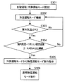
In the dehumidifying operation mode, since the refrigeration capacity is controlled to be low, if the set temperature is greatly reduced with respect to the room temperature, or if the outdoor temperature rises and the amount of heat entering the room increases, It is necessary to shift to the operation mode. However, it is necessary to minimize the transition from the cooling operation mode to the reheat dehumidification mode in order to suppress the occurrence of spraying and fan condensation. When it is determined that the transition is possible by the determination method shown in FIG. Only the dehumidifying operation mode is shifted to the cooling operation mode.
[0022]
FIG. 2 is a control flow in the case of shifting from the dehumidifying operation mode to the cooling operation mode. In FIG. 2, automatic operation is started in step S201, and the operation is continued by being automatically set to the reheat dehumidifying operation mode (step S202). During operation, the room temperature and the outdoor temperature are constantly sampled by the suction sensor and the outdoor temperature sensor. When the outdoor temperature rises, a sufficient effect of lowering the room temperature cannot be expected in the dehumidifying operation mode due to a decrease in the refrigerating capacity and an increase in the amount of heat entering the room.
[0023]
The outdoor temperature at this time is set as an outdoor temperature threshold value K1, and as an example, K1 = 30 ° C. is set. The sampled outdoor air temperature exceeds the threshold value K1 (step S203), and the indoor air temperature is K2deg or more (that is, the indoor air temperature-remote controller setting temperature ≧ K2) continues for t2 minutes or more with respect to the remote control set temperature. When it is operated (step S204), it is determined that the dehumidifying operation mode can be shifted to the cooling operation mode, and an instruction for the cooling operation mode is issued (step S205).
[0024]
K2 and t2 can have a plurality of combinations. For example, (K2, t2) = (3 deg, 10 min) or (K1, t2) = (5 deg, 0 min) is set.
(Embodiment 2)
The control of the second embodiment will be described with reference to FIG.
[0025]
When operating in the cooling operation mode with automatic operation, if the room temperature approaches the remote control set temperature or the outdoor air temperature decreases, it switches to the dehumidification operation mode. If it shifts, it becomes easy to generate spray and fan condensation. Therefore, in the present embodiment, the transition from the cooling operation mode to the reheat dehumidification operation mode is not performed, and the transition to the normal dehumidification operation mode is performed.
[0026]
FIG. 3 is a control flow when shifting from the cooling operation mode to the dehumidifying operation mode. After the start of automatic operation (step S301), when the cooling operation mode is set by the operation shown in the first embodiment (step S302), the cooling operation mode has a large refrigerating capacity, so that the room temperature gradually decreases and the remote controller Approaching the set temperature. Furthermore, the outside air temperature decreases with the passage of time, the outdoor air temperature falls below the threshold value K3 (step S303), and the indoor air temperature is equal to or less than K4 deg with respect to the remote controller set temperature (that is, the indoor air temperature minus the remote controller set temperature ≦ K4). When the operation is continued for more than a minute (step S304), an instruction to shift to the dehumidifying operation mode is issued (step S305). When the instruction is to shift from the cooling operation mode to the dehumidifying operation mode, the reheat dehumidification is performed. The normal dehumidifying operation mode is instructed instead of the operation mode. As an example, K3 = 25 ° C. and (K4, t4) = (3 deg, 10 min) are set.
(Embodiment 3)
The control according to the second embodiment will be described with reference to FIG.
[0027]
FIG. 4 is a control flow in the case of shifting from the cooling operation mode to the dehumidifying operation mode. Steps S401 to S405 are the same as those in the third embodiment. That is, the cooling operation mode is set in the automatic operation (steps S401 and S402), the outdoor temperature falls below the threshold value K3 (step S403) while the cooling operation is continued, and the indoor air temperature is K4 deg or less with respect to the remote control set temperature. When the operation is continued for more than t4 minutes (ie, room temperature-remote controller set temperature ≦ K4) (step S404), an instruction to shift to the dehumidifying operation mode is issued (step S405).
[0028]
In this case, depending on the operating conditions up to that point, there may be cases where spraying or fan condensation does not occur even when the reheat dehumidifying operation mode is entered. The cooling operation state with a high sensible heat ratio corresponds to this, specifically, the case where the room temperature continues to be stable, the compressor is operated at a low speed, and the air volume of the indoor fan is large.
[0029]
FIG. 5 is a region diagram that satisfies such conditions. Region A is a region where reheat dehumidification operation can be transferred, and region B is a region where transfer is not possible.
[0030]
When an instruction to shift to the dehumidifying operation mode is issued in step S405, if the previous operating state has continued for t5 minutes or longer in the A region (step S406), an instruction to shift to the reheat dehumidifying operation mode is issued. (Step S407), otherwise, it is an instruction to shift to the normal dehumidifying operation mode (Step S408).
[0031]
【The invention's effect】
As is apparent from the above embodiment, in the automatic operation in which the operation mode is automatically selected according to the operation conditions, the outside air temperature exceeds a predetermined threshold value, and the room temperature becomes the remote controller set temperature. On the other hand, if the operation duration time is greater than or equal to the specified value, it is determined that it is possible to switch from the dehumidifying operation mode to the cooling operation mode, thereby preventing frequent switching between the cooling mode and the dehumidifying mode, including the amount of leakage heat. By shifting to the cooling mode only when the indoor heat load is kept high, the transition from the cooling mode to the dehumidifying mode can be kept to the minimum necessary, and spraying and fan condensation can be suppressed.
[0032]
In the present invention, in automatic operation, when shifting from the cooling operation mode to the dehumidification operation mode, the transition to the reheat dehumidification operation mode is prohibited, and the transition to the normal dehumidification operation mode is performed to prevent spraying and fan condensation. It becomes possible to do.
[0033]
In the present invention, in the automatic operation, when shifting from the cooling operation mode to the dehumidifying operation mode, the cooling operation is continued in a state where the sensible heat ratio is high until then, and even if the reheat dehumidifying operation mode is switched, When the compressor is operated at a low speed and the indoor fan is operating at a large airflow, and the airflow of the indoor fan is continued for a predetermined value or more, it is considered that there is no fan condensation. This makes it possible to prevent spraying and fan condensation while making maximum use of the reheat dehumidifying operation mode that allows isothermal dehumidification and warm dehumidification in automatic operation. .
[Brief description of the drawings]
FIG. 1 is a configuration diagram of a refrigeration cycle of an air conditioner according to the present invention. FIG. 2 is a flowchart showing a first embodiment of the invention. FIG. 3 is a flowchart showing a second embodiment of the invention. FIG. 5 is a flow chart showing the third embodiment. FIG. 5 is an explanatory diagram of a control table showing the third embodiment of the invention.
DESCRIPTION OF
Claims (3)
Priority Applications (1)
| Application Number | Priority Date | Filing Date | Title |
|---|---|---|---|
| JP2000300113A JP4134501B2 (en) | 2000-09-29 | 2000-09-29 | Automatic operation control method for air conditioner |
Applications Claiming Priority (1)
| Application Number | Priority Date | Filing Date | Title |
|---|---|---|---|
| JP2000300113A JP4134501B2 (en) | 2000-09-29 | 2000-09-29 | Automatic operation control method for air conditioner |
Publications (2)
| Publication Number | Publication Date |
|---|---|
| JP2002106913A JP2002106913A (en) | 2002-04-10 |
| JP4134501B2 true JP4134501B2 (en) | 2008-08-20 |
Family
ID=18781835
Family Applications (1)
| Application Number | Title | Priority Date | Filing Date |
|---|---|---|---|
| JP2000300113A Expired - Fee Related JP4134501B2 (en) | 2000-09-29 | 2000-09-29 | Automatic operation control method for air conditioner |
Country Status (1)
| Country | Link |
|---|---|
| JP (1) | JP4134501B2 (en) |
Families Citing this family (11)
| Publication number | Priority date | Publication date | Assignee | Title |
|---|---|---|---|---|
| JP3997127B2 (en) * | 2002-08-29 | 2007-10-24 | 東芝キヤリア株式会社 | Air conditioner |
| US20110146306A1 (en) * | 2008-10-02 | 2011-06-23 | Taras Michael F | Start-up for refrigerant system with hot gas reheat |
| JP5381062B2 (en) * | 2008-12-09 | 2014-01-08 | パナソニック株式会社 | Air conditioner |
| CN104165443B (en) * | 2014-08-12 | 2016-08-31 | 珠海格力电器股份有限公司 | Air conditioning unit mode conversion control method and device and air conditioning system |
| JP6925461B2 (en) * | 2016-08-25 | 2021-08-25 | 三菱電機株式会社 | Air conditioners, air conditioners and programs |
| CN108507125B (en) * | 2018-01-23 | 2020-12-18 | 青岛海尔空调电子有限公司 | A compound mode control method for an air-conditioning unit |
| CN108332380B (en) * | 2018-01-29 | 2020-11-27 | 青岛海尔空调电子有限公司 | Air-cooled magnetic levitation air conditioning unit and its control method |
| CN108709306A (en) * | 2018-05-05 | 2018-10-26 | 黄永培 | Heat-exchange system and air-conditioning system |
| JP7532761B2 (en) * | 2019-11-07 | 2024-08-14 | 株式会社富士通ゼネラル | Air conditioners |
| CN113819621B (en) * | 2021-08-17 | 2023-04-18 | 青岛海尔空调器有限总公司 | Method and device for controlling operation of air conditioner and air conditioner |
| CN114719335B (en) * | 2022-05-10 | 2023-06-06 | 珠海格力电器股份有限公司 | Air conditioner cleaning method |
-
2000
- 2000-09-29 JP JP2000300113A patent/JP4134501B2/en not_active Expired - Fee Related
Also Published As
| Publication number | Publication date |
|---|---|
| JP2002106913A (en) | 2002-04-10 |
Similar Documents
| Publication | Publication Date | Title |
|---|---|---|
| EP2719966B1 (en) | Refrigeration air-conditioning device | |
| CN101749885B (en) | Refrigeration apparatus | |
| JP4134501B2 (en) | Automatic operation control method for air conditioner | |
| CN103292527A (en) | Air conditioning device | |
| WO2010039385A2 (en) | Start-up for refrigerant system with hot gas reheat | |
| JP2002089933A (en) | Control device for air conditioner | |
| JP4258117B2 (en) | Air conditioner | |
| KR100772217B1 (en) | How to control the air conditioner | |
| JP2013002749A (en) | Air conditioning device | |
| KR100504478B1 (en) | Indoor unit for air conditioner | |
| JP6755396B2 (en) | Air conditioner | |
| JP2005291553A (en) | Multi-type air conditioner | |
| KR20190081837A (en) | air-conditioning system | |
| JP4074422B2 (en) | Air conditioner and its control method | |
| JP2001147052A (en) | Air conditioner | |
| JP6551437B2 (en) | air conditioner | |
| JP7783480B2 (en) | Refrigeration cycle equipment | |
| US20060207273A1 (en) | Method of controlling over-load cooling operation of air conditioner | |
| JP2002286273A (en) | Air conditioner | |
| JPH0718933Y2 (en) | Release controller for air conditioner | |
| CN110145892B (en) | Defrosting system of air conditioner and control method thereof | |
| JPH10300254A (en) | Air conditioner | |
| JP6628972B2 (en) | Air conditioning system control device, air conditioning system, air conditioning system control program, and air conditioning system control method | |
| JP4572470B2 (en) | Operation control method of air conditioner | |
| CN118856447B (en) | Air conditioning system and control method thereof |
Legal Events
| Date | Code | Title | Description |
|---|---|---|---|
| A621 | Written request for application examination |
Free format text: JAPANESE INTERMEDIATE CODE: A621 Effective date: 20040909 |
|
| RD01 | Notification of change of attorney |
Free format text: JAPANESE INTERMEDIATE CODE: A7421 Effective date: 20050630 |
|
| A131 | Notification of reasons for refusal |
Free format text: JAPANESE INTERMEDIATE CODE: A131 Effective date: 20070911 |
|
| A521 | Written amendment |
Free format text: JAPANESE INTERMEDIATE CODE: A523 Effective date: 20071017 |
|
| TRDD | Decision of grant or rejection written | ||
| A01 | Written decision to grant a patent or to grant a registration (utility model) |
Free format text: JAPANESE INTERMEDIATE CODE: A01 Effective date: 20080507 |
|
| A01 | Written decision to grant a patent or to grant a registration (utility model) |
Free format text: JAPANESE INTERMEDIATE CODE: A01 |
|
| A61 | First payment of annual fees (during grant procedure) |
Free format text: JAPANESE INTERMEDIATE CODE: A61 Effective date: 20080520 |
|
| FPAY | Renewal fee payment (event date is renewal date of database) |
Free format text: PAYMENT UNTIL: 20110613 Year of fee payment: 3 |
|
| FPAY | Renewal fee payment (event date is renewal date of database) |
Free format text: PAYMENT UNTIL: 20120613 Year of fee payment: 4 |
|
| FPAY | Renewal fee payment (event date is renewal date of database) |
Free format text: PAYMENT UNTIL: 20130613 Year of fee payment: 5 |
|
| LAPS | Cancellation because of no payment of annual fees |