JP4134560B2 - Linear motor and stage device - Google Patents
Linear motor and stage device Download PDFInfo
- Publication number
- JP4134560B2 JP4134560B2 JP2002007227A JP2002007227A JP4134560B2 JP 4134560 B2 JP4134560 B2 JP 4134560B2 JP 2002007227 A JP2002007227 A JP 2002007227A JP 2002007227 A JP2002007227 A JP 2002007227A JP 4134560 B2 JP4134560 B2 JP 4134560B2
- Authority
- JP
- Japan
- Prior art keywords
- flow path
- linear motor
- housing
- magnet
- refrigerant
- Prior art date
- Legal status (The legal status is an assumption and is not a legal conclusion. Google has not performed a legal analysis and makes no representation as to the accuracy of the status listed.)
- Expired - Fee Related
Links
Images



Landscapes
- Linear Motors (AREA)
- Exposure And Positioning Against Photoresist Photosensitive Materials (AREA)
- Container, Conveyance, Adherence, Positioning, Of Wafer (AREA)
- Exposure Of Semiconductors, Excluding Electron Or Ion Beam Exposure (AREA)
- Motor Or Generator Cooling System (AREA)
Description
【0001】
【発明の属する技術分野】
本発明は、リニアモータ及びそれを用いたステージ装置に関するものである。
【0002】
【従来の技術】
近年、半導体装置のパターンのさらなる微細化が求められることによって、半導体製造装置、例えば、前記パターンをウエハ上に露光するための露光装置等においては、精度に関する要求が一層厳しいものとなっている。このような露光装置に搭載されるステージ装置には、nmオーダーの位置決め精度が必要とされる。
【0003】
前記ステージ装置の駆動部に用いられるリニアモータは、気体軸受(例えば空気軸受)と共にステージ移動での摩擦を大幅に排除できることで、位置決め精度の向上に貢献してきた。しかし、複数のコイルからなるリニアモータの電機子は、発熱体として周囲に与える温度影響があるため、位置決め精度を確保するに冷媒を用いて強制冷却をしていた。この冷媒を用いた冷却は、複数のコイルをハウジングで覆って電機子を構成し、ハウジング内部に冷媒を流すことにより複数のコイルを冷却して電機子の温度上昇を抑えるものである。
【0004】
また、前述の半導体露光装置には、高い精度と共に高いスループットが求められており、この半導体露光装置に搭載されるステージ装置には高制御性、高加速度、高速度、長いストロークなどが求められてきた。従って、半導体露光装置のステージ装置の駆動に用いられるリニアモータにも同様の性能が必要とされている。特に高加速度を必要とされる場合には、可動部の質量を小さくすると共に、リニアモータの推力を大きくすることが重要となる。推力を大きくするためには、磁束密度の高い永久磁石を使う、コイルの巻数を多くする、コイルへ通す電流を大きくするなどの方法がある。しかしながら、永久磁石においてはコスト、減磁などの観点から選べる磁石が限定され、また、コイルへの電流値もアンプなどの制御装置から限定される。したがって、一般的にはコイルの巻数を増やすことで対処される。
このようなリニアモータでは、コイルからの発熱量が増大するために冷媒の流量を増やすことになるが、内部の圧力が大きくなってハウジングが変形し、永久磁石と接触してしまうという問題が発生する。また、予め変形を考慮して永久磁石とハウジングとの空隙を大きくするとモータ効率が下がってしまい、大きな推力を出すためには大電流が必要となるという問題が発生する。
【0005】
内部の圧力が大きくなっても変形し難いハウジング形状としては、円筒形状のものがあり、特開2001−218443号公報には、電機子のハウジング形状が円筒形であるリニアモータが開示されている。特開2001−218443号公報に開示されているリニアモータは、円柱形の永久磁石を丸管の中に多数配置して両端をブロックにより封じ込めて固定子を構成し、この丸管の一部分を囲む円筒形ハウジングに円筒コイルを多数内包して可動子を構成している。以下、この型のリニアモータをシャフト型リニアモータと称する。
【0006】
シャフト型リニアモータには、円筒コイルを丸管の中に多数配置して両端をブロックにより封じ込めて固定子を構成し、この丸管の一部分を囲む円筒形ハウジングに円筒形の永久磁石を多数内包して可動子を構成するものもある。
【0007】
図9は、ムービングコイルタイプのシャフト型リニアモータの構造を示す斜視図であり、円筒形の永久磁石からなる固定子10と、複数の円筒コイルからなる可動子20とから構成されている。
【0008】
可動子20は、複数の円筒コイルと、この複数の円筒コイルを覆うハウジングとの間に冷却用の流路が設けられている。可動子20の両端には冷媒の導入口20aと排出口20bとが設けられている。
【0009】
図9のシャフト型リニアモータで大推力に対応するには、円筒コイルの周方向に巻数を増やすことは永久磁石から離れる方向になるので得策ではなく、円筒コイルを永久磁石の配列方向に増やすことになる。このことは可動子20の全長が長くなることを意味する。
【0010】
【発明が解決しようとする課題】
上記のようなシャフト型リニアモータの場合、可動子20が長くなることによって製造が難しくなり、形状精度や組立精度が下がってしまう。コイル・アセンブリの真直度や同心度、ハウジングの真直度や同心度、そして、コイル・アセンブリとハウジングとの位置決め精度などである。これらの精度の悪化は、冷媒流路の不均一をもたらす。したがって、円筒コイルの冷却でバラツキが生じるため、ハウジング表面の温度は一様にならず、場所による温度ムラを生み出す。
【0011】
このようなハウジングでの温度ムラは、リニアモータのみならず、可動子20の周囲に良からぬ影響を与える。特に、部分的な温度ムラがあると空気の揺らぎが発生するため、ステージの移動距離を計測する光干渉式測長計においては光路変化による計測誤差を生じてしまう。前述のようにnmオーダーの位置決め精度を要求されるステージ装置においては無視できない計測誤差となってしまう。特に、可動子20が長く、移動距離も長い場合においてはなおさらである。このため、このようなリニアモータを用いたステージ装置においては、温度ムラに起因して位置決め精度が劣化してしまうという問題点があった。
【0012】
そこで本発明は、ハウジング表面の温度ムラを無くすことによって、制御性の高いリニアモータを提供することと、並びにこのリニアモータを用いることにより、大推力を必要とされる高加速度の移動であっても、位置決め精度の高いステージ装置を提供することを目的とする。
【0013】
【課題を解決するための手段】
上記目的のために、一実施例を表す図に対応つけて説明すると、請求項1記載のリニアモータは、磁石(11)と、ハウジング(23)に覆われたコイル(21)とを有するリニアモータであって、ハウジング(23)が第1流路(20a)と、コイル(21)からみて第1流路(20a)の外側に形成され、この第1流路(20a)とは独立した第2流路(20b)と有し、第1流路(20a)を流れる第1冷媒の圧力と、第2流路(20b)を流れる第2冷媒の圧力とを異ならせる制御装置(100)を備えている。
【0014】
請求項2記載のリニアモータは、制御装置(100)が、第1流路を流れる第1冷媒の方向と、第2流路を流れる第2冷媒の方向とを異ならせている。請求項3記載のリニアモータは、第1冷媒と第2冷媒とが異なる冷媒である。
【0015】
請求項4記載のリニアモータは、ハウジング(23)の外側の一部に第1流路(20b)と第2流路(20b)とは異なる第3流路(37)を設けている。請求項5記載のリニアモータは、磁石(11)の温度を制御するための流体が流れる第4流路(20c)を備え、第4流路は磁石によって周囲を囲まれている。
【0016】
請求項6記載のリニアモータは、第4流路(20c)とは独立し、磁石(11)を内包するように形成された第5流路(20d)を有している。請求項7記載のリニアモータは、磁石(11)が円筒形状の磁石であり、第4流路(20d)は、円筒形状の磁石(11)の空洞部に挿入された非磁性体の管状部材(13)によって形成されている。
【0017】
請求項8記載のリニアモータは、第1流路(20a)と第2流路(20b)とのいずれか一方が磁石(11)に連通する連通部(20h)を備えている。
請求項9記載のステージ装置は、試料を保持して移動するステージ(4)を備えたステージ装置であって、請求項1から8のいずれか1項記載のリニアモータを用いてステージ(4)を駆動している。
【0018】
【発明の実施の形態】
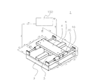
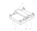
本発明の実施の形態について図を用いて説明する。図1は、ステージ装置1の構造を示す斜視図である。このステージ装置1は、1軸移動の装置で、石定盤もしくはセラミックなどからなるベース3と、試料(例えばパタ−ンを有したマスク)を保持してベース3上を移動可能なテーブル4(ステージ)とを有している。テーブル4は、気体軸受けである空気軸受5を用いて、ベース3に形成された案内6に沿って移動するものであり、このテーブルの移動には、ベースに設けられた固定子10と、テーブル4に固定された移動子20とを有する2組のシャフト型リニアモータが用いられている。なお、制御装置100は、ステージ装置1全体を制御するものであり、本実施例においては、特に固定子10の冷却を制御している(詳細は後述)。
【0019】
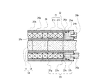
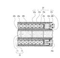
図2は、固定子10と移動子20とを有するシャフト型リニアモータの断面を表す図であり、以下、この図2に沿ってシャフト型リニアモータの構成を更に説明する。
【0020】
固定子10は、非磁性の円筒状部材(丸管)12に多数の永久磁石11を内包して不図示の両端のブロックを用いて多数の永久磁石11を封じ込めている。永久磁石11は、円柱形をしており、同極同士が向き合う形で円筒状部材12内に配置される。また、図示していないが、同極の磁石の間にポールピースとして円柱形の磁性体を挟むことにより、組込時の磁石同士の反発力を和らげることができる。磁石と磁石、あるいは磁石とポールピースとは接着剤によって固着され、円筒状部材12の両端をそれぞれ非磁性のブロック(不図示)に固定することにより、磁石列を保持している。
【0021】
可動子20は、大別すると、コイル組立体21と、コイル支持体22と、コイル組立体21を取り囲むハウジング23とから構成される。
コイル組立体21は、円筒形状であり、円筒状部材12と略同心状の円筒管に複数の円筒コイルを有した円筒コイル21cと、円筒コイル21cを一体的に固定している非磁性且つ非導電体製の外皮21sとからなる。円筒コイル21cを構成するコイル単体は、絶縁被膜電線(エナメル線)によって構成され、円周方向と長さ方向に多段多列に巻回された円筒形状をしている。この絶縁被膜電線は丸線であっても角線であってもよい。一本の電線で多段多列に形成する必要はなく、複数の線で構成して結線し、多段多列に形成してもよい。このコイル単体の長さは、複数の永久磁石11によって形成される磁極ピッチによって決まる。コイル単体の長さが決まっている場合、リニアモータの推力を大きくするために巻数を多くしようとすれば電線の線径を細くすることになるが、抵抗値が大きくなって好ましくない。線径と巻数とは磁気設計と電気設計との最適値によって決定される。コイル数は必要とされるリニアモータの推力により決定される。このため、大きな推力が必要であれば多くのコイル単体を必要とする。円筒コイル21cは、コイル単体の内周部分を揃えて端面部分を密着し、非磁性且つ非導電体製の外皮21sによって一体化されている。その際、各コイル間を電気的に結線しておく必要がある。最終的には、コイル組立体21の端面側若しくは両端面側からコネクター(不図示)に接続される線のみが出ている。
【0022】
非磁性且つ非導電性の外皮21sの材料としては、樹脂やセラミックが用いられる。成形用金型を用いて、コイル集合体の周囲に直接外皮を形成する、あるいは、予め用意しておいた外皮にコイル集合体を接着剤によって固定するなどの方法により一体化される。
【0023】
コイル支持体22は、コイル組立体21を位置決めしてハウジング23に固定するためのブロックであり、コイル組立体21の両端面のそれぞれに配置されている。コイル支持体22はコイル組立体21側においては組立体端面の一部とこの端面近傍の内周面あるいは外周面の一部とに当接して接着固定される。当接箇所を一部にしているのは、後述の流体の通路(流路)を多く確保するためである。なお、コイル支持体22は、非磁性且つ非導電性の樹脂やセラミックが望ましいが、低導電性且つ非磁性の金属材であっても構わない。
【0024】
ハウジング23は、本実施例においては、互いに同心円状に位置して径の異なる三つの丸管(以下、内管23u,中管23n,外管23gという)と、内管23uと中管23nと外管23gとの長手方向両端を保持する少なくとも二つ以上のブロック(右蓋23rと不図示の左蓋)とで構成される。不図示の左蓋は、不図示であるが、構造としては右蓋23rと同じである。これらハウジング23を構成する部材には、低導電性且つ非磁性の金属材、非磁性且つ非導電性の樹脂やセラミックを用いることができる。金属部材同士の結合には、強度、密閉性から溶接が望ましいが、接着やカシメ、ネジによる締結であっても構わない。金属以外の部材の結合には接着やネジなどが用いられる。図2では、内管23uと外管23gは溶接で右蓋23rに固定されており、中管23nはOリング24aに接しながら接着剤25aによって固定されている。
【0025】
コイル組立体21とコイル支持体22との位置関係については上述の通りであり、以下、コイル支持体22とハウジング23との位置関係について説明する。コイル支持体22はコイル組立体21の両端にそれぞれ固定されている。コイル組立体21の内周あるいは外周に当接しているコイル支持体22の裏側は、ハウジング23の内管23uの外周あるいは中管23nの内周に当接してラジアル方向の位置決めとなっている。また、コイル組立体21の端面に当接しているコイル支持体22の裏側は、ハウジング23の右蓋23r、左蓋にそれぞれ当接してスラスト方向の位置決めとなっている。
【0026】
したがって、可動子20の組立では、右蓋23rと不図示の左蓋との一方の蓋が既に付けられている筒に、コイル支持体22が固定されているコイル組立体21を挿入し、コネクターへの配線を行ってから、他方の蓋をコイル支持体22に当接させて溶接あるいは接着固定し、管に結合させて完成させる。
【0027】
右蓋23r、左蓋にはハウジング23に流体を導入および排出するための配管口、さらにはコイルへ電流を流すためのコネクターが配置される。図2に示す右蓋23rには、二系統の通路20a,20b(以下、第1の通路20a、第2の通路20bという)に対応する配管口26a,26bが設けてある。なお、配管口26a,26bは、Oリング24bによりシールされている。
【0028】
第1の通路20aは、内管23u、中管23n、右蓋23r、及び不図示の左蓋によって形成されている。一方、第2の通路20bは、中管23n、外管23g、右蓋23r及び不図示の左蓋によって形成されている。この第1の通路20aと第2の通路20bとは独立しており、ハウジング23内で交わることはない。なお、第1の通路20aと第2の通路20bとに供給する冷媒としては、不活性冷媒が好ましく、液体でも気体でもかまわない。また、第1の通路20aと第2の通路20bとに同じ冷媒を流してもいいし、熱の吸収効率が異なる冷媒を流してもかまわない。
【0029】
上記のようなに構成されたシャフト型リニアモータの固定子10の制御装置100による冷却動作について以下説明する。
制御装置100は、第1の通路20aと第2の通路20bで冷媒の流れる方向を逆にすることにより、ハウジング23表面の温度ムラを抑える(図1に矢印で示す流路を参照)。
【0030】
具体的には、図2において、制御装置100は、第1の通路20aにおいて不図示の左蓋に設けられた配管口より冷媒を流し込み、右蓋23rに設けられた配管口26aより冷媒を排出するように制御する。すなわち第1の通路20aでの冷媒の流れは図2の左側から右側になる。このため、冷媒は配管口26aに近づくに連れて温度が高くなっており、内管23uと中管23nの表面温度は図2の右側になるにつれ高くなる。
【0031】
一方、制御装置100は、第2の通路20bにおいては右蓋23rに設けられた配管口26bより冷媒を流し込み、不図示の左蓋に設けられた配管口より冷媒を排出するように制御する。すなわち第2の通路20bでの冷媒の流れは図2の右側から左側にする。中管23nの表面温度の高い方から冷媒を流すことによって、ハウジング23内の温度勾配が小さくなり、外管23gの表面温度を均一にすることができる。
【0032】
このため、図1のステージ装置1のように可動子10が長くても温度ムラが生じることがないので、周囲に与える熱的影響は小さく、且つ大きな推力を発生できるので、テーブル4の高加速移動と精密な位置決めが可能である。
【0033】
また、第1の通路20aと第2の通路20bとで導入する流体の種類を変えるてみてもいい。第1の通路20aには冷却効率の高い物質を流しこみ、第2の通路には断熱性の高い物質20bを流し込む。あるいは、第2の通路20bを真空にしても断熱性が得られるのでそれでも構わない。第2の通路20bに通じる配管口26bは、断熱性の物質を流し込んだ後、常時開いている必要はない。このため、中管23nに温度勾配があっても、断熱性の高い物質により外管23g表面の温度は均一に保たれる。
【0034】
また、制御装置100は、第1の通路20aに流す流体圧と、第2の通路20bに流す流体圧とを同じ圧力に設定してもいいし、ハウジング23の変形を小さくするために、第1の通路20aに流す流体の圧力を第2の通路20bに流す流体の圧力よりも大きく設定してもいい。
【0035】
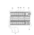
図3は、図1のステージ装置1のシャフト型リニアモータの第2実施例を示す断面図である。図3において、図2と同様の部材には同じ符号をつけその説明を省略する。
【0036】
第2実施例においては、固定子10に対向する面にも第2の通路20bが形成されるように、ハウジング23に新たに丸管23iを設けている。さらに、図2の第1実施例と異なる点は、第1実施例の右蓋23rを右内蓋23r1と右外蓋23r2とに分けたことである。、同様に不図示の左蓋も左内蓋(不図示)と左外蓋(不図示)に分けている。
【0037】
第2実施例のハウジング23は、内管23uと中管23nとからなる第1円筒管を左外蓋と右外蓋33r2によって位置決めして保持している。このため、第1円筒管にコイル組立体31とコイル支持体32を封じ込めた後に、外管23gと丸管23iとからなる第2円筒管に第1の円筒管を封じ込めている。
【0038】
制御装置100は、固定子10と可動子20とのそれぞれを異なる方向から冷却して、ハウジング23表面の温度を均一にしている。
また、制御装置100は、第1の通路20aに流す流体圧を高くし(例えば100MPa)、第2の通路20bに流す流体圧をそれよりも下げることにより(例えば80MPa)、ハウジング23の変形を小さくすることができる。この結果として、冷媒の流量を増やすことができるので、コイル組立体21の発熱を更に抑えることができる。
【0039】
本第2実施例によれば、固定子10に対向する面の温度ムラもなくすことができる。
図4は、シャフト型リニアモータの第3実施例を示す断面図である。図4において、図3と同様の部材には同じ符号をつけその説明を省略する。
【0040】
第3実施例は、第2実施例で説明したハウジング23の表面の一部にヒートパイプ37を配置している。ヒートパイプ37内に冷媒を流すことにより、その周囲を冷やすことができる。組立が完了した可動子10に電流を流すとともに冷媒を流してハウジング23の温度計測を行う。通路の不均一などが原因でハウジング23表面の一部に温度の高いところがあった場合に、ヒートパイプ37を接着剤25aなどにより固定する。前述したように、ヒートパイプ37内に冷媒を流すことによって、ハウジング23表面の温度ムラを無くすことができ、高い位置決め精度を有したステージ装置1を実現することができる。
【0041】
図5は、シャフト型リニアモータの第4実施例を示す断面図である。図5において、図3と同様の部材には同じ符号をつけその説明を省略する。なお、図5においては、第1の通路20aの配管口26aの代わりに電流導入のためのコネクター28の一部を示している。第1の通路20aの配管口26aは不図示であるが、同一面の他の場所に存在する。
【0042】
本第4実施例は、永久磁石11として円筒の永久磁石を用いており、この円筒の永久磁石11の空洞部に非磁性のパイプ13を配置し、さらに円筒の永久磁石11を非磁性の円筒状部材12に挿入して両端をそれぞれ非磁性のブロック(不図示)で固定している。さらに、不図示のブロックにそれぞれ配管口を設け、非磁性のパイプ13の内部と配管口とを連通させることにより、固定子10の中心軸に流体用の通路(以下、第3の通路20cという)を形成している。したがって、第3の通路20cに冷媒を流すことにより、固定子10の温度を均一にすることができる。このため、可動子20からの熱などによって固定子10内の円筒の永久磁石11の温度が変わり、磁束密度に変化を生じてリニアモータの推力が変動するのを防ぐことができる。
【0043】
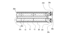
図6は、シャフト型リニアモータの第5実施例を示す断面図であり、図5で説明した固定子10の冷却に更に第4の通路20dを設けた場合の構成を示す断面図である。
【0044】
円筒の永久磁石11を内包し両端を不図示のブロックに溶接された円筒状部材12を、C字形状に曲げられた長尺の非磁性薄板で覆い、継ぎ目を溶接して丸管30として第4の通路20dを形成している。第3の通路20c用の配管口36aがブロック35rにねじ込んであり、その配管口36aの外周のネジを使って第4の通路用の配管口36bが固定されている。24C,24dはOリングである。
【0045】
この第4の通路20dには冷媒や断熱性物質を流すことにより、可動子20からの熱的影響を受けないようにすることができる。なお、第3の通路20cと第4の通路20dとは独立しており、互いが交わることはない。また、制御装置100は、第3の通路20cに冷媒を流す方向に対して第4の通路20dに冷媒を流す方向を逆方向に設定している。
【0046】
図7は、ステージ装置1の変形例であるステージ装置2を示す図であり、図1と同様の構成には同じ符号を付している。
この変形例においては、固定子10に案内機構を持たせるとともに、可動子20に空気軸受けを設けることにより、図1の空気軸受5と案内6を省略した構成となっている。以下、図8を用いて詳細を説明する。なお、図8において、図3と同様の部材には同じ符号をつけその説明を省略する。
【0047】
図8の丸管23iは、数ヶ所に第2の通路20bに貫通する孔20h(連通部)を設けている。そして、右外蓋23R2の配管口26bと不図示の左外蓋の配管口とから空気を導入し、数ヶ所の孔20hから空気を吹き出すことにより、固定子10に対する空気軸受を構成している。このため、数ヶ所の孔20hは、可動子20の冷却のみならず、固定子10と連通し空気軸受を構成することができ、ひいてはステージ装置2の構造を簡単にすることができる。
【0048】
なお、本実施の形態では、シャフト型リニアモータを例にして説明したが、リニアモータ全般において本実施の形態ができることはいうまでもない。また、本実施の形態はムービングコイルタイプに限定されるものではなく、ムービングマグネットタイプにも適用できる。さらに、ステージ装置1,2を2次元に移動するものとしてもよく、この場合にはウエハステージとして用いることもできる。
【0049】
【発明の効果】
請求項1記載のリニアモータは、制御装置が第1流路を流れる第1冷媒の圧力と第2流路を流れる第2冷媒の圧力とを異ならせているので、冷媒の圧力に起因したハウジングの変形を抑制することができる。
【0050】
請求項2記載のリニアモータは、制御装置(100)が、第1冷媒の流れる方向と第2冷媒の流れる方向とを異ならせているので、ハウジングに温度ムラが生じることがない。このため、コイル数が多く、大推力であっても制御性の高いリニアモータを実現することができる。請求項3記載のリニアモータは、第1冷媒と第2冷媒との選択の自由度を広げることができる。
【0051】
請求項4記載のリニアモータは、ハウジングの一部に温度ムラが生じても、第3流路を用いてハウジングの当該部分を冷却することができる。
請求項5から7記載のリニアモータは、磁石を冷却しているので、ハウジングの温度ムラを一段と抑制することができる。
【0052】
請求項8記載のリニアモータは、連通部を有しているので、リニアモータを駆動源とする装置(例えばステージ装置)の構成を簡単にすることができる。
請求項9記載ステージ装置は、高加速度での移動と高い精度の位置決めが可能となり、このステージを半導体製造装置や検査装置で用いれば、当該装置の精度やスループイットが改良する。
【図面の簡単な説明】
【図1】ステージ装置1の構造を示す斜視図である。
【図2】シャフト型リニアモータの断面を表す図である。
【図3】シャフト型リニアモータの第2実施例を示す断面図である。
【図4】シャフト型リニアモータの第3実施例を示す断面図である。
【図5】シャフト型リニアモータの第4実施例を示す断面図である。
【図6】シャフト型リニアモータの第5実施例を示す断面図である。
【図7】ステージ装置2の構造を示す斜視図である。
【図8】シャフト型リニアモータの変形例を示す断面図である。
【図9】従来のシャフト型リニアモータを表す図である。
【符号の説明】
1、2・・・ステージ装置
10・・・固定子
11・・・永久磁石
12・・・円筒状部材
13・・・非磁性のパイプ
20・・・可動子
20a・・・第1の通路
20b・・・第2の通路
20c・・・第3の通路
20d・・・第4の通路
20h・・・孔
21・・・コイル組立体
21c・・・コイル
22・・・コイル支持体
23・・・ハウジング
23i・・・丸管
37・・・ヒートパイプ
100・・・制御装置[0001]
BACKGROUND OF THE INVENTION
The present invention relates to a linear motor and a stage apparatus using the linear motor.
[0002]
[Prior art]
In recent years, further miniaturization of patterns of semiconductor devices has been demanded, so that requirements for accuracy have become more severe in semiconductor manufacturing apparatuses, for example, exposure apparatuses for exposing the patterns onto a wafer. A stage device mounted on such an exposure apparatus requires positioning accuracy on the order of nm.
[0003]
The linear motor used in the drive unit of the stage device has contributed to the improvement of positioning accuracy by being able to greatly eliminate the friction in moving the stage together with the gas bearing (for example, air bearing). However, since the armature of a linear motor composed of a plurality of coils has a temperature effect on the surroundings as a heating element, forced cooling is performed using a refrigerant to ensure positioning accuracy. In the cooling using the refrigerant, an armature is constituted by covering a plurality of coils with a housing, and the plurality of coils are cooled by flowing the refrigerant inside the housing to suppress the temperature rise of the armature.
[0004]
The above-described semiconductor exposure apparatus is required to have high accuracy and high throughput, and a stage apparatus mounted on the semiconductor exposure apparatus is required to have high controllability, high acceleration, high speed, a long stroke, and the like. It was. Therefore, the linear motor used for driving the stage apparatus of the semiconductor exposure apparatus is required to have the same performance. In particular, when high acceleration is required, it is important to reduce the mass of the movable part and increase the thrust of the linear motor. In order to increase the thrust, there are methods such as using a permanent magnet having a high magnetic flux density, increasing the number of turns of the coil, and increasing the current passed through the coil. However, permanent magnets are limited to magnets that can be selected from the viewpoints of cost, demagnetization, and the like, and the current value to the coil is also limited from a control device such as an amplifier. Therefore, it is generally dealt with by increasing the number of turns of the coil.
In such a linear motor, since the amount of heat generated from the coil increases, the flow rate of the refrigerant increases. However, there is a problem that the internal pressure increases and the housing is deformed and comes into contact with the permanent magnet. To do. In addition, if the gap between the permanent magnet and the housing is increased in consideration of deformation in advance, the motor efficiency decreases, and a problem arises that a large current is required to generate a large thrust.
[0005]
As a housing shape that is not easily deformed even when the internal pressure increases, there is a cylindrical shape, and Japanese Patent Application Laid-Open No. 2001-218443 discloses a linear motor in which the armature housing shape is cylindrical. . In the linear motor disclosed in Japanese Patent Laid-Open No. 2001-218443, a large number of cylindrical permanent magnets are arranged in a round tube, and both ends are enclosed by blocks to form a stator, and a part of the round tube is enclosed. A mover is configured by enclosing a large number of cylindrical coils in a cylindrical housing. Hereinafter, this type of linear motor is referred to as a shaft type linear motor.
[0006]
In a shaft type linear motor, a large number of cylindrical coils are arranged in a round tube and both ends are enclosed by blocks to form a stator. A cylindrical housing surrounding a part of the round tube contains a large number of cylindrical permanent magnets. Some of them constitute a mover.
[0007]
FIG. 9 is a perspective view showing the structure of a moving coil type shaft type linear motor, which is composed of a
[0008]
The
[0009]
In order to cope with a large thrust with the shaft type linear motor of FIG. 9, increasing the number of turns in the circumferential direction of the cylindrical coil is not a good idea because it is in a direction away from the permanent magnet, but increasing the cylindrical coil in the arrangement direction of the permanent magnet. become. This means that the total length of the
[0010]
[Problems to be solved by the invention]
In the case of the above-described shaft type linear motor, the length of the
[0011]
Such temperature unevenness in the housing adversely affects not only the linear motor but also the periphery of the
[0012]
Therefore, the present invention provides a linear motor with high controllability by eliminating temperature unevenness on the surface of the housing, and by using this linear motor, it is a high-acceleration movement that requires a large thrust. Another object of the present invention is to provide a stage apparatus with high positioning accuracy.
[0013]
[Means for Solving the Problems]
For the above purpose, a linear motor according to
[0014]
The linear motor according to
[0015]
The linear motor according to claim 4, wherein the outside of the housing (23).Part ofA third flow path (37) different from the first flow path (20b) and the second flow path (20b) is provided. The linear motor according to
[0016]
The linear motor according to claim 6 is:The fifth channel formed so as to contain the magnet (11) independently of the fourth channel (20c).It has a flow path (20d). The linear motor according to claim 7, wherein the magnet (11) is a cylindrical magnet,Fourth flow path (20d)Of the cylindrical magnet (11)Inserted into the cavityNon-magnetic materialFormed by the tubular member (13)Yes.
[0017]
The linear motor according to claim 8 includes a communication portion (20h) in which one of the first flow path (20a) and the second flow path (20b) communicates with the magnet (11).
The stage apparatus according to claim 9 is a stage apparatus including a stage (4) that holds and moves the sample, and the stage (4) using the linear motor according to any one of
[0018]
DETAILED DESCRIPTION OF THE INVENTION
Embodiments of the present invention will be described with reference to the drawings. FIG. 1 is a perspective view showing the structure of the
[0019]
FIG. 2 is a view showing a cross section of a shaft type linear motor having a
[0020]
The
[0021]
The
The
[0022]
As a material for the nonmagnetic and nonconductive
[0023]
The
[0024]
In this embodiment, the
[0025]
The positional relationship between the
[0026]
Therefore, in assembling the
[0027]
On the
[0028]
The
[0029]
The cooling operation by the
The
[0030]
Specifically, in FIG. 2, the
[0031]
On the other hand, in the
[0032]
For this reason, even if the
[0033]
Moreover, you may try changing the kind of fluid introduce | transduced by the 1st channel |
[0034]
Further, the
[0035]
FIG. 3 is a cross-sectional view showing a second embodiment of the shaft type linear motor of the
[0036]
In the second embodiment, a
[0037]
The
[0038]
The
In addition, the
[0039]
According to the second embodiment, the temperature unevenness of the surface facing the
FIG. 4 is a sectional view showing a third embodiment of the shaft type linear motor. In FIG. 4, the same members as those in FIG.
[0040]
In the third embodiment, a
[0041]
FIG. 5 is a sectional view showing a fourth embodiment of the shaft type linear motor. In FIG. 5, the same members as those in FIG. In FIG. 5, a part of the
[0042]
In the fourth embodiment, a cylindrical permanent magnet is used as the
[0043]
FIG. 6 is a cross-sectional view showing a fifth embodiment of the shaft type linear motor, and is a cross-sectional view showing a configuration when a
[0044]
A
[0045]
By flowing a coolant or a heat insulating material through the
[0046]
FIG. 7 is a view showing a
In this modified example, the
[0047]
The
[0048]
In this embodiment, the shaft type linear motor has been described as an example, but it goes without saying that the present embodiment can be applied to all linear motors. Further, the present embodiment is not limited to the moving coil type, but can be applied to a moving magnet type. Further, the
[0049]
【The invention's effect】
In the linear motor according to
[0050]
The linear motor according to
[0051]
The linear motor according to claim 4 can cool the portion of the housing using the third flow path even if temperature unevenness occurs in a portion of the housing.
In the linear motor according to the fifth to seventh aspects, since the magnet is cooled, the temperature unevenness of the housing can be further suppressed.
[0052]
Since the linear motor according to the eighth aspect has the communication portion, the configuration of the apparatus (for example, a stage apparatus) using the linear motor as a drive source can be simplified.
The stage apparatus according to the ninth aspect can move at high acceleration and can be positioned with high accuracy. If this stage is used in a semiconductor manufacturing apparatus or an inspection apparatus, the accuracy and throughput of the apparatus are improved.
[Brief description of the drawings]
FIG. 1 is a perspective view showing a structure of a
FIG. 2 is a diagram showing a cross section of a shaft type linear motor.
FIG. 3 is a sectional view showing a second embodiment of the shaft type linear motor.
FIG. 4 is a cross-sectional view showing a third embodiment of the shaft type linear motor.
FIG. 5 is a cross-sectional view showing a fourth embodiment of the shaft type linear motor.
FIG. 6 is a cross-sectional view showing a fifth embodiment of the shaft-type linear motor.
7 is a perspective view showing a structure of the
FIG. 8 is a cross-sectional view showing a modification of the shaft type linear motor.
FIG. 9 is a diagram illustrating a conventional shaft type linear motor.
[Explanation of symbols]
1, 2, ... Stage device
10 ... Stator
11 ... Permanent magnet
12 ... Cylindrical member
13. Non-magnetic pipe
20 ... Mover
20a ... 1st passage
20b ... second passage
20c ... third passage
20d ... fourth passage
20h ... hole
21 ... Coil assembly
21c ... Coil
22 ... Coil support
23 ... Housing
23i ・ ・ ・ Round tube
37 ... Heat pipe
100 ... Control device
Claims (9)
前記第1流路を流れる第1冷媒の圧力と、第2流路を流れる第2冷媒の圧力とを異ならせる制御装置を備えたことを特徴とするリニアモータ。In a linear motor having a magnet and a coil covered with a housing, the housing has a first flow path and a first flow path that is formed outside the first flow path as viewed from the coil and independent of the first flow path. Two flow paths,
Linear motor comprising: the pressure of the first refrigerant flowing through the first flow path, a control device to vary the pressure of the second refrigerant flowing through the second flow path.
前記第4流路は、前記円筒形状の磁石の空洞部に挿入された非磁性体の管状部材によって形成されていることを特徴とする請求項5または6記載のリニアモータ。The magnet is a cylindrical magnet,
The linear motor according to claim 5, wherein the fourth flow path is formed by a non-magnetic tubular member inserted into a hollow portion of the cylindrical magnet.
請求項1から8のいずれか1項記載のリニアモータを用いて、前記ステージを駆動することを特徴とするステージ装置。In a stage apparatus equipped with a stage that holds and moves a sample,
A stage apparatus that drives the stage using the linear motor according to claim 1.
Priority Applications (1)
| Application Number | Priority Date | Filing Date | Title |
|---|---|---|---|
| JP2002007227A JP4134560B2 (en) | 2002-01-16 | 2002-01-16 | Linear motor and stage device |
Applications Claiming Priority (1)
| Application Number | Priority Date | Filing Date | Title |
|---|---|---|---|
| JP2002007227A JP4134560B2 (en) | 2002-01-16 | 2002-01-16 | Linear motor and stage device |
Publications (3)
| Publication Number | Publication Date |
|---|---|
| JP2003209962A JP2003209962A (en) | 2003-07-25 |
| JP2003209962A5 JP2003209962A5 (en) | 2005-08-04 |
| JP4134560B2 true JP4134560B2 (en) | 2008-08-20 |
Family
ID=27645791
Family Applications (1)
| Application Number | Title | Priority Date | Filing Date |
|---|---|---|---|
| JP2002007227A Expired - Fee Related JP4134560B2 (en) | 2002-01-16 | 2002-01-16 | Linear motor and stage device |
Country Status (1)
| Country | Link |
|---|---|
| JP (1) | JP4134560B2 (en) |
Families Citing this family (17)
| Publication number | Priority date | Publication date | Assignee | Title |
|---|---|---|---|---|
| WO2005122242A1 (en) * | 2004-06-07 | 2005-12-22 | Nikon Corporation | Stage apparatus, exposure apparatus, and exposure method |
| CN1969445A (en) * | 2004-06-21 | 2007-05-23 | 柯尼卡美能达医疗印刷器材株式会社 | Linear motor and method of producing linear motor |
| US20070234552A1 (en) * | 2004-06-21 | 2007-10-11 | Hajime Nozawa | Method for Manufacturing Linear Motor |
| WO2005124979A1 (en) * | 2004-06-21 | 2005-12-29 | Konica Minolta Medical & Graphic, Inc. | Linear motor and method of producing linear motor |
| WO2006011614A1 (en) * | 2004-07-25 | 2006-02-02 | Tsheatronics Co., Ltd. | Linear or curved mobile motor and its radiator |
| JP4656306B2 (en) * | 2005-05-20 | 2011-03-23 | 株式会社安川電機 | Canned linear motor armature and canned linear motor |
| JP4837993B2 (en) * | 2006-01-06 | 2011-12-14 | 住友重機械工業株式会社 | LINEAR MOTOR, MANUFACTURING METHOD THEREOF, AND STAGE DEVICE USING THE LINEAR MOTOR |
| JP2008048565A (en) * | 2006-08-21 | 2008-02-28 | Murata Mach Ltd | Linear motor and machine tool mounting it |
| KR101206959B1 (en) * | 2006-11-29 | 2012-11-30 | 도쿄엘렉트론가부시키가이샤 | Substrate processing apparatus |
| JP2008193760A (en) * | 2007-01-31 | 2008-08-21 | Tsubakimoto Chain Co | Linear motor |
| JPWO2009041185A1 (en) * | 2007-09-25 | 2011-01-20 | 株式会社安川電機 | Cylindrical linear motor and its stator manufacturing method |
| KR101563380B1 (en) * | 2007-12-28 | 2015-11-06 | 램 리써치 코포레이션 | Wafer carrier drive apparatus and method for operating the same |
| JP5627339B2 (en) * | 2010-08-06 | 2014-11-19 | 富士機械製造株式会社 | Shaft type linear motor |
| JP5832763B2 (en) * | 2011-03-07 | 2015-12-16 | 株式会社ジイエムシーヒルストン | Linear motor |
| JP2013012718A (en) * | 2011-05-27 | 2013-01-17 | Nsk Technology Co Ltd | Proximity exposure device |
| JP6661612B2 (en) * | 2014-08-22 | 2020-03-11 | アンカ・ピーティーワイ・リミテッド | Linear motor |
| KR20250145083A (en) * | 2023-09-06 | 2025-10-13 | 가부시키가이샤 후지 | Linear motor and component mounting machine |
-
2002
- 2002-01-16 JP JP2002007227A patent/JP4134560B2/en not_active Expired - Fee Related
Also Published As
| Publication number | Publication date |
|---|---|
| JP2003209962A (en) | 2003-07-25 |
Similar Documents
| Publication | Publication Date | Title |
|---|---|---|
| JP4134560B2 (en) | Linear motor and stage device | |
| JP5423392B2 (en) | Canned linear motor armature and canned linear motor | |
| US9712030B2 (en) | Shaft rotary type linear motor and shaft rotary type linear motor unit | |
| JP5292707B2 (en) | Moving magnet type linear motor | |
| EP1365498A2 (en) | Voice coil linear actuator, apparatus using the actuator, and method for manufacturing the actuator | |
| US6977451B2 (en) | Ironless AC linear motor | |
| TW200937810A (en) | Cylindrical linear motor, and its stator manufacturing method | |
| WO2004019470A1 (en) | Coreless linear motor | |
| US20060113847A1 (en) | Linear actuator | |
| JP2007097295A (en) | Linear motor and manufacturing method thereof | |
| EP2784920A2 (en) | Linear motor | |
| JP2003032993A (en) | Linear motor | |
| JP2011205878A (en) | Vacuum actuator and substrate transport robot | |
| WO2004091079A1 (en) | Canned linear motor armature and canned linear motor | |
| JP2001286118A (en) | Primary side member for linear dc motor and linear dc motor | |
| CN105659339A (en) | Cooling structure for electromagnetic coil, and electromagnetic actuator | |
| KR100623535B1 (en) | Actuator coil cooling system | |
| JP2013169110A (en) | Cooling structure of linear motor | |
| WO2005011093A1 (en) | Coreless ac linear motor and method of producing the same | |
| JP5369265B2 (en) | Linear motor and linear moving stage device | |
| JP2008259373A (en) | Linear motor | |
| WO2020031657A1 (en) | Linear motor mechanism and two-axis stage | |
| CN219760837U (en) | Cylindrical linear motor | |
| JP2005094902A (en) | Mobile device | |
| JP3268033B2 (en) | Actuator |
Legal Events
| Date | Code | Title | Description |
|---|---|---|---|
| A521 | Written amendment |
Free format text: JAPANESE INTERMEDIATE CODE: A523 Effective date: 20050112 |
|
| A621 | Written request for application examination |
Free format text: JAPANESE INTERMEDIATE CODE: A621 Effective date: 20050112 |
|
| A131 | Notification of reasons for refusal |
Free format text: JAPANESE INTERMEDIATE CODE: A131 Effective date: 20080219 |
|
| A521 | Written amendment |
Free format text: JAPANESE INTERMEDIATE CODE: A523 Effective date: 20080410 |
|
| TRDD | Decision of grant or rejection written | ||
| A01 | Written decision to grant a patent or to grant a registration (utility model) |
Free format text: JAPANESE INTERMEDIATE CODE: A01 Effective date: 20080507 |
|
| A01 | Written decision to grant a patent or to grant a registration (utility model) |
Free format text: JAPANESE INTERMEDIATE CODE: A01 |
|
| A61 | First payment of annual fees (during grant procedure) |
Free format text: JAPANESE INTERMEDIATE CODE: A61 Effective date: 20080520 |
|
| R150 | Certificate of patent or registration of utility model |
Free format text: JAPANESE INTERMEDIATE CODE: R150 |
|
| FPAY | Renewal fee payment (event date is renewal date of database) |
Free format text: PAYMENT UNTIL: 20110613 Year of fee payment: 3 |
|
| A521 | Written amendment |
Free format text: JAPANESE INTERMEDIATE CODE: A523 Effective date: 20080410 |
|
| LAPS | Cancellation because of no payment of annual fees |