JP4134582B2 - Wind power generator - Google Patents
Wind power generator Download PDFInfo
- Publication number
- JP4134582B2 JP4134582B2 JP2002077472A JP2002077472A JP4134582B2 JP 4134582 B2 JP4134582 B2 JP 4134582B2 JP 2002077472 A JP2002077472 A JP 2002077472A JP 2002077472 A JP2002077472 A JP 2002077472A JP 4134582 B2 JP4134582 B2 JP 4134582B2
- Authority
- JP
- Japan
- Prior art keywords
- generator
- value
- rotation
- field current
- wind
- Prior art date
- Legal status (The legal status is an assumption and is not a legal conclusion. Google has not performed a legal analysis and makes no representation as to the accuracy of the status listed.)
- Expired - Fee Related
Links
Images


Classifications
-
- Y—GENERAL TAGGING OF NEW TECHNOLOGICAL DEVELOPMENTS; GENERAL TAGGING OF CROSS-SECTIONAL TECHNOLOGIES SPANNING OVER SEVERAL SECTIONS OF THE IPC; TECHNICAL SUBJECTS COVERED BY FORMER USPC CROSS-REFERENCE ART COLLECTIONS [XRACs] AND DIGESTS
- Y02—TECHNOLOGIES OR APPLICATIONS FOR MITIGATION OR ADAPTATION AGAINST CLIMATE CHANGE
- Y02B—CLIMATE CHANGE MITIGATION TECHNOLOGIES RELATED TO BUILDINGS, e.g. HOUSING, HOUSE APPLIANCES OR RELATED END-USER APPLICATIONS
- Y02B10/00—Integration of renewable energy sources in buildings
- Y02B10/30—Wind power
-
- Y—GENERAL TAGGING OF NEW TECHNOLOGICAL DEVELOPMENTS; GENERAL TAGGING OF CROSS-SECTIONAL TECHNOLOGIES SPANNING OVER SEVERAL SECTIONS OF THE IPC; TECHNICAL SUBJECTS COVERED BY FORMER USPC CROSS-REFERENCE ART COLLECTIONS [XRACs] AND DIGESTS
- Y02—TECHNOLOGIES OR APPLICATIONS FOR MITIGATION OR ADAPTATION AGAINST CLIMATE CHANGE
- Y02E—REDUCTION OF GREENHOUSE GAS [GHG] EMISSIONS, RELATED TO ENERGY GENERATION, TRANSMISSION OR DISTRIBUTION
- Y02E10/00—Energy generation through renewable energy sources
- Y02E10/70—Wind energy
- Y02E10/72—Wind turbines with rotation axis in wind direction
Landscapes
- Wind Motors (AREA)
- Control Of Eletrric Generators (AREA)
- Connection Of Motors, Electrical Generators, Mechanical Devices, And The Like (AREA)
Description
【0001】
【発明の属する技術分野】
本発明は、都市部などでの使用に適した風力発電装置に関する。
【0002】
【従来の技術】
最近では、太陽光発電や風力発電等の小規模で環境汚染を伴わない各種のクリーンな発電システムが実用化されている。その中で、導入時の初期コストが比較的安価な風力発電装置が見直されている。
【0003】
【発明が解決しようとする課題】
ところで、都市部などの一般生活環境下で用いられる風力発電装置は、通常の風量において常時翼を回転させることが難しく、また、一旦翼の回転が停止すると、回転を再開することが難しいという問題があった。このため、発電収支が不足しがちになっている。この原因としては、微風あるいは弱風時には風力エネルギそのものが小さいことや、一旦翼の回転が停止した失速状態では、回転を再開する際に比較的大きな駆動トルクが必要になることなどが考えられる。
【0004】
このような停止した翼の回転を容易にするために、従来は、スタータを用いて翼を風力以外の駆動トルクで回転させたり、軸受け駆動損失を減らして翼が回転しやすくするために強度を犠牲にして翼の軽量化を図ったりしていたが、装置の大型化や装置自体の破損を招くことになるため、実用的な対策とはいえない。
【0005】
本発明は、このような点に鑑みて創作されたものであり、その目的は、停止した翼にかかる負担を低減して容易に回転を開始することができる風力発電装置を提供することにある。
【0006】
【課題を解決するための手段】
上述した課題を解決するために、本発明の風力発電装置は、翼軸の回転に同期して回転する発電機を有しており、この発電機には、翼軸の回転数が第1の値以上であるときに界磁電流の供給を開始する制御を行う制御手段が備わっている。翼軸の回転数が第1の値以上になるまで界磁電流の供給が停止されるため、停止した翼にかかる発電機による負荷を低減することが可能になり、微風あるいは弱風であっても容易に翼の回転を開始することができる。
【0007】
また、上述した制御手段は、界磁電流を流した後に翼軸の回転数が、第1の値よりも小さな第2の値以下に低下したときに界磁電流の供給を停止する制御を行うことが望ましい。一旦、翼が回転を開始すると回転を維持することは比較的容易であり、界磁電流の供給を開始した第1の値よりも回転数が低い第2の値以下に低下するまで界磁電流の供給が維持されるため、発電電力をより多く取り出すことが可能になる。
【0008】
また、上述した発電機は、多相電機子巻線のいずれかの相に現れる電圧に基づいて翼軸の回転数を検出する回転検出手段をさらに備え、制御手段によって一時的な界磁電流の供給を行ったときに、回転検出手段による回転数検出を行うことが望ましい。これにより、簡単な構成によって確実に発電機の回転数を検出することができるとともに、回転数検出のために必要となる負荷を少なくすることができる。
【0009】
また、風力値を測定する風力計をさらに備えるとともに、上述した制御手段は、風力計によって測定した風力値が所定値を超えたときに、回転検出手段による回転数検出のための一時的な界磁電流の供給を行うことが望ましい。これにより、回転数検出のために界磁電流を供給する回数を減らすことが可能になり、回転数検出のために必要となる負荷を最小限に抑えることができる。
【0010】
また、上述した翼軸から発電機の回転軸への駆動力の伝達をタイミングベルトで行う動力伝達手段をさらに備えることが望ましい。タイミングベルトを用いることにより、ベルトテンションを下げることができるとともに駆動損失を低減することができる。また、翼軸の回転に対して発電機の回転を確実に同期させることができるため、発電機の回転状態に基づいて翼軸の回転数を正確に検出することが可能になる。
【0011】
【発明の実施の形態】
以下、本発明を適用した一実施形態の風力発電装置について、図面を参照しながら詳細に説明する。
図1は、本実施形態の風力発電装置の全体構造の説明図である。また、図2はタイミングプーリの説明図である。図3は、風力発電装置内の発電機の駆動用プーリとベルトの説明図である。
【0012】
本実施形態の風力発電装置は、翼100、翼軸102、軸承部104、発電機106、ナセル108を備え、鉄塔110上に回転自在に設置されている。翼100は、翼軸102の先端部に翼100が取り付けられており、この翼軸102が軸承部104によって回転自在に取り付けられている。翼軸102の一とこの翼軸102を支持する軸承部104と発電機106がナセル108に収容されている。また、このナセル108の後方には、風力を測定してこの測定結果をアナログ電圧で出力する風力計112が設けられている。例えば、30秒間の平均風力に対応するアナログ電圧が出力される。
【0013】
また、例えば、発電機106の回転軸114には、直径が47mmで29歯のタイミングプーリ114aが取り付けられている。翼100の取付位置と反対側の翼軸102の端部には、直径が235mmで145歯のタイミングプーリ102aが取り付けられている。これら2つのタイミングプーリ114a、102aは、約15mmの幅を有するゴム製のタイミングベルト116によって連結されている。タイミングベルト116を用いた場合のベルトテンションは、ポリVベルトを用いた場合のベルトテンションの1/3程度に低く設定されている。
【0014】
次に、発電機106の詳細について説明する。図4は、発電機106の詳細構成を示す図である。図4に示すように、発電機106は、電機子に含まれる3相の電機子巻線10と、この電機子巻線10の3相出力を全波整流するために設けられた整流装置12と、回転子に含まれる界磁巻線14と、出力電圧の調整等のために界磁電流の制御を行う界磁制御装置20とを含んで構成されている。
【0015】
また、界磁制御装置20は、界磁開始回転制御回路30、電圧制御回路40、トランジスタ42、44を含んで構成されている。この中で界磁開始回転制御回路30は、F/V変換回路31、電圧比較器32、36、抵抗33、34、インバータ回路35、アンド回路37、1ショットパルス出力回路38を含んで構成されている。
【0016】
F/V変換回路31は、電機子巻線10を構成するいずれか1相に現れる相電圧波形の周波数を電圧に変換し、相電圧波形の周波数に比例した電圧を電圧比較器32のマイナス端子に印加する。
また、電圧比較器32は、所定の基準電圧が抵抗34を介してプラス端子に印加されているとともに、プラス端子と出力端子との間に抵抗33が接続されている。これら2つの抵抗33、34と電圧比較器32とを組み合わせることにより、ヒステリシス特性を有する電圧比較動作が行われる。すなわち、電圧比較器32は、発電機回転数が上昇していって第1の電圧値以上になったときに出力がハイレベルに変化するとともに、一旦出力がハイレベルに変化した後は、発電機回転数に対応するF/V変換回路31の出力電圧がこの第1の電圧値よりも低い第2の電圧値まで低下するまでハイレベルの出力を維持する。
【0017】
また、他方の電圧比較器36は、プラス端子に風力計112の出力電圧が、マイナス端子に所定の基準電圧がそれぞれ印加されており、風力値が所定値を超えたときに出力がハイレベルになる。
アンド回路37は、一方の電圧比較器32の出力をインバータ回路35で反転した信号と、他方の電圧比圧比較器36の出力信号とが入力されており、これら2つの入力信号の論理積信号を出力する。1ショットパルス出力回路38は、アンド回路37の出力信号がハイレベルになったときに、1ショットパルスを出力する。
【0018】
また、電圧制御回路40は、S端子(センシング端子)にバッテリ118のプラス端子が接続されており、バッテリ電圧に応じてトランジスタ42を断続制御する。例えば、バッテリ電圧が14.3V以下の場合にはトランジスタ42がオン状態に制御され、界磁巻線14に対する界磁電流の供給が行われる。一方、バッテリ電圧が14.3Vを超えた場合にはトランジスタ42がオフ状態に制御され、界磁巻線14に対する界磁電流の供給は行われない。なお、電圧制御回路40の出力端子と、1ショットパルス出力回路38の出力端子とがワイヤードオア接続されており、電圧制御回路40の出力がローレベルのときであっても、1ショットパルス出力回路38から1ショットパルスが出力されるとトランジスタ42が一時的にオン状態になり、界磁巻線14に界磁電流が供給される。
【0019】
トランジスタ44は、電圧制御回路40のB端子(電源端子)に対する動作電圧の印加を断続するためのものであり、電圧比較器32の出力をインバータ回路35によって反転した信号によって断続状態が制御される。
上述した界磁開始回転制御回路30が制御手段に、界磁開始回転制御回路30内のF/V変換回路31が回転検出手段にそれぞれ対応する。
【0020】
本実施形態の風力発電装置はこのような構成を有しており、次にその動作を説明する。
発電機106が無負荷状態のとき、すなわち発電電力がバッテリ118やその他の電気負荷(図示せず)に供給されていない状態のときには、翼軸102の負荷トルクは、極めて小さくなる。また、本実施形態ではベルトテンションが低く設定可能なタイミングベルト116を用いているため、その他のロストルク、すなわち軸承トルクとベルトロストルクも極めて小さくなっている。このため、翼100の回転が停止状態にある場合であっても、微風状態になると比較的容易に翼100の回転が開始する。
【0021】
また、30秒間の平均風力値が所定の値(2m/s)以上になると、風力計112の出力電圧が所定値以上になって電圧比較器36の出力がハイレベルになる。このとき、無発電状態(電圧比較器32の出力がローレベルであり界磁巻線14に界磁電流が流れていない状態)であれば、アンド回路37の出力がハイレベルになるため、1ショットパルス出力回路38から1ショットパルスが出力される。1ショットパルスのパルス幅は、例えば0.5秒程度に設定されており、この出力タイミングに合わせてトランジスタ42がオン状態になって界磁巻線14に界磁電流が供給される。したがって、発電機106が回転している場合には電機子巻線10の相電圧が生じ、F/V変換回路31からは発電機回転数に対応した電圧が出力されるため、この瞬間における発電機回転数の検出を行うことが可能になる。
【0022】
本実施形態では、タイミングベルト116が用いられているため、翼軸102と発電機106の回転軸114とが連結されているため、瞬間的に界磁電流が流れて発電を開始してもこれら軸の間の同期状態が維持されて、ポリVベルトやVベルトを用いるときのような滑りが発生して回転状態が乱れることもなく、安定した翼軸回転数の検出が可能になる。
【0023】
このようにして翼軸回転数の検出を行った結果、翼軸回転数が第1の値以上となったときに、F/V変換回路31の出力電圧が第1の電圧値以上になり、電圧比較器32の出力がハイレベルからローレベルに変化し、トランジスタ44がオン状態になって電圧制御回路40が動作を開始する。例えば、上述した第1の値は、発電電流が界磁電流を超える回転数である170rpmに設定されており、翼軸回転数がこの170rpm以上であれば、動作を開始した電圧制御回路40によってトランジスタ42が断続制御されて、発電機106の発電状態が維持される。以後、バッテリ118の充電が行われる。
【0024】
また、1ショットパルスの出力タイミングに合わせて検出される翼軸回転数が170rpmよりも低い場合には、電圧比較器32の出力がハイレベルを維持し、トランジスタ44はオフ状態のままであって界磁電流の供給が停止するため、発電機106の発電状態が継続することはない。
【0025】
一方、翼軸回転数が170rpm以上になって、一旦発電状態になると、風力が弱くなって翼軸回転数が170rpmになっても電圧比較器32のローレベルの出力が維持される。さらに、翼軸回転数が低下し、第2の値以下になると、電圧比較器32の出力がハイレベルになって電圧制御回路40が停止状態になり、発電機106の発電状態も停止する。上述した第2の値は、発電トルクが風力トルク以下になるという条件を満たす最低回転数、例えば100rpmに設定されている。
【0026】
このように、本実施形態の風力発電装置では、翼軸102の回転数が第1の値以上になるまで界磁電流の供給が停止されるため、停止した翼100にかかる発電機106による負荷を低減することが可能になり、微風あるいは弱風であっても容易に翼100の回転を開始することができる。また、一旦、翼100が回転を開始すると回転を維持することは比較的容易であり、界磁電流の供給を開始した第1の値よりも回転数が低い第2の値以下に低下するまで界磁電流の供給が維持されるため、発電電力を最大限に取り出すことが可能になる。特に、一旦翼100が回転を開始した後は、発電を維持できない回転数に低下したときであって翼100の回転が完全に停止する前に発電を停止することができるため、翼100の回転を維持することができる風力範囲が広がり、都市部等における様々な自然環境の中での風況のばらつきのある中でも風力エネルギを最大限に引き出すことが可能になる。
【0027】
また、電機子巻線10の相電圧に基づいて翼軸102の回転数を検出する場合に、1ショットパルス出力回路38から出力される1ショットパルスに応じて一時的に界磁電流を流して回転数検出を行っているため、簡単な構成によって確実に回転数検出を行うことができるとともに、回転数検出のために必要となる負荷を少なくすることができる。特に、風力計112によって測定された風力値が所定値を超えたときに一時的な界磁電流の供給を行うことにより、回転数検出のために界磁電流を供給する回数を減らすことが可能になり、回転数検出のために必要となる負荷を最小限に抑えることができる。
【0028】
また、翼軸102から発電機106の回転軸114への駆動力の伝達をタイミングベルト116で行うことにより、ベルトテンションを下げることができるとともに駆動損失を低減することができる。しかも、翼軸102の回転に対して発電機106の回転を確実に同期させることができるため、発電機106の回転状態に基づいて翼軸102の回転数を正確に検出することが可能になる。また、ボム材料を主体としたタイミングベルト116を用いることにより、動作時の騒音の低減が可能になる。さらに、タイミングベルト116とタイミングプーリ102a、114aの間に滑りが生じないため、増速比を5〜10程度に大きく設定することができる。
【0029】
なお、本発明は上記実施形態に限定されるものではなく、本発明の要旨の範囲内において種々の変形実施が可能である。例えば、上述した実施形態では、タイミングベルト116を用いて、あるいはこれらを組み合わせて動力の伝達を行ったが、潤滑や騒音について何らかの対策を施すことにより、ギヤやチェインによる動力の伝達を行うようにしてもよい。
【0030】
また、上述した実施形態では、翼軸102の回転数が第1の値以上になったときに、発電機106においてフル発電可能な制御を行うようにしたが、発電状態を開始する際に、あるいは発電状態を停止する際に、漸次界磁電流を増加あるいは減少させる制御を行うようにしてもよい。
【0031】
また、上述した実施形態では、発電を開始する翼軸102の回転数である第1の値を、発電電流が界磁電流を超える回転数とするとともに、発電を停止する翼軸102の回転数である第2の値を、発電トルクが風力トルク以下になるという条件を満たす最低回転数にした場合について説明したが、これら第1および第2の値は、界磁電流の制限上限値やそのときの翼100の惰性回転、風況等によって様々な値をとることができ、学習的に値を変化させるようにしてもよい。
【0032】
また、上述した実施形態では、発電制御に関わる回転数を相電圧周波数に基づく発電機回転数で検出しているが、ホール素子等の各種のセンサを用いて翼100や翼軸102の回転を直接検出するようにしてもよい。この場合には、タイミングベルト116の代わりに、滑りが発生するポリVベルト等の同期的でない他の動力伝達手段を用いることも可能になる。
【図面の簡単な説明】
【図1】一実施形態の風力発電装置の全体構造の説明図である。
【図2】タイミングプーリの説明図である。
【図3】風力発電装置内の発電機の駆動用プーリとベルトの説明図である。
【図4】発電機の詳細構成を示す図である。
【符号の説明】
10 電機子巻線
12 整流装置
14 界磁巻線
20 界磁制御装置
30 界磁開始回転制御回路
31 F/V変換回路
32、36 電圧比較器
33、34 抵抗
35 インバータ回路
37 アンド回路
38 1ショットパルス出力回路
40 電圧制御回路
42、44 トランジスタ
100 翼
102 翼軸
104 軸承部
106 発電機
108 ナセル
110 鉄塔
112 風力計
114 回転軸
102a、114a タイミングプーリ
116 タイミングベルト[0001]
BACKGROUND OF THE INVENTION
The present invention relates to a wind turbine generator suitable for use in an urban area or the like.
[0002]
[Prior art]
Recently, various clean power generation systems such as photovoltaic power generation and wind power generation that do not involve environmental pollution have been put into practical use. Among them, wind power generators with a relatively low initial cost when introduced are being reviewed.
[0003]
[Problems to be solved by the invention]
By the way, it is difficult for a wind power generator used in a general living environment such as an urban area to always rotate a wing in a normal air volume, and it is difficult to resume rotation once the wing rotation stops. was there. For this reason, the power generation balance tends to be insufficient. This may be due to the fact that the wind energy itself is small during light winds or light winds, or that a relatively large driving torque is required to resume the rotation in the stalled state once the blade rotation has stopped.
[0004]
In order to facilitate the rotation of such a stopped blade, conventionally, a starter is used to rotate the blade with a driving torque other than wind power, or the strength is increased to reduce the bearing drive loss and make the blade easier to rotate. At the expense of reducing the weight of the wing, it is not a practical measure because it leads to an increase in the size of the device and damage to the device itself.
[0005]
The present invention has been created in view of such a point, and an object of the present invention is to provide a wind turbine generator that can easily start rotation while reducing the burden on a stopped wing. .
[0006]
[Means for Solving the Problems]
In order to solve the above-described problem, the wind turbine generator of the present invention has a generator that rotates in synchronization with the rotation of the blade shaft, and the rotation speed of the blade shaft is the first. Control means for performing control to start the supply of the field current when the value is greater than or equal to the value is provided. Since the supply of the field current is stopped until the rotational speed of the blade shaft becomes equal to or higher than the first value, it is possible to reduce the load caused by the generator on the stopped blade. You can also easily start the wing rotation.
[0007]
Further, the control means described above performs control to stop the supply of the field current when the rotational speed of the blade shaft drops below a second value smaller than the first value after flowing the field current. It is desirable. Once the blade has started rotating, it is relatively easy to maintain the rotation, and the field current until the rotational speed drops below the second value, which is lower than the first value at which the field current supply is started. Therefore, it becomes possible to extract more generated power.
[0008]
The generator described above further includes rotation detection means for detecting the rotation speed of the blade shaft based on the voltage appearing in any phase of the multiphase armature winding, and the control means causes a temporary field current to be generated. When the supply is performed, it is desirable to detect the number of rotations by the rotation detection means. As a result, the rotational speed of the generator can be reliably detected with a simple configuration, and the load required for rotational speed detection can be reduced.
[0009]
In addition, the control unit described above further includes an anemometer for measuring the wind force value, and the control unit described above is a temporary field for detecting the number of rotations by the rotation detection unit when the wind force value measured by the anemometer exceeds a predetermined value. It is desirable to supply a magnetic current. As a result, it is possible to reduce the number of times the field current is supplied for detecting the rotational speed, and the load necessary for detecting the rotational speed can be minimized.
[0010]
In addition, it is desirable to further include power transmission means for transmitting the driving force from the blade shaft to the rotating shaft of the generator using a timing belt. By using the timing belt, the belt tension can be lowered and the driving loss can be reduced. In addition, since the rotation of the generator can be reliably synchronized with the rotation of the blade shaft, it is possible to accurately detect the rotation speed of the blade shaft based on the rotation state of the generator.
[0011]
DETAILED DESCRIPTION OF THE INVENTION
Hereinafter, a wind turbine generator according to an embodiment to which the present invention is applied will be described in detail with reference to the drawings.
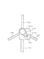
FIG. 1 is an explanatory diagram of the overall structure of the wind turbine generator of this embodiment. FIG. 2 is an explanatory diagram of the timing pulley. FIG. 3 is an explanatory diagram of a driving pulley and a belt of a generator in the wind turbine generator.
[0012]
The wind power generator of this embodiment includes a
[0013]
Further, for example, a timing pulley 114 a having a diameter of 47 mm and 29 teeth is attached to the rotating
[0014]
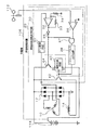
Next, details of the
[0015]
The field control device 20 includes a field start
[0016]
The F /
In the
[0017]
In the
The AND
[0018]
The
[0019]
The
The field start
[0020]
The wind power generator of this embodiment has such a configuration, and the operation thereof will be described next.
When the
[0021]
When the average wind power value for 30 seconds becomes equal to or higher than a predetermined value (2 m / s), the output voltage of the
[0022]
In this embodiment, since the
[0023]
As a result of detecting the blade shaft rotation speed in this way, when the blade shaft rotation speed becomes equal to or higher than the first value, the output voltage of the F /
[0024]
When the blade shaft rotation speed detected in accordance with the output timing of one shot pulse is lower than 170 rpm, the output of the
[0025]
On the other hand, once the blade shaft rotation speed becomes 170 rpm or more and the power generation state is entered, the low level output of the
[0026]
As described above, in the wind turbine generator according to the present embodiment, the supply of the field current is stopped until the rotational speed of the
[0027]
In addition, when detecting the rotation speed of the
[0028]
Further, by transmitting the driving force from the
[0029]
In addition, this invention is not limited to the said embodiment, A various deformation | transformation implementation is possible within the range of the summary of this invention. For example, in the above-described embodiment, power transmission is performed using the
[0030]
Further, in the above-described embodiment, when the rotational speed of the
[0031]
In the above-described embodiment, the first value, which is the rotational speed of the
[0032]
In the above-described embodiment, the rotational speed related to the power generation control is detected by the generator rotational speed based on the phase voltage frequency. However, the rotation of the
[Brief description of the drawings]
FIG. 1 is an explanatory diagram of the overall structure of a wind turbine generator according to an embodiment.
FIG. 2 is an explanatory diagram of a timing pulley.
FIG. 3 is an explanatory diagram of a driving pulley and a belt of a generator in a wind turbine generator.
FIG. 4 is a diagram showing a detailed configuration of a generator.
[Explanation of symbols]
DESCRIPTION OF
Claims (4)
前記発電機は、前記翼軸の回転数が第1の値以上であるときに界磁電流の供給を開始する制御を行う制御手段と、多相電機子巻線のいずれかの相に現れる電圧に基づいて前記翼軸の回転数を検出する回転検出手段とを備え、
前記制御手段によって一時的な前記界磁電流の供給を行ったときに、前記回転検出手段による回転数検出を行うことを特徴とする風力発電装置。A wind power generator having a generator that rotates in synchronization with the rotation of the blade axis,
The generator includes a control unit that performs control for starting supply of a field current when the rotational speed of the blade shaft is equal to or greater than a first value, and a voltage that appears in any phase of the multiphase armature winding. Rotation detecting means for detecting the rotational speed of the blade axis based on
A wind power generator characterized in that when the field current is temporarily supplied by the control means, the number of rotations is detected by the rotation detection means .
前記制御手段は、前記界磁電流を流した後に前記翼軸の回転数が、前記第1の値よりも小さな第2の値以下に低下したときに前記界磁電流の供給を停止する制御を行うことを特徴とする風力発電装置。In claim 1,
The control means performs control to stop the supply of the field current when the rotational speed of the blade shaft decreases to a second value smaller than the first value after flowing the field current. A wind power generator characterized by performing.
風力値を測定する風力計をさらに備え、
前記制御手段は、前記風力計によって測定した風力値が所定値を超えたときに、前記回転検出手段による回転数検出のための一時的な前記界磁電流の供給を行うことを特徴とする風力発電装置。 In claim 1 or 2,
It further includes an anemometer that measures the wind value,
The control means temporarily supplies the field current for detecting the number of rotations by the rotation detection means when the wind value measured by the anemometer exceeds a predetermined value. Power generation device.
前記翼軸から前記発電機の回転軸への駆動力の伝達をタイミングベルトで行う動力伝達手段をさらに備えることを特徴とする風力発電装置。 In any one of Claims 1-3,
A wind turbine generator further comprising power transmission means for transmitting a driving force from the blade shaft to the rotating shaft of the generator using a timing belt.
Priority Applications (1)
| Application Number | Priority Date | Filing Date | Title |
|---|---|---|---|
| JP2002077472A JP4134582B2 (en) | 2002-03-20 | 2002-03-20 | Wind power generator |
Applications Claiming Priority (1)
| Application Number | Priority Date | Filing Date | Title |
|---|---|---|---|
| JP2002077472A JP4134582B2 (en) | 2002-03-20 | 2002-03-20 | Wind power generator |
Publications (2)
| Publication Number | Publication Date |
|---|---|
| JP2003284393A JP2003284393A (en) | 2003-10-03 |
| JP4134582B2 true JP4134582B2 (en) | 2008-08-20 |
Family
ID=29227990
Family Applications (1)
| Application Number | Title | Priority Date | Filing Date |
|---|---|---|---|
| JP2002077472A Expired - Fee Related JP4134582B2 (en) | 2002-03-20 | 2002-03-20 | Wind power generator |
Country Status (1)
| Country | Link |
|---|---|
| JP (1) | JP4134582B2 (en) |
Families Citing this family (13)
| Publication number | Priority date | Publication date | Assignee | Title |
|---|---|---|---|---|
| CA2542437C (en) * | 2003-10-24 | 2011-09-13 | Shinko Electric Co., Ltd. | Power supply unit, generator, and wind turbine generator |
| JP2007215295A (en) * | 2006-02-08 | 2007-08-23 | Denso Corp | Wind power generator |
| BRPI0621963A2 (en) * | 2006-09-04 | 2011-12-27 | Sun Shouquan | belt drive device for accelerating acceleration in wind generator set |
| KR101168025B1 (en) | 2011-02-24 | 2012-07-27 | 삼성중공업 주식회사 | System and method for charging back-up power of wind turbine |
| JP2013100809A (en) * | 2012-06-06 | 2013-05-23 | Yoshikatsu Kagami | Wind generator with centrifugal blade |
| KR101334357B1 (en) * | 2012-06-15 | 2013-11-29 | 삼성중공업 주식회사 | Wind power generator |
| WO2015019384A1 (en) * | 2013-08-07 | 2015-02-12 | 株式会社辰巳菱機 | Wind power generator |
| JP6577078B2 (en) * | 2018-03-16 | 2019-09-18 | 三菱電機エンジニアリング株式会社 | Wind power generator and control method of wind power generator |
| JP6875323B2 (en) * | 2018-05-10 | 2021-05-19 | 三菱電機エンジニアリング株式会社 | Electromagnet power generator |
| JP7116697B2 (en) * | 2019-03-13 | 2022-08-10 | 三菱電機エンジニアリング株式会社 | generator |
| US11965481B2 (en) * | 2019-11-26 | 2024-04-23 | Cafe24 Corp. | Wind power system |
| JP7229196B2 (en) * | 2020-04-16 | 2023-02-27 | 三菱電機株式会社 | wind turbine |
| JP7197639B2 (en) * | 2021-07-09 | 2022-12-27 | 義廣 里村 | transmission mechanism, power generation system |
-
2002
- 2002-03-20 JP JP2002077472A patent/JP4134582B2/en not_active Expired - Fee Related
Also Published As
| Publication number | Publication date |
|---|---|
| JP2003284393A (en) | 2003-10-03 |
Similar Documents
| Publication | Publication Date | Title |
|---|---|---|
| JP4134582B2 (en) | Wind power generator | |
| KR101158193B1 (en) | Wind-driven generator and yaw rotation control method for wind-driven generator | |
| TWI246561B (en) | Fluid power generator system | |
| DK201070286A (en) | Method and apparatus for controlling the tip speed of a blade of a wind turbine | |
| EP1748549A3 (en) | Wind turbine generator system | |
| AU2005222229B2 (en) | Generator | |
| CN102312777A (en) | Wind turbine and method for operating a wind turbine | |
| EP2119910B1 (en) | Method of reducing torsional oscillations in the power train of a wind turbine | |
| CN203385499U (en) | Friction torque detector for bearing | |
| CA2681784A1 (en) | A speed control for wind turbines | |
| CN108225696A (en) | Energy shafting torsional oscillation tests system | |
| CN107327375B (en) | Method and device for determining fan blade parameters | |
| CN101419103A (en) | A power measurement device and power measurement method for a vertical axis wind turbine | |
| CN201852697U (en) | Backstop dynamic performance test device | |
| CN206399621U (en) | Energy shafting torsional oscillation test system | |
| JP4808049B2 (en) | Wind power generator | |
| CN2648427Y (en) | High speed motor output power testnig appliance | |
| JP2017166325A (en) | Wind power generation method in multistage vertical wind turbine | |
| CN213516336U (en) | Torque detection experiment table for permanent magnet coupler | |
| Kuznecovs et al. | Experimental determination of the characteristics of brushless DC motors using propeller as a dummy load | |
| CN208283071U (en) | Pitch-controlled system experimental rig | |
| KR101242766B1 (en) | wind-driven generator with Apparatus of reducing rotor load and method of reducing rotor load for wind-driven generator with Apparatus of reducing rotor load | |
| CN101017118A (en) | Test method for performance of high speed engine clutch | |
| CN207239219U (en) | A kind of lithium electricity Rechargeable electronic torsion adjusts electric drill | |
| RU148539U1 (en) | WIND-GYROSCOPIC POWER MODULE |
Legal Events
| Date | Code | Title | Description |
|---|---|---|---|
| A621 | Written request for application examination |
Free format text: JAPANESE INTERMEDIATE CODE: A621 Effective date: 20050216 |
|
| A977 | Report on retrieval |
Free format text: JAPANESE INTERMEDIATE CODE: A971007 Effective date: 20070807 |
|
| A131 | Notification of reasons for refusal |
Free format text: JAPANESE INTERMEDIATE CODE: A131 Effective date: 20070821 |
|
| A521 | Written amendment |
Free format text: JAPANESE INTERMEDIATE CODE: A523 Effective date: 20071010 |
|
| TRDD | Decision of grant or rejection written | ||
| A01 | Written decision to grant a patent or to grant a registration (utility model) |
Free format text: JAPANESE INTERMEDIATE CODE: A01 Effective date: 20080507 |
|
| A01 | Written decision to grant a patent or to grant a registration (utility model) |
Free format text: JAPANESE INTERMEDIATE CODE: A01 |
|
| A61 | First payment of annual fees (during grant procedure) |
Free format text: JAPANESE INTERMEDIATE CODE: A61 Effective date: 20080520 |
|
| R150 | Certificate of patent or registration of utility model |
Ref document number: 4134582 Country of ref document: JP Free format text: JAPANESE INTERMEDIATE CODE: R150 Free format text: JAPANESE INTERMEDIATE CODE: R150 |
|
| FPAY | Renewal fee payment (event date is renewal date of database) |
Free format text: PAYMENT UNTIL: 20110613 Year of fee payment: 3 |
|
| FPAY | Renewal fee payment (event date is renewal date of database) |
Free format text: PAYMENT UNTIL: 20110613 Year of fee payment: 3 |
|
| FPAY | Renewal fee payment (event date is renewal date of database) |
Free format text: PAYMENT UNTIL: 20120613 Year of fee payment: 4 |
|
| FPAY | Renewal fee payment (event date is renewal date of database) |
Free format text: PAYMENT UNTIL: 20120613 Year of fee payment: 4 |
|
| FPAY | Renewal fee payment (event date is renewal date of database) |
Free format text: PAYMENT UNTIL: 20130613 Year of fee payment: 5 |
|
| FPAY | Renewal fee payment (event date is renewal date of database) |
Free format text: PAYMENT UNTIL: 20140613 Year of fee payment: 6 |
|
| R250 | Receipt of annual fees |
Free format text: JAPANESE INTERMEDIATE CODE: R250 |
|
| R250 | Receipt of annual fees |
Free format text: JAPANESE INTERMEDIATE CODE: R250 |
|
| R250 | Receipt of annual fees |
Free format text: JAPANESE INTERMEDIATE CODE: R250 |
|
| R250 | Receipt of annual fees |
Free format text: JAPANESE INTERMEDIATE CODE: R250 |
|
| R250 | Receipt of annual fees |
Free format text: JAPANESE INTERMEDIATE CODE: R250 |
|
| LAPS | Cancellation because of no payment of annual fees |