JP4135577B2 - Temperature measuring device and air conditioner using the same - Google Patents
Temperature measuring device and air conditioner using the same Download PDFInfo
- Publication number
- JP4135577B2 JP4135577B2 JP2003183832A JP2003183832A JP4135577B2 JP 4135577 B2 JP4135577 B2 JP 4135577B2 JP 2003183832 A JP2003183832 A JP 2003183832A JP 2003183832 A JP2003183832 A JP 2003183832A JP 4135577 B2 JP4135577 B2 JP 4135577B2
- Authority
- JP
- Japan
- Prior art keywords
- temperature
- measuring device
- sensor unit
- sensor
- cover body
- Prior art date
- Legal status (The legal status is an assumption and is not a legal conclusion. Google has not performed a legal analysis and makes no representation as to the accuracy of the status listed.)
- Expired - Fee Related
Links
Images



Landscapes
- Air Conditioning Control Device (AREA)
- Radiation Pyrometers (AREA)
Description
【0001】
【発明の属する技術分野】
本発明は、赤外線を検知する検知手段を用いて放射温度分布を測定する温度測定装置及びそれを用いた空気調和装置に関する。
【0002】
【従来の技術】
従来より、この種の温度測定装置として、室内空間に設置された検知手段のセンサ部を回動して、赤外線の光量信号と回動時の位置信号とから室内空間の温度分布を測定するものがある。その温度分布に応じて空気調和装置が制御され、室内の温度分布が均一に保持される。
【0003】
このような温度測定装置のセンサ部は、赤外線センサと、該赤外線センサの前に設けられて赤外線を赤外線センサに集光するフレネルレンズとを有している。
【0004】
この温度測定装置において、室内空気がフレネルレンズに直接に接するので、フレネルレンズの透過率等の要因から、該フレネルレンズと赤外線センサとの間に温度差が生じる。この結果、赤外線センサが人などの赤外線をそのまま検知しないという問題があった。特に、空気調和装置の起動時のように、室内の温度が大きく変動するときには、室内の空気に直接面するセンサ部のフレネルレンズ自体の温度と赤外線センサ自体の温度とに差が生じることが多い。赤外線センサはフレネルレンズから放射される赤外線も感知するため、この温度差のある状態では、赤外線センサによって得られた出力信号による測定温度は、実際の室内の温度とは異なる誤差を含んだものとなる。
【0005】
そこで、従来、例えば特許文献1に示される温度測定装置のように、フレネルレンズの裏面に温度センサを設け、この温度センサによってフレネルレンズ自体の温度を直接測定し、赤外線センサから得られる出力信号による測定温度を補正するものが知られている。
【0006】
しかし、このようなフレネルレンズ自体の温度を直接測定するものでは、フレネルレンズの温度を測定するために、新たに温度センサが必要となる上、熱容量の小さいフレネルレンズの温度を正確に測定することは困難である。
【0007】
一方、ドーム状の保護カバーを設けてフレネルレンズを含むセンサ部を室内の雰囲気から遮断し、センサ部が室内の温度変化や埃等による汚れの影響を受けないようにするものが提案されている(例えば、特許文献2参照)。
【0008】
また、例えば、特許文献3では、赤外線センサの走査範囲内の温度測定装置と離れた位置に温度基準体を配置し、この温度基準体に設けられた温度センサにより、温度基準体の表面温度を検出して温度測定装置の赤外線センサから得られる出力信号による測定温度を補正するものが知られている。
【0009】
【特許文献1】
特開平2−196933号公報
【0010】
【特許文献2】
特開平6−147999号公報
【0011】
【特許文献3】
特公平5−70055号公報
【0012】
【発明が解決しようとする課題】
上記従来のセンサ部を覆う保護カバーを設けるものでは、センサ部全体は均一な温度に維持されるものの、保護カバーとセンサ部との間で新たに温度差が生じる。この結果、センサ部の測定温度に誤差が生じるという問題があった。
【0013】
また、上記温度基準体の表面温度を検出するものでは、温度基準体を別途設けなければならず、構造が複雑となり、コストがかかるという問題がある。
【0014】
さらに、保護カバーの温度は、保護カバー外部の雰囲気温度及び保護カバーの接する取付機器の表面温度の影響を受けるため、温度基準体等による室内温度測定のみでは不十分で、保護カバー自体の温度を正確に測定する必要がある。一方、保護カバー自体の温度を測定する方法としては、サーミスタ等の使用も考えられるが、赤外線透過率を高める目的から、保護カバーは非常に薄く、その熱容量は小さいため、正確に保護カバーの温度を測定することは難しい。
【0015】
本発明は斯かる諸点に鑑みてなされたものであり、その目的とするところは、センサ部を覆う保護カバーの温度を測定する構成に工夫を加えることにより、新規の温度センサ等を追加することなく、誤差の少ない温度測定が行える温度測定装置及びそれを備えた空気調和装置を提供することにある。
【0016】
【課題を解決するための手段】
上記の目的を達成するために、請求項1の発明では、対象空間の赤外線を検知する検知手段(20)を備え、対象空間の温度を測定する温度測定装置を対象とする。
【0017】
そして、上記検知手段(20)は、赤外線を感知する回動自在なセンサ部(30)と、このセンサ部(30)を覆うカバー体(40)とを備え、このカバー体(40)には、センサ部(30)が対象空間の赤外線を感知するための測定領域(42)と、センサ部(30)がカバー体(40)の赤外線を感知するように測定領域(42)の赤外線透過率よりも赤外線透過率が低い低透過領域(41)とが形成される一方、センサ部(30)がカバー体(40)の測定領域(42)を介して感知した赤外線の出力信号からセンサ部( 30 )が感知したカバー体( 40 )の低透過領域( 41 )の赤外線の出力信号を減算補正する補正手段(51)を備えている。
【0018】
上記の構成によると、検知手段(20)のセンサ部(30)は、回動されて対象空間の赤外線を感知する。センサ部(30)を保護するカバー体(40)の低透過領域(41)は赤外線を通し難い。センサ部(30)はこのカバー体(40)の低透過領域(41)を介してカバー体(40)の赤外線を感知する。一方、カバー体(40)の測定領域(42)は低透過領域(41)に比べて赤外線を通し易い。センサ部(30)はこのカバー体(40)の測定領域(42)を介して対象空間の赤外線を感知する。センサ部(30)がカバー体(40)の測定領域(42)を介して感知した赤外線の出力信号は、センサ部(30)が感知したカバー体(40)の低透過領域(41)の赤外線の出力信号に基づいて補正手段(51)によって減算補正される。このことで、温度測定装置は対象空間の温度を測定する。
【0019】
請求項2の発明では、検知手段(20)は、センサ部(30)を回動させる走査機構(22)を備え、センサ部(30)と走査機構(22)とカバー体(40)とが一体に形成されるものとする。
【0020】
上記の構成によると、センサ部(30)は走査機構(22)によって回動される。検知手段(20)のセンサ部(30)と走査機構(22)とカバー体(40)とが1つのユニットとして取り付けられ又は取り外される。
【0021】
請求項3の発明では、走査機構(22)は、互いに直交する2つの軸を中心にセンサ部(30)を回動させるように構成され、カバー体(40)は、センサ部(30)の2つの回動軸の少なくともいずれか1つの回動軸を中心に回動するように構成されている。
【0022】
上記の構成によると、センサ部(30)は、走査機構(22)によって互いに直交する2つの軸を中心に回動される。このセンサ部(30)の2つの回動軸の少なくともいずれか1つの回動軸を中心にカバー体(40)が回動する。
【0023】
請求項4の発明では、上記請求項1から3のいずれか1項の温度測定装置を備えている。この構成では、対象空間に設置された検知手段(20)のセンサ部(30)が対象空間を走査し、赤外線の出力信号から対象空間の温度分布を測定し、その温度分布に応じて空気調和装置が制御される。
【0024】
請求項5の発明では、天井埋込形又は天井吊下型の室内機(10)を備え、温度測定装置は、室内機(10)の前面パネル(12)の開口(15)から温度を測定するように構成されている一方、温度測定装置におけるカバー体(40)の低透過領域(41)は、前面パネル(12)から真下に向かう部分に形成されるものとする。
【0025】
上記の構成によると、温度測定装置は、天井埋込形又は天井吊下型の室内機(10)の前面パネル(12)に設けられ、天井側から下側に向けられる状態で赤外線を感知して温度を測定する。室内機(10)の空調が直接届かない対象空間に対応するカバー体(40)の下側部分にカバー体(40)の低透過領域(41)が形成されている。
【0026】
【発明の実施の形態】
以下、本発明の実施形態を図面に基づいて説明する。なお、以下の実施形態は、本質的に好ましい例示に過ぎず、本発明、その適用物や用途の範囲を制限することを意図するものでは全くない。
【0027】
図1に本願発明の実施形態に係るセパレート型の空気調和装置の室内機(10)を示す。この室内機(10)は、室内の天井に埋設配置される天井埋込型の室内機(10)である。室内機(10)は、天井の上側に埋設配置される矩形箱状のケーシング(11)と該ケーシング(11)の下端開口側に室内側から装着される矩形平板状の前面パネル(12)とを備えている。なお、以下では、上下というと室内機(10)の設置状態における上下方向を表すものとする。
【0028】
前面パネル(12)には、その中央部に矩形開口状の吸込口(13)が設けられると共に、この吸込口(13)を囲むように4つの吹出口(14)が該前面パネル(12)の周縁に設けられる。
【0029】
詳細は図示しないが、上記ケーシング(11)内には、吸込口(13)の上方に遠心式のファンが配置され、ファンの外周側に熱交換器が配置される。
【0030】
さらに、上記前面パネル(12)の室内に露出する表面側の1つの角部には温度測定装置の検知手段としてのセンサユニット(20)が配置される。このセンサユニット(20)は、室内機(10)を天井側に設置した状態において、室内の壁面、床面又は人体等の検知対象物からの赤外線を検知し、これを現在の室内温度に関する検知情報として出力する。
【0031】
図2に拡大詳示するように、センサユニット(20)は、上記前面パネル(12)の外周側の4つの角部のうちの1つに開口するセンサ取付孔(15)に挿入された状態で配置されている。センサユニット(20)は、その筒状の取付ブラケット(21)を前面パネル(12)に固定した状態でセンサ取付孔(15)に取付固定されている。
【0032】
上記取付ブラケット(21)には、赤外線を検出するための赤外線センサ(32)を所望の方向に向けるための走査機構(22)が設けられている。走査機構(22)は水平方向回動と垂直方向回動の2軸の回動機構を有する。
【0033】
具体的には、上記取付ブラケット(21)の上側には、該取付ブラケット(21)を垂直方向に貫通する垂直シャフト(23a)を有する水平回動モータ(23)が設けられている。この水平回動モータ(23)の垂直シャフト(23a)の先端側には、水平回動部(24)が回動可能に支持されている。
【0034】
上記水平回動部(24)には、上記垂直シャフト(23a)に対して90°の角度を有する水平シャフト(図示せず)を駆動軸とする垂直回動モータ(25)が配置されている。水平回動部(24)の水平モータと反対側の下端部には、赤外線センサ(32)を含むセンサ部(30)が配置されている。垂直回動モータ(25)の水平シャフトの端部は、このセンサ部(30)の側方からセンサ部(30)に挿入されている。このことで、センサ部(30)が略180°の範囲に亘り往復揺動される。
【0035】
上記センサ部(30)が、走査機構(22)における水平回動モータ(23)により、その垂直シャフト(23a)を中心に水平面内で360°回動される。また、垂直回動モータ(25)により、その水平シャフトを中心に略180°の範囲を往復揺動されることで、このセンサ部(30)は室内の広範囲に亘って走査可能とされている。
【0036】
図3に拡大詳示するように、センサ部(30)は、筒状のレンズホルダ(31)と、このレンズホルダ(31)の一端に配設された赤外線センサ(32)と、該赤外線センサ(32)と所定の距離を置いた他端に設けられたフレネルレンズ(33)とを有する。
【0037】
上記フレネルレンズ(33)は、例えばポリエチレン等の樹脂材料からなり、赤外線透過量が高いものとなっている。このフレネルレンズ(33)により、赤外線の方向が限定され、赤外線センサ(32)に指向性が与えられると共に、赤外線が効率よく赤外線センサ(32)に入力される。
【0038】
上記赤外線センサ(32)は、人体及び壁面等から放射される赤外線を上記フレネルレンズ(33)を通して検知するものである。赤外線センサ(32)には、例えばサーモパイルが使用されている。つまり、赤外線センサ(32)は、熱電対を直列につないで高電圧の出力を得るようになっている。又は、赤外線センサ(32)は熱電対を並列にして大電流の出力を得るようにしたものでもよい。
【0039】
上記フレネルレンズ(33)及び赤外線センサ(32)は光学部品であり、埃等の汚れの影響を受けやすい。また、フレネルレンズ(33)又は赤外線センサ(32)に室内空気の風等が直接当たると室内の正確な温度が測れない。このため、図2に示すように、センサ部(30)は、カバー体としてのドーム状の保護カバー(40)によってその下側部分を覆われ、室内の雰囲気から遮断されている。
【0040】
室内空気の温度を測定するためには、上記赤外線センサ(32)に波長が5μm以上の赤外線量を入射する必要があり、上記保護カバー(40)には、この波長領域で透過率の高いポリエチレンを使用する。保護カバー(40)は、例えば厚さ0.5mmの非常に薄い板厚のものからなる。
【0041】
上記保護カバー(40)は、取付ブラケット(21)に取付固定されており、センサユニット(20)は、センサ部(30)と走査機構(22)と保護カバー(40)とが一体に形成されて構成されている。
【0042】
図4に示すように、保護カバー(40)の下側の円盤状の領域は、低透過領域(41)を構成している。その低透過領域(41)の外側のその他の球面の領域が測定領域(42)を構成している。
【0043】
上記低透過領域(41)は、上記保護カバー(40)の内面に赤外線透過率の低い樹脂塗料を塗布することで形成され、その熱放射率が0.9以上となっている。この低透過領域( 41 )をセンサ部(30)が走査することで、カバー体(40)の赤外線が感知される。なお、塗布面は、測定温度精度や耐久性を考慮すると内面側が好ましい。
【0044】
上記低透過領域(41)は、前面パネルの真下側に向かう部分に位置し、低透過領域(41)の走査範囲は、室内機(10)の4つの吹出口(14)のいずれから吹き出た空気も到達することのない室内機(10)の真下側に相当する領域となっている。
【0045】
一方、図4(A)の範囲Sで示すように、測定領域(42)を通して赤外線センサ(32)は室内の赤外線を走査し、室内の温度分布を測定するようになっている。この領域は、透過率の高いポリエチレンのみからなるため、赤外線を通しやすく、保護カバー(40)自体の発する赤外線は比較的小さいものとなっている。
【0046】
図3に示すように、上記室内機(10)には、赤外線センサ(32)の検知信号を受けて風向等を制御するコントローラ(50)が設けられている。そして、このコントローラ(50)には、補正手段(51)が設けられている。該補正手段(51)は、上記センサ部(30)が感知した保護カバー(40)の低透過領域(41)の赤外線の出力信号に基づき、センサ部(30)がカバー体(40)の測定領域(42)を介して感知した赤外線の出力信号による測定温度を補正するように構成されている。
【0047】
−運転動作−
まず、センサユニット(20)において、走査機構(22)の水平回動モータ(23)及び垂直回動モータ(25)を回動させることで、センサ部(30)を保護カバー(40)における測定領域(42)を介して室内の広範囲に亘って連続的に走査させる(図4(A)の範囲S)。
【0048】
一連の走査の後、センサ部(30)が保護カバー(40)における低透過領域(41)を走査する。
【0049】
このようにして、センサ部(30)が保護カバー(40)における測定領域(42)を介して感知した赤外線の出力信号と位置信号とがコントローラ(50)に出力される。そして、センサ部(30)が保護カバー(40)における低透過領域(41)を介して感知した赤外線の出力信号と位置信号とがコントローラ(50)に出力される。
【0050】
このとき、垂直回動モータ(25)の通電時間をできるだけ短くし、保護カバー(40)内への熱の流入をできるだけ小さくするような構造とすることで、センサユニット(20)自体が発する熱の影響が低減できる。そのような状態では、センサ部(30)自体の温度は、ほぼ均一になり、温度測定誤差の熱的要因は保護カバー(40)とセンサ部(30)の温度差のみとみなせる。
【0051】
上記出力信号を受けたコントローラ(50)は、制御手段(51)において、センサ部(30)が測定領域(42)を介して感知した赤外線の出力信号から、センサ部(30)が感知した低透過領域(41)の赤外線の出力信号を減算補正する。
【0052】
上記補正を数分に一度行いながら、温度測定装置が室内の温度測定を行う。
【0053】
このような温度測定装置による室内の温度測定結果から、例えば室内の人のいる位置に合わせて、壁面や床面からの放射熱がその人に不快感を与えないように、理想的な風量、風向及び空気の吹出温度を算出し、その算出結果に基づいて空気調和装置が制御される。
【0054】
−実施形態の効果−
本実施形態に係る温度測定装置は、センサ部(30)が感知した保護カバー(40)の低透過領域(41)の赤外線の出力信号に基づき、センサ部(30)が保護カバー(40)の測定領域(42)を介して感知した赤外線の出力信号による測定温度を補正する補正手段(51)を備えている。このため、センサ部(30)が、赤外線を通しにくい保護カバー(40)の低透過領域(41)を走査して、この低透過領域(41)を介して得られた赤外線により、保護カバー(40)自身の温度を直接保護カバー(40)から測定することができる。したがって、保護カバー(40)の接する空気調和装置の前面パネル(12)の表面温度の影響を受けずに、センサユニット(20)によって保護カバー(40)の温度を正確に測定することができる。この保護カバー(40)の温度が判れば、保護カバー(40)の測定領域(42)を介して感知された赤外線の出力データから保護カバー(40)の温度の影響を補正して対象空間の温度を正確に測定することができる。よって、保護カバー(40)の温度を測定するために別途温度センサを設ける必要もなく、正確に対象空間の温度を測定できる安価な温度測定装置が得られる。
【0055】
本実施形態に係る温度測定装置は、センサ部(30)と走査機構(22)と保護カバー(40)とが一体に形成されている。センサユニット(20)においては、製品ごとに保護カバー(40)自身のそれぞれの光学特性の影響を受けないように、センサ部(30)との調整が必要となるが、本実施形態に係る温度測定装置では、センサ部(30)と走査機構(22)と保護カバー(40)とを1つのユニットとして空気調和装置の前面パネル(12)に取り付け又は取り外しできるので、前面パネル(12)に取り付ける前にその調整が可能である。したがって、センサユニット(20)の取付後に調整を行う必要がないので、センサユニット(20)の取付作業が非常に容易となる。
【0056】
本実施形態に係る空気調和装置では、温度測定装置によって室内空間の温度分布を正確に測定することができるので、その温度分布に応じて空気調和装置を制御することにより、きめ細やかな空調制御が可能となる。
【0057】
本実施形態に係る空気調和装置では、温度測定装置を天井埋込形又は天井吊下型の室内機(10)の前面パネル(12)の開口(15)から温度を測定するように構成し、保護カバー(40)の低透過領域(41)を前面パネル(12)から真下に向かう部分に形成している。このため、低透過領域(41)は測定領域(42)と同様に対象空間と接しているため、測定結果に影響を与える測定領域(42)の保護カバー(40)自身の温度と同等の温度を正確に測定することができる。一方、保護カバー(40)の前面パネル(12)から真下に向かう部分は、空気調和装置の空調が直接届かない対象空間の走査範囲に相当するので、低透過領域(41)が測定領域(42)と重なることはなく、保護カバー(40)の領域を有効に使用することができる。
【0058】
本実施形態に係る空気調和装置では、保護カバー(40)の低透過領域(41)を赤外線透過率が低い樹脂塗料を塗布して形成している。このため、赤外線透過率が低い樹脂塗料を保護カバー(40)に塗布するだけで保護カバー(40)に容易に低透過領域(41)を形成することができる。したがって、安価な温度測定装置が得られる。
【0059】
−実施形態の変形例−
本実施形態の変形例では、保護カバー(40)を、センサ部(30)における走査機構(22)の2つのシャフトの少なくともいずれか1つの回動軸を中心に回動するように構成してもよい。例えば、保護カバー(40)を上記水平回動部(24)に固定することで、保護カバー(40)を水平回動モータ(23)の垂直シャフト(23a)を中心に回動させることができる。
【0060】
このようにすることで、本変形例に係る温度測定装置では、保護カバー(40)の特定の領域に汚れが蓄積されず、汚れによる影響が少なくなる。また、赤外線透過率を高める目的から、通常保護カバー(40)は非常に薄く成形されているため、風当たり等により保護カバー(40)の特定方向のみ温度分布が不均一になりやすいが、本変形例に係る温度測定装置では、保護カバー(40)が回転されることで保護カバー(40)の温度分布が均一化される。また、保護カバー(40)が水平回動モータ(23)の垂直シャフト(23a)と同期しているので、センサ部(30)の保護カバー(40)における走査範囲が限定され、保護カバー(40)における不均一な汚れの付着の影響を低減できる。したがって、特定の測定位置に測定誤差を蓄積させるのを防ぐことができる。
【0061】
さらに、保護カバー(40)が回動することで、監視カメラのように見えるので、防犯効果も期待できる。
【0062】
また、本実施形態の別の変形例では、保護カバー(40)において、低透過領域(41)のみを赤外線透過率の低い(熱放射率が0.9以上の)樹脂で成形すると共に、測定領域(42)をポリエチレンで成形する2色成形によって保護カバー(40)を成形してもよい。
【0063】
上記実施形態では、空気調和装置の室内機(10)は、室内の天井に埋設配置される天井埋込型の室内機(10)としたが、本実施形態のもう一つの変形例では、天井吊下型の室内機(10)としてもよい。また、空気調和装置の室内機(10)を壁掛けタイプにしてもよい。このときには、保護カバー(40)も室内機(10)の前面パネル(12)に沿って半球面の中心軸が室内側に向くように置かれ、例えば、その下側の球面の1/4に相当する部分を測定領域とする一方、上側球面の空調の届かない走査範囲に相当する部分に低透過領域を設ければよい。
【0064】
【発明の効果】
以上説明したように、請求項1の発明の温度測定装置は、検知手段(20)のセンサ部(30)が感知したカバー体(40)の低透過領域(41)の赤外線の出力信号に基づき、センサ部(30)がカバー体(40)の測定領域(42)を介して感知した赤外線の出力信号による測定温度を補正する補正手段(51)を備えている。このため、センサ部(30)は、赤外線を通しにくいカバー体(40)の低透過領域(41)を走査して、この低透過領域(41)を介して得られた赤外線により、カバー体(40)自身の温度を直接カバー体(40)から測定することができる。したがって、カバー体(40)の接する取付機器の表面温度の影響を受けずに、検知手段(20)によってカバー体(40)の温度を正確に測定することができる。このカバー体(40)の温度が判れば、カバー体(40)の測定領域(42)を介して感知された赤外線の出力データからカバー体(40)の温度の影響を補正して対象空間の温度を正確に測定することができる。よって、カバー体(40)の温度を測定するために別途温度センサを設ける必要もなく、正確に対象空間の温度を測定できる安価な温度測定装置が得られる。
【0065】
請求項2の発明は、センサ部(30)と走査機構(22)とカバー体(40)とが一体に形成されている。検知手段(20)においては、製品ごとにカバー体(40)自身のそれぞれの光学特性の影響を受けないように、センサ部(30)との調整が必要となるが、この発明の温度測定装置では、センサ部(30)と走査機構(22)とカバー体(40)とを1つのユニットとして空気調和装置等の機器に取り付け又は取り外しできるので、機器に取り付ける前にその調整が可能である。したがって、検出手段(20)の取付後に調整を行う必要がないので、検知手段(20)の取付作業が非常に容易となる。
【0066】
請求項3の発明では、カバー体(40)をセンサ部(30)の2つの回動軸の少なくともいずれか1つの回動軸を中心に回動させる。このため、カバー体(40)の特定の領域に汚れが蓄積されず、汚れによる影響が少なくなる。また、赤外線透過率を高める目的から、通常カバー体(40)は非常に薄く成形されているため、風当たり等によりカバー体(40)の特定方向のみ温度分布が不均一になりやすいが、この発明の温度測定装置では、カバー体(40)が回転されることでカバー体(40)の温度分布が均一化される。したがって、特定の測定位置に測定誤差を蓄積させるのを防ぐことができる。
【0067】
請求項4の発明では、請求項1から3のいずれか1項の温度測定装置を備えている。このため、本発明の温度測定装置によって室内空間の温度分布を正確に測定することができるので、その温度分布に応じて空気調和装置を制御することにより、きめ細やかな空調制御が可能となる。
【0068】
請求項5の発明では、温度測定装置は、天井埋込形又は天井吊下型の室内機(10)の前面パネル(12)の開口(15)から温度を測定するように構成し、カバー体(40)の低透過領域(41)を前面パネル(12)から真下に向かう部分に形成している。このため、低透過領域(41)は測定領域(42)と同様に対象空間と接しているため、測定結果に影響を与える測定領域(42)のカバー体(40)自身の温度と同等の温度を正確に測定することができる。一方、カバー体(40)の前面パネル(12)から真下に向かう部分は、空気調和装置の空調が直接届かない対象空間の走査範囲に相当するので、低透過領域(41)が測定領域(42)と重なることはなく、カバー体(40)の領域を有効に使用することができる。
【図面の簡単な説明】
【図1】 本発明の実施形態に係る温度測定装置を備えた室内機を室内側から見た斜視図である。
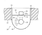
【図2】 温度測定装置のセンサ部を側方から見た断面図である。
【図3】 温度測定装置を側方から見た断面図である。
【図4】 本発明の実施形態に係る温度測定装置における保護カバーを示し、(A)は保護カバーを側方から見た断面図で、(B)は保護カバーの平面図である。
【符号の説明】
10 室内機
12 前面パネル
20 検知手段(センサユニット)
22 走査機構
30 センサ部
40 カバー体(保護カバー)
41 低透過領域
42 測定領域
51 補正手段[0001]
BACKGROUND OF THE INVENTION
The present invention relates to a temperature measuring device that measures a radiation temperature distribution using a detecting means that detects infrared rays, and an air conditioner using the same.
[0002]
[Prior art]
Conventionally, as this type of temperature measurement device, the temperature of the indoor space is measured from the light quantity signal of infrared light and the position signal at the time of rotation by rotating the sensor part of the detecting means installed in the indoor space. There is. The air conditioner is controlled according to the temperature distribution, and the temperature distribution in the room is kept uniform.
[0003]
The sensor unit of such a temperature measuring device has an infrared sensor and a Fresnel lens that is provided in front of the infrared sensor and collects infrared rays on the infrared sensor.
[0004]
In this temperature measuring device, since the indoor air is in direct contact with the Fresnel lens, a temperature difference occurs between the Fresnel lens and the infrared sensor due to factors such as the transmittance of the Fresnel lens. As a result, there has been a problem that the infrared sensor does not detect infrared rays from people or the like. In particular, when the indoor temperature fluctuates greatly, such as when the air conditioner is started, there is often a difference between the temperature of the Fresnel lens itself of the sensor unit directly facing the indoor air and the temperature of the infrared sensor itself. . Since the infrared sensor also senses the infrared radiation emitted from the Fresnel lens, the temperature measured by the output signal obtained by the infrared sensor in this state with a temperature difference includes an error that differs from the actual indoor temperature. Become.
[0005]
Therefore, conventionally, a temperature sensor is provided on the back surface of the Fresnel lens, for example, as in the temperature measuring device shown in Patent Document 1, and the temperature of the Fresnel lens itself is directly measured by this temperature sensor, and the output signal obtained from the infrared sensor is used. One that corrects the measured temperature is known.
[0006]
However, in the case of directly measuring the temperature of the Fresnel lens itself, a new temperature sensor is required to measure the temperature of the Fresnel lens, and the temperature of the Fresnel lens having a small heat capacity must be accurately measured. It is difficult.
[0007]
On the other hand, a dome-shaped protective cover is provided to shield the sensor unit including the Fresnel lens from the indoor atmosphere so that the sensor unit is not affected by indoor temperature changes or dirt due to dust or the like. (For example, refer to Patent Document 2).
[0008]
Further, for example, in Patent Document 3, a temperature reference body is disposed at a position away from the temperature measuring device within the scanning range of the infrared sensor, and the surface temperature of the temperature reference body is determined by the temperature sensor provided on the temperature reference body. What detects and correct | amends the measurement temperature by the output signal obtained from the infrared sensor of a temperature measuring device is known.
[0009]
[Patent Document 1]
Japanese Patent Laid-Open No. 2-196933
[0010]
[Patent Document 2]
JP-A-6-147999
[0011]
[Patent Document 3]
Japanese Patent Publication No. 5-70055
[0012]
[Problems to be solved by the invention]
In the case where a protective cover that covers the conventional sensor unit is provided, the entire sensor unit is maintained at a uniform temperature, but a new temperature difference occurs between the protective cover and the sensor unit. As a result, there is a problem that an error occurs in the measured temperature of the sensor unit.
[0013]
In addition, in the case of detecting the surface temperature of the temperature reference body, a temperature reference body must be provided separately, and there is a problem that the structure is complicated and the cost is high.
[0014]
Furthermore, since the temperature of the protective cover is affected by the ambient temperature outside the protective cover and the surface temperature of the mounting equipment that is in contact with the protective cover, it is not sufficient to measure the indoor temperature with a temperature reference body. It is necessary to measure accurately. On the other hand, a thermistor can be used as a method for measuring the temperature of the protective cover itself, but for the purpose of increasing the infrared transmittance, the protective cover is very thin and its heat capacity is small, so the temperature of the protective cover is accurate. It is difficult to measure.
[0015]
The present invention has been made in view of these points, and the object of the present invention is to add a new temperature sensor or the like by devising a configuration for measuring the temperature of the protective cover covering the sensor unit. It is another object of the present invention to provide a temperature measuring device that can perform temperature measurement with little error and an air conditioner including the same.
[0016]
[Means for Solving the Problems]
In order to achieve the above object, the invention of claim 1 is directed to a temperature measuring device that includes a detecting means (20) for detecting infrared rays in a target space and measures the temperature of the target space.
[0017]
The detection means (20) includes a rotatable sensor part (30) for sensing infrared rays and a cover body (40) covering the sensor part (30). The cover body (40) The measurement region (42) for the sensor unit (30) to detect infrared rays in the target space, and the measurement region (42) for the sensor unit (30) to detect infrared rays from the cover body (40).Infrared transmittanceA low transmission region (41) having a lower infrared transmittance thanWayInfrared output signal detected by sensor part (30) through measurement area (42) of cover body (40)To sensor part ( 30 ) Detected by the cover ( 40 ) Low transmission area ( 41 ) Subtract infrared output signalCorrection means (51) for correcting is provided.
[0018]
According to said structure, the sensor part (30) of a detection means (20) is rotated and senses the infrared rays of object space. The low transmission region (41) of the cover body (40) protecting the sensor unit (30) is difficult to transmit infrared rays. The sensor unit (30) senses infrared rays of the cover body (40) via the low transmission region (41) of the cover body (40). On the other hand, the measurement region (42) of the cover body (40) is easier to transmit infrared rays than the low transmission region (41). The sensor unit (30) senses infrared rays in the target space via the measurement region (42) of the cover body (40). Infrared output signal detected by sensor unit (30) through measurement area (42) of cover body (40)IssueBased on the infrared output signal of the low transmission region (41) of the cover body (40) sensed by the sensor unit (30), the correction means (51)SubtractionIt is corrected. Thus, the temperature measuring device measures the temperature of the target space.
[0019]
In the invention of claim 2, the detection means (20) includes a scanning mechanism (22) for rotating the sensor portion (30), and the sensor portion (30), the scanning mechanism (22), and the cover body (40) are provided. It shall be formed integrally.
[0020]
According to said structure, a sensor part (30) is rotated by a scanning mechanism (22). The sensor unit (30), the scanning mechanism (22), and the cover body (40) of the detection means (20) are attached or removed as one unit.
[0021]
In the invention of claim 3, the scanning mechanism (22) is configured to rotate the sensor unit (30) about two axes orthogonal to each other, and the cover body (40) It is comprised so that it may rotate centering on at least any one of two rotation axes.
[0022]
According to said structure, a sensor part (30) is rotated centering | focusing on two axes | shafts orthogonal to each other by a scanning mechanism (22). The cover body (40) rotates around at least one of the two rotation shafts of the sensor unit (30).
[0023]
The invention according to claim 4 includes the temperature measuring device according to any one of claims 1 to 3. In this configuration, the sensor unit (30) of the detection means (20) installed in the target space scans the target space, measures the temperature distribution of the target space from the infrared output signal, and adjusts the air conditioning according to the temperature distribution. The device is controlled.
[0024]
According to the invention of claim 5, a ceiling-embedded or ceiling-suspended indoor unit (10) is provided, and the temperature measuring device measures the temperature from the opening (15) of the front panel (12) of the indoor unit (10). On the other hand, it is assumed that the low transmission region (41) of the cover body (40) in the temperature measuring device is formed in a portion directly below the front panel (12).
[0025]
According to the above configuration, the temperature measuring device is provided on the front panel (12) of the ceiling-embedded or ceiling-suspended indoor unit (10), and senses infrared rays in a state where it is directed downward from the ceiling side. Measure the temperature. The low transmission area (41) of the cover body (40) is formed in the lower part of the cover body (40) corresponding to the target space where the air conditioning of the indoor unit (10) cannot reach directlyThe
[0026]
DETAILED DESCRIPTION OF THE INVENTION
Hereinafter, embodiments of the present invention will be described with reference to the drawings. The following embodiments are merely preferred examples in nature, and are not intended to limit the scope of the present invention, its application, and uses.
[0027]
FIG. 1 shows an indoor unit (10) of a separate type air conditioner according to an embodiment of the present invention. The indoor unit (10) is a ceiling-embedded indoor unit (10) embedded in a ceiling of a room. The indoor unit (10) includes a rectangular box-shaped casing (11) embedded and arranged on the upper side of the ceiling, and a rectangular flat plate-shaped front panel (12) mounted from the indoor side to the lower end opening side of the casing (11). It has. In the following, “up and down” represents the up and down direction in the installed state of the indoor unit (10).
[0028]
The front panel (12) is provided with a suction port (13) having a rectangular opening at the center thereof, and four blowout ports (14) are provided so as to surround the suction port (13). It is provided in the periphery.
[0029]
Although not shown in detail, a centrifugal fan is disposed above the suction port (13) in the casing (11), and a heat exchanger is disposed on the outer peripheral side of the fan.
[0030]
Further, a sensor unit (20) as a detecting means of the temperature measuring device is disposed at one corner on the surface side exposed to the inside of the front panel (12). This sensor unit (20) detects infrared rays from a detection object such as an indoor wall surface, floor surface or human body in a state where the indoor unit (10) is installed on the ceiling side, and detects this with respect to the current indoor temperature. Output as information.
[0031]
As shown in detail in FIG. 2, the sensor unit (20) is inserted into the sensor mounting hole (15) that opens in one of the four corners on the outer peripheral side of the front panel (12). Is arranged in. The sensor unit (20) is mounted and fixed in the sensor mounting hole (15) in a state where the cylindrical mounting bracket (21) is fixed to the front panel (12).
[0032]
The mounting bracket (21) is provided with a scanning mechanism (22) for directing an infrared sensor (32) for detecting infrared rays in a desired direction. The scanning mechanism (22) has a biaxial rotation mechanism of horizontal rotation and vertical rotation.
[0033]
Specifically, a horizontal rotation motor (23) having a vertical shaft (23a) vertically passing through the mounting bracket (21) is provided above the mounting bracket (21). A horizontal rotation portion (24) is rotatably supported on the distal end side of the vertical shaft (23a) of the horizontal rotation motor (23).
[0034]
The horizontal rotation part (24) is provided with a vertical rotation motor (25) having a horizontal shaft (not shown) having an angle of 90 ° with respect to the vertical shaft (23a) as a drive shaft. . A sensor part (30) including an infrared sensor (32) is disposed at the lower end of the horizontal rotation part (24) opposite to the horizontal motor. The end of the horizontal shaft of the vertical rotation motor (25) is inserted into the sensor unit (30) from the side of the sensor unit (30). As a result, the sensor unit (30) is reciprocally swung over a range of approximately 180 °.
[0035]
The sensor unit (30) is rotated 360 ° in the horizontal plane around the vertical shaft (23a) by the horizontal rotation motor (23) in the scanning mechanism (22). Further, the sensor unit (30) can be scanned over a wide range in the room by being reciprocally swung in a range of about 180 ° around the horizontal shaft by the vertical rotation motor (25). .
[0036]
As shown in detail in FIG. 3, the sensor unit (30) includes a cylindrical lens holder (31), an infrared sensor (32) disposed at one end of the lens holder (31), and the infrared sensor. (32) and a Fresnel lens (33) provided at the other end at a predetermined distance.
[0037]
The Fresnel lens (33) is made of a resin material such as polyethylene and has a high infrared transmission amount. The Fresnel lens (33) limits the direction of infrared rays, imparts directivity to the infrared sensor (32), and efficiently inputs infrared rays to the infrared sensor (32).
[0038]
The infrared sensor (32) detects infrared rays radiated from a human body and a wall surface through the Fresnel lens (33). For the infrared sensor (32), for example, a thermopile is used. That is, the infrared sensor (32) is configured to obtain a high voltage output by connecting a thermocouple in series. Alternatively, the infrared sensor (32) may be a thermocouple coupled in parallel to obtain a large current output.
[0039]
The Fresnel lens (33) and the infrared sensor (32) are optical components and are easily affected by dirt such as dust. In addition, when indoor air or the like directly hits the Fresnel lens (33) or the infrared sensor (32), the accurate temperature in the room cannot be measured. For this reason, as shown in FIG. 2, the sensor part (30) is covered with a dome-shaped protective cover (40) as a cover body and is shielded from the indoor atmosphere.
[0040]
In order to measure the temperature of indoor air, it is necessary to make an infrared ray having a wavelength of 5 μm or more incident on the infrared sensor (32), and the protective cover (40) has a high transmittance in this wavelength region. Is used. The protective cover (40) is made of a very thin plate having a thickness of 0.5 mm, for example.
[0041]
The protective cover (40) is fixedly attached to the mounting bracket (21), and the sensor unit (20) is formed integrally with the sensor unit (30), the scanning mechanism (22), and the protective cover (40). Configured.
[0042]
As shown in FIG. 4, the disk-shaped region below the protective cover (40) constitutes a low transmission region (41). The other spherical area outside the low transmission area (41) constitutes the measurement area (42).
[0043]
The low transmission region (41) is formed by applying a resin paint having a low infrared transmittance on the inner surface of the protective cover (40), and its thermal emissivity is 0.9 or more. thisLow transmission area ( 41 )When the sensor unit (30) scans, the infrared rays of the cover body (40) are sensed. The coated surface is preferably on the inner surface side in consideration of measurement temperature accuracy and durability.
[0044]
The low transmission region (41) is located at a portion directly below the front panel, and the scanning range of the low transmission region (41) is blown out from any of the four outlets (14) of the indoor unit (10). It is an area corresponding to the lower side of the indoor unit (10) where air does not reach.
[0045]
On the other hand, as shown by a range S in FIG. 4A, the infrared sensor (32) scans indoor infrared rays through the measurement region (42) and measures the indoor temperature distribution. Since this region is made only of polyethylene having a high transmittance, it is easy to transmit infrared rays, and the infrared rays emitted from the protective cover (40) itself are relatively small.
[0046]
As shown in FIG. 3, the indoor unit (10) is provided with a controller (50) that receives the detection signal of the infrared sensor (32) and controls the wind direction and the like. The controller (50) is provided with correction means (51). The correction means (51) is configured so that the sensor unit (30) measures the cover body (40) based on the infrared output signal of the low transmission region (41) of the protective cover (40) sensed by the sensor unit (30). The temperature measured by the infrared output signal sensed through the region (42) is corrected.
[0047]
-Driving action-
First, in the sensor unit (20), the horizontal rotation motor (23) and the vertical rotation motor (25) of the scanning mechanism (22) are rotated to measure the sensor unit (30) in the protective cover (40). Scanning is continuously performed over a wide area in the room through the region (42) (range S in FIG. 4A).
[0048]
After a series of scans, the sensor unit (30) scans the low transmission region (41) in the protective cover (40).
[0049]
In this way, the infrared output signal and the position signal detected by the sensor unit (30) via the measurement region (42) in the protective cover (40) are output to the controller (50). Then, an infrared output signal and a position signal detected by the sensor unit (30) via the low transmission region (41) in the protective cover (40) are output to the controller (50).
[0050]
At this time, the heat generated by the sensor unit (20) itself is made by shortening the energization time of the vertical rotation motor (25) as much as possible and minimizing the inflow of heat into the protective cover (40). Can be reduced. In such a state, the temperature of the sensor unit (30) itself becomes substantially uniform, and the thermal factor of the temperature measurement error can be regarded as only the temperature difference between the protective cover (40) and the sensor unit (30).
[0051]
Upon receiving the output signal, the controller (50) detects the low level detected by the sensor unit (30) from the infrared output signal detected by the sensor unit (30) via the measurement region (42) in the control means (51). Subtract and correct the infrared output signal in the transmission region (41).
[0052]
While performing the above correction once every few minutes, the temperature measuring device measures the temperature in the room.
[0053]
From the result of indoor temperature measurement by such a temperature measuring device, for example, according to the position where the person is in the room, the ideal air volume, so that the radiant heat from the wall surface or floor does not give the person a discomfort, A wind direction and an air blowing temperature are calculated, and the air conditioner is controlled based on the calculation result.
[0054]
-Effect of the embodiment-
The temperature measuring device according to the present embodiment is based on the infrared output signal of the low transmission region (41) of the protective cover (40) sensed by the sensor unit (30). A correction means (51) for correcting the measurement temperature by the infrared output signal sensed through the measurement region (42) is provided. For this reason, the sensor unit (30) scans the low transmission region (41) of the protective cover (40) that is difficult to transmit infrared rays, and the infrared rays obtained through the low transmission region (41) 40) Its own temperature can be measured directly from the protective cover (40). Therefore, the temperature of the protective cover (40) can be accurately measured by the sensor unit (20) without being affected by the surface temperature of the front panel (12) of the air conditioner in contact with the protective cover (40). Once the temperature of the protective cover (40) is known, the influence of the temperature of the protective cover (40) is corrected from the infrared output data sensed through the measurement area (42) of the protective cover (40), and The temperature can be measured accurately. Therefore, it is not necessary to provide a separate temperature sensor for measuring the temperature of the protective cover (40), and an inexpensive temperature measuring device that can accurately measure the temperature of the target space is obtained.
[0055]
In the temperature measurement device according to the present embodiment, the sensor unit (30), the scanning mechanism (22), and the protective cover (40) are integrally formed. The sensor unit (20) needs to be adjusted with the sensor unit (30) so as not to be affected by the respective optical characteristics of the protective cover (40) itself for each product. In the measuring device, the sensor unit (30), the scanning mechanism (22), and the protective cover (40) can be attached to or removed from the front panel (12) of the air conditioner as a single unit. The adjustment is possible before. Therefore, there is no need to make an adjustment after mounting the sensor unit (20), so that the mounting operation of the sensor unit (20) becomes very easy.
[0056]
In the air conditioner according to this embodiment, the temperature distribution of the indoor space can be accurately measured by the temperature measuring device, and therefore, by controlling the air conditioner according to the temperature distribution, fine air conditioning control can be performed. It becomes possible.
[0057]
In the air conditioner according to the present embodiment, the temperature measuring device is configured to measure the temperature from the opening (15) of the front panel (12) of the ceiling-embedded or ceiling-suspended indoor unit (10), A low transmission region (41) of the protective cover (40) is formed in a portion directly below the front panel (12). For this reason, the low transmission area (41) is in contact with the target space in the same way as the measurement area (42), and therefore the temperature equivalent to the temperature of the protective cover (40) itself in the measurement area (42) that affects the measurement results. Can be measured accurately. On the other hand, the portion of the protective cover (40) that goes directly from the front panel (12) corresponds to the scanning range of the target space where the air conditioning of the air conditioner does not reach directly, so the low transmission region (41) is the measurement region (42 ) And the area of the protective cover (40) can be used effectively.
[0058]
In the air conditioner according to the present embodiment, the low transmission region (41) of the protective cover (40) is formed by applying a resin paint having a low infrared transmittance. For this reason, the low transmission region (41) can be easily formed in the protective cover (40) simply by applying a resin paint having a low infrared transmittance to the protective cover (40). Therefore, an inexpensive temperature measuring device can be obtained.
[0059]
-Modification of the embodiment-
In the modification of this embodiment, the protective cover (40) is configured to rotate around at least one of the two rotation shafts of the scanning mechanism (22) of the sensor unit (30). Also good. For example, by fixing the protective cover (40) to the horizontal rotating part (24), the protective cover (40) can be rotated around the vertical shaft (23a) of the horizontal rotating motor (23). .
[0060]
By doing so, in the temperature measuring device according to the present modification, dirt is not accumulated in a specific region of the protective cover (40), and the influence of the dirt is reduced. Also, for the purpose of increasing the infrared transmittance, the protective cover (40) is usually made very thin, so the temperature distribution tends to be non-uniform only in a specific direction of the protective cover (40) due to wind or other factors. In the temperature measuring device according to the example, the temperature distribution of the protective cover (40) is made uniform by rotating the protective cover (40). Moreover, since the protective cover (40) is synchronized with the vertical shaft (23a) of the horizontal rotation motor (23), the scanning range of the protective cover (40) of the sensor unit (30) is limited, and the protective cover (40 ) To reduce the influence of uneven dirt adhesion. Therefore, it is possible to prevent a measurement error from being accumulated at a specific measurement position.
[0061]
Furthermore, since the protective cover (40) turns and looks like a surveillance camera, it can be expected to have a crime prevention effect.
[0062]
Further, in another modification of the present embodiment, in the protective cover (40), only the low transmission region (41) is molded with a resin having a low infrared transmittance (thermal emissivity of 0.9 or more) and measured. The protective cover (40) may be molded by two-color molding in which the region (42) is molded from polyethylene.
[0063]
In the above embodiment, the indoor unit (10) of the air conditioner is a ceiling-embedded indoor unit (10) that is embedded in the ceiling of the room, but in another modification of the present embodiment, the ceiling is It may be a suspended indoor unit (10). The indoor unit (10) of the air conditioner may be a wall-mounted type. At this time, the protective cover (40) is also placed along the front panel (12) of the indoor unit (10) so that the central axis of the hemisphere faces the indoor side, for example, to 1/4 of the lower spherical surface. While the corresponding portion is used as the measurement region, the low transmission region may be provided in the portion corresponding to the scanning range where the air conditioning of the upper spherical surface does not reach.
[0064]
【The invention's effect】
As described above, the temperature measuring device according to the first aspect of the present invention is based on the infrared output signal of the low transmission region (41) of the cover body (40) sensed by the sensor unit (30) of the detecting means (20). The sensor unit (30) includes correction means (51) for correcting the measurement temperature based on the infrared output signal sensed through the measurement region (42) of the cover body (40). For this reason, the sensor unit (30) scans the low transmission region (41) of the cover body (40) that is difficult to transmit infrared rays, and the infrared rays obtained through the low transmission region (41) 40) Its own temperature can be measured directly from the cover body (40). Therefore, the temperature of the cover body (40) can be accurately measured by the detection means (20) without being affected by the surface temperature of the mounting device with which the cover body (40) is in contact. If the temperature of the cover body (40) is known, the influence of the temperature of the cover body (40) is corrected from the infrared output data sensed through the measurement area (42) of the cover body (40), and The temperature can be measured accurately. Therefore, there is no need to provide a separate temperature sensor for measuring the temperature of the cover body (40), and an inexpensive temperature measuring device that can accurately measure the temperature of the target space can be obtained.
[0065]
In the invention of claim 2, the sensor section (30), the scanning mechanism (22), and the cover body (40) are integrally formed. In the detection means (20), adjustment with the sensor unit (30) is necessary so that each product is not affected by the optical characteristics of the cover body (40) itself. Then, since the sensor unit (30), the scanning mechanism (22), and the cover body (40) can be attached to or removed from a device such as an air conditioner as a single unit, the adjustment can be made before the device is attached to the device. Therefore, since it is not necessary to make an adjustment after the detection means (20) is attached, the attaching operation of the detection means (20) becomes very easy.
[0066]
In the invention of claim 3, the cover body (40) is rotated around at least one of the two rotation shafts of the sensor section (30). For this reason, dirt is not accumulated in a specific area of the cover body (40), and the influence of the dirt is reduced. Further, for the purpose of increasing the infrared transmittance, the cover body (40) is usually formed very thin, so that the temperature distribution tends to be non-uniform only in a specific direction of the cover body (40) due to wind or the like. In the temperature measuring apparatus, the temperature distribution of the cover body (40) is made uniform by rotating the cover body (40). Therefore, it is possible to prevent a measurement error from being accumulated at a specific measurement position.
[0067]
The invention according to claim 4 includes the temperature measuring device according to any one of claims 1 to 3. For this reason, since the temperature distribution of the indoor space can be accurately measured by the temperature measurement device of the present invention, finely controlled air conditioning can be performed by controlling the air conditioner according to the temperature distribution.
[0068]
In the invention of claim 5, the temperature measuring device is configured to measure the temperature from the opening (15) of the front panel (12) of the ceiling-embedded or ceiling-suspended indoor unit (10), and the cover body A low transmission region (41) of (40) is formed in a portion directed directly from the front panel (12). For this reason, the low transmission region (41) is in contact with the target space in the same manner as the measurement region (42), and therefore the temperature equivalent to the temperature of the cover body (40) itself of the measurement region (42) that affects the measurement results. Can be measured accurately. On the other hand, the portion of the cover body (40) that goes directly from the front panel (12) corresponds to the scanning range of the target space where the air conditioning of the air conditioner does not reach directly, so the low transmission region (41) is the measurement region (42 ) And can effectively use the area of the cover body (40)The
[Brief description of the drawings]
FIG. 1 is a perspective view of an indoor unit provided with a temperature measuring device according to an embodiment of the present invention as viewed from the indoor side.
FIG. 2 is a cross-sectional view of the sensor unit of the temperature measuring device as viewed from the side.
FIG. 3 is a cross-sectional view of the temperature measuring device as viewed from the side.
4A and 4B show a protective cover in the temperature measuring device according to the embodiment of the present invention, in which FIG. 4A is a sectional view of the protective cover as viewed from the side, and FIG. 4B is a plan view of the protective cover.
[Explanation of symbols]
10 Indoor unit
12 Front panel
20 Detection means (sensor unit)
22 Scanning mechanism
30 Sensor section
40 Cover body (protective cover)
41 Low transmission region
42 Measurement area
51 Correction method
Claims (5)
上記検知手段(20)は、赤外線を感知する回動自在なセンサ部(30)と、該センサ部(30)を覆うカバー体(40)とを備え、
上記カバー体(40)には、センサ部(30)が対象空間の赤外線を感知するための測定領域(42)と、センサ部(30)がカバー体(40)の赤外線を感知するように測定領域(42)の赤外線透過率よりも赤外線透過率が低い低透過領域(41)とが形成される一方、
上記センサ部(30)がカバー体(40)の測定領域(42)を介して感知した赤外線の出力信号から上記センサ部( 30 )が感知したカバー体( 40 )の低透過領域( 41 )の赤外線の出力信号を減算補正する補正手段(51)を備えていることを特徴とする温度測定装置。A temperature measuring device comprising a detection means (20) for detecting infrared rays in a target space and measuring the temperature of the target space,
The detection means (20) includes a rotatable sensor part (30) for sensing infrared rays, and a cover body (40) covering the sensor part (30),
The cover body (40) has a measurement area (42) for the sensor unit (30) to sense infrared light in the target space, and the sensor part (30) is measured to sense infrared light from the cover body (40). While forming a low transmission region (41) having a lower infrared transmission than that of the region (42),
Upper Symbol sensor unit (30) is a cover member above the sensor unit from the infrared output signal sensed through the measurement area (42) (40) (30) cover sensed is (40) of low permeability regions (41) A temperature measuring device comprising correction means (51) for subtracting and correcting the infrared output signal .
上記検知手段(20)は、センサ部(30)を回動させる走査機構(22)を備え、センサ部(30)と走査機構(22)とカバー体(40)とが一体に形成されていることを特徴とする温度測定装置。In claim 1,
The detection means (20) includes a scanning mechanism (22) for rotating the sensor unit (30), and the sensor unit (30), the scanning mechanism (22), and the cover body (40) are integrally formed. A temperature measuring device characterized by that.
上記走査機構(22)は、互いに直交する2つの軸を中心にセンサ部(30)を回動させるように構成され、
上記カバー体(40)は、センサ部(30)の2つの回動軸の少なくともいずれか1つの回動軸を中心に回動するように構成されていることを特徴とする温度測定装置。In claim 1,
The scanning mechanism (22) is configured to rotate the sensor unit (30) around two axes orthogonal to each other,
The temperature measuring device, wherein the cover body (40) is configured to rotate around at least one of the two rotation shafts of the sensor section (30).
天井埋込形又は天井吊下型の室内機(10)を備え、
上記温度測定装置は、室内機(10)の前面パネル(12)の開口(15)から温度を測定するように構成される一方、
上記温度測定装置におけるカバー体(40)の低透過領域(41)は、前面パネル(12)から真下に向かう部分に形成されていることを特徴とする空気調和装置。 In claim 4,
Equipped with a ceiling-embedded or ceiling-suspended indoor unit (10)
While the temperature measuring device is configured to measure the temperature from the opening (15) of the front panel (12) of the indoor unit (10),
The cover body in the temperature measuring device (40) low permeability region (41) of the air conditioner location, characterized in that it is formed in a portion toward the right under the front panel (12).
Priority Applications (1)
| Application Number | Priority Date | Filing Date | Title |
|---|---|---|---|
| JP2003183832A JP4135577B2 (en) | 2003-06-27 | 2003-06-27 | Temperature measuring device and air conditioner using the same |
Applications Claiming Priority (1)
| Application Number | Priority Date | Filing Date | Title |
|---|---|---|---|
| JP2003183832A JP4135577B2 (en) | 2003-06-27 | 2003-06-27 | Temperature measuring device and air conditioner using the same |
Publications (2)
| Publication Number | Publication Date |
|---|---|
| JP2005017150A JP2005017150A (en) | 2005-01-20 |
| JP4135577B2 true JP4135577B2 (en) | 2008-08-20 |
Family
ID=34183769
Family Applications (1)
| Application Number | Title | Priority Date | Filing Date |
|---|---|---|---|
| JP2003183832A Expired - Fee Related JP4135577B2 (en) | 2003-06-27 | 2003-06-27 | Temperature measuring device and air conditioner using the same |
Country Status (1)
| Country | Link |
|---|---|
| JP (1) | JP4135577B2 (en) |
Cited By (1)
| Publication number | Priority date | Publication date | Assignee | Title |
|---|---|---|---|---|
| CN105651397A (en) * | 2016-01-27 | 2016-06-08 | 四川长虹电器股份有限公司 | Method for accurately recognizing human body temperature |
Families Citing this family (11)
| Publication number | Priority date | Publication date | Assignee | Title |
|---|---|---|---|---|
| JP4983216B2 (en) * | 2006-11-15 | 2012-07-25 | パナソニック株式会社 | State detection device and air conditioner using the same |
| JP4943496B2 (en) * | 2009-12-22 | 2012-05-30 | 三菱電機株式会社 | Air conditioner |
| JP6090620B2 (en) * | 2010-12-27 | 2017-03-08 | パナソニックIpマネジメント株式会社 | Range food |
| JP5677178B2 (en) * | 2011-04-20 | 2015-02-25 | 三菱電機株式会社 | Air conditioner |
| JP2013088248A (en) * | 2011-10-17 | 2013-05-13 | Panasonic Corp | Infrared sensor |
| JP6482912B2 (en) * | 2015-03-13 | 2019-03-13 | 株式会社チノー | Infrared detector, radiation thermometer and human body detector |
| JP6225339B2 (en) * | 2015-08-28 | 2017-11-08 | パナソニックIpマネジメント株式会社 | Air conditioner |
| JP2019045137A (en) * | 2018-11-15 | 2019-03-22 | 三菱電機株式会社 | Indoor equipment of air conditioner |
| JP7250604B2 (en) * | 2019-04-25 | 2023-04-03 | 三菱重工サーマルシステムズ株式会社 | drive |
| JP7337256B2 (en) | 2020-03-24 | 2023-09-01 | 三菱電機株式会社 | Temperature detection device and air conditioner indoor unit equipped with the temperature detection device |
| JP2024120528A (en) * | 2023-02-24 | 2024-09-05 | 三菱重工サーマルシステムズ株式会社 | Air conditioner and control method thereof |
-
2003
- 2003-06-27 JP JP2003183832A patent/JP4135577B2/en not_active Expired - Fee Related
Cited By (1)
| Publication number | Priority date | Publication date | Assignee | Title |
|---|---|---|---|---|
| CN105651397A (en) * | 2016-01-27 | 2016-06-08 | 四川长虹电器股份有限公司 | Method for accurately recognizing human body temperature |
Also Published As
| Publication number | Publication date |
|---|---|
| JP2005017150A (en) | 2005-01-20 |
Similar Documents
| Publication | Publication Date | Title |
|---|---|---|
| JP4135577B2 (en) | Temperature measuring device and air conditioner using the same | |
| JPH0520659B2 (en) | ||
| JPH02143047A (en) | Air conditioner | |
| JP4537903B2 (en) | Air conditioner | |
| JPH0379942A (en) | Air conditioner | |
| KR20160125286A (en) | Test device | |
| JPH05223319A (en) | Air conditioner | |
| CN110095960A (en) | Image forming apparatus | |
| JPH02183752A (en) | Infrared ray detecting device for air conditioner | |
| JP3751516B2 (en) | Air conditioner | |
| JPH0570055B2 (en) | ||
| JP7337256B2 (en) | Temperature detection device and air conditioner indoor unit equipped with the temperature detection device | |
| CN108646595B (en) | Air conditioner and control method thereof | |
| JP4943496B2 (en) | Air conditioner | |
| JPH06147999A (en) | Instrument and method for measuring temperatuee distribution | |
| JP2615599B2 (en) | Air conditioner | |
| JP2575556B2 (en) | Air conditioner | |
| US11994315B2 (en) | Air-conditioning apparatus | |
| JPH05106903A (en) | Air conditioner | |
| JPH05256704A (en) | Radiation heat temperature sensor | |
| JP3563803B2 (en) | Air conditioner and control method thereof | |
| JPH04353728A (en) | Radiant-heat temperature sensor | |
| JPH05199915A (en) | Hair drier | |
| JPH0539946A (en) | Air conditioner | |
| JPH05264091A (en) | Air conditioner |
Legal Events
| Date | Code | Title | Description |
|---|---|---|---|
| A621 | Written request for application examination |
Free format text: JAPANESE INTERMEDIATE CODE: A621 Effective date: 20060529 |
|
| A977 | Report on retrieval |
Free format text: JAPANESE INTERMEDIATE CODE: A971007 Effective date: 20070817 |
|
| A131 | Notification of reasons for refusal |
Free format text: JAPANESE INTERMEDIATE CODE: A131 Effective date: 20070904 |
|
| A521 | Request for written amendment filed |
Free format text: JAPANESE INTERMEDIATE CODE: A523 Effective date: 20071012 |
|
| A131 | Notification of reasons for refusal |
Free format text: JAPANESE INTERMEDIATE CODE: A131 Effective date: 20080108 |
|
| TRDD | Decision of grant or rejection written | ||
| A01 | Written decision to grant a patent or to grant a registration (utility model) |
Free format text: JAPANESE INTERMEDIATE CODE: A01 Effective date: 20080513 |
|
| A01 | Written decision to grant a patent or to grant a registration (utility model) |
Free format text: JAPANESE INTERMEDIATE CODE: A01 |
|
| A61 | First payment of annual fees (during grant procedure) |
Free format text: JAPANESE INTERMEDIATE CODE: A61 Effective date: 20080526 |
|
| FPAY | Renewal fee payment (event date is renewal date of database) |
Free format text: PAYMENT UNTIL: 20110613 Year of fee payment: 3 |
|
| FPAY | Renewal fee payment (event date is renewal date of database) |
Free format text: PAYMENT UNTIL: 20120613 Year of fee payment: 4 |
|
| FPAY | Renewal fee payment (event date is renewal date of database) |
Free format text: PAYMENT UNTIL: 20130613 Year of fee payment: 5 |
|
| LAPS | Cancellation because of no payment of annual fees |