JP4150034B2 - Stove burner - Google Patents
Stove burner Download PDFInfo
- Publication number
- JP4150034B2 JP4150034B2 JP2005266237A JP2005266237A JP4150034B2 JP 4150034 B2 JP4150034 B2 JP 4150034B2 JP 2005266237 A JP2005266237 A JP 2005266237A JP 2005266237 A JP2005266237 A JP 2005266237A JP 4150034 B2 JP4150034 B2 JP 4150034B2
- Authority
- JP
- Japan
- Prior art keywords
- plate member
- communication hole
- circumferential direction
- burner
- protrusion
- Prior art date
- Legal status (The legal status is an assumption and is not a legal conclusion. Google has not performed a legal analysis and makes no representation as to the accuracy of the status listed.)
- Expired - Fee Related
Links
- 235000011389 fruit/vegetable juice Nutrition 0.000 description 19
- 239000002184 metal Substances 0.000 description 3
- 238000004140 cleaning Methods 0.000 description 2
- 230000002093 peripheral effect Effects 0.000 description 2
- 238000007789 sealing Methods 0.000 description 2
- 238000012423 maintenance Methods 0.000 description 1
- 238000000465 moulding Methods 0.000 description 1
- 230000035515 penetration Effects 0.000 description 1
- 230000000630 rising effect Effects 0.000 description 1
Images


Landscapes
- Gas Burners (AREA)
Description
本発明は、ガスコンロで使用するコンロ用バーナに関し、特に、バーナボディに形成した上向きに開口するガス分布室を上方から覆うバーナキャップを備え、バーナキャップの上面に、周方向の間隔を存して放射状に複数の炎孔を配置し、各炎孔から周方向一方に向かう運動成分を持つ状態でガスを噴出させるようにしたコンロ用バーナに関する。 The present invention relates to a burner for a stove that is used in a gas stove, and in particular, includes a burner cap that covers a gas distribution chamber that is formed in the burner body and opens upward from above, with a circumferential interval on the upper surface of the burner cap. The present invention relates to a burner for a stove in which a plurality of flame holes are arranged radially, and gas is ejected in a state having a motion component from each flame hole toward one circumferential direction.
従来、この種のコンロ用バーナとして、バーナキャップが下板部材と、下板部材上に載置する上板部材とで構成され、下板部材に、上方に突出する突条が周方向の間隔を存して放射状に複数突設され、上板部材に、各突条の上端面に隙間を存して対向する切起し部が周方向の間隔を存して放射状に複数形成され、各突条の上端面と各切起し部との間の隙間で各炎孔が構成されると共に、下板部材に各突条間に位置させて連通孔が開設され、ガス分布室内のガスが各連通孔を通して該各連通孔の周方向一方に位置する各炎孔に導かれるようにしたものが知られている(例えば、特許文献1参照)。 Conventionally, as this type of stove burner, a burner cap is composed of a lower plate member and an upper plate member placed on the lower plate member, and protrusions protruding upward are circumferentially spaced on the lower plate member. The upper plate member is formed with a plurality of radially raised portions that are opposed to each other with a gap in the upper end surface of each protrusion. Each flame hole is formed by a gap between the upper end surface of the ridge and each cut and raised portion, and a communication hole is opened in the lower plate member between the ridges. There is known one in which each communication hole is guided to each flame hole located at one circumferential direction of each communication hole (for example, see Patent Document 1).
このようなバーナキャップの上面に炎孔を備えるバーナは、熱効率が良くなるものの、煮こぼれ汁が炎孔にかかりやすく、煮こぼれ汁が炎孔と連通孔とを通してバーナボディ内に落下し、バーナのメンテナンスが面倒になる不具合がある。
本発明は、以上の点に鑑み、バーナキャップの上面に炎孔を備えるにも拘らずバーナボディ内への煮こぼれ汁の落下を効果的に防止できるようにしたコンロ用バーナを提供することをその課題としている。 In view of the above points, the present invention provides a stove burner that can effectively prevent the falling of boiled juice into the burner body despite having a flame hole on the upper surface of the burner cap. That is the issue.
上記課題を解決するために、本発明は、バーナボディに形成したガス分布室を上方から覆うバーナキャップを備え、バーナキャップの上面に、周方向の間隔を存して放射状に複数の炎孔を配置し、各炎孔から周方向一方に向かう運動成分を持つ状態でガスを噴出させるようにしたコンロ用バーナであって、バーナキャップは、下板部材と、下板部材上に載置する上板部材とで構成され、下板部材に、上方に突出する突条が周方向の間隔を存して放射状に複数突設され、上板部材に、各突条の上端面に隙間を存して対向する切起し部が周方向の間隔を存して放射状に複数形成され、各突条の上端面と各切起し部との間の隙間で各炎孔が構成されると共に、下板部材に各突条間に位置させて連通孔が開設され、ガス分布室内のガスが各連通孔を通して該各連通孔の周方向一方に位置する各炎孔に流れるようにしたものにおいて、下板部材の各連通孔間の部分の上面に、各連通孔の孔縁部の上端より低い窪み部が形成され、この窪み部が各連通孔と該各連通孔の周方向一方に位置する各突条との間に存在することを特徴とする。 In order to solve the above-mentioned problems, the present invention includes a burner cap that covers a gas distribution chamber formed in a burner body from above, and a plurality of flame holes are radially formed on the upper surface of the burner cap at intervals in the circumferential direction. A stove burner that is disposed and has gas components ejected from each flame hole in a state of moving in one circumferential direction, wherein the burner cap is placed on the lower plate member and the lower plate member. A plurality of ridges projecting upward from the lower plate member at a circumferential interval, and the upper plate member has a gap at the upper end surface of each ridge. A plurality of ridges facing each other are formed radially with a circumferential interval, and each flame hole is formed by a gap between the upper end surface of each ridge and each ridge and A communicating hole is opened in the plate member between each protrusion, and the gas in the gas distribution chamber passes through each communicating hole. In each of the communication holes, the recesses are lower than the upper ends of the edge portions of the communication holes on the upper surface of the portion between the communication holes of the lower plate member. Is formed, and this hollow portion exists between each communication hole and each protrusion located in one circumferential direction of each communication hole.
本発明によれば、炎孔に煮こぼれ汁が侵入しても、この煮こぼれ汁は下板部材の窪み部で受け止められる。従って、煮こぼれ汁が連通孔からバーナボディ内に落下することを効果的に防止できる。そして、窪み部に溜まった煮こぼれ汁は、上板部材を取外して下板部材を清掃することにより簡単に除去できるため、メンテナンス性も良好になる。 According to the present invention, even if boiled squeezed juice enters the flame hole, this boiled spilled juice is received by the recess of the lower plate member. Therefore, it is possible to effectively prevent the simmered juice from falling into the burner body from the communication hole. And since the boiled spilled juice collected in the hollow part can be easily removed by removing the upper plate member and cleaning the lower plate member, the maintainability is also improved.
また、本発明においては、各連通孔と該各連通孔の周方向他方に位置する各突条との間にも窪み部が存在し、各連通孔の周方向他方に位置する各突条の周方向一方の側面に、上板部材が各連通孔の周方向他方に位置する各切起し部の切起し跡の端縁において当接するように構成されていることが望ましい。これによれば、突条に対する切起し跡の端縁の当接により上板部材が周方向に位置決めされる。そして、突条と切起し跡の端縁との当接部から煮こぼれ汁が侵入しても、煮こぼれ汁は窪み部で受け止められ、連通孔からバーナボディ内に煮こぼれ汁が落下することを防止できる。 Further, in the present invention, there is a recess between each communication hole and each protrusion located on the other circumferential side of each communication hole, and each protrusion located on the other circumferential direction of each communication hole It is desirable that the upper plate member is configured to come into contact with one side surface in the circumferential direction at the edge of the cut and raised portion of each cut and raised portion located on the other circumferential side of each communication hole. According to this, the upper plate member is positioned in the circumferential direction by the contact of the edge of the cut and raised mark with the protrusion. And even if boiled spilled juice enters from the contact part between the ridge and the edge of the cut and raised mark, boiled spilled juice is received by the hollow part, and boiled spilled juice falls into the burner body from the communication hole Can be prevented.
尚、ガスシール性を向上させるには、各突条の周方向一方の側面に上向きの段部を形成し、この段部に上板部材の前記切起し跡の端縁寄りの部分を着座させることが望ましい。この場合でも、段部とこれに着座する上板部材の部分との間に生ずる僅かな隙間から毛細管現象で煮こぼれ汁が侵入する可能性があるが、煮こぼれ汁は各連通孔と該各連通孔の周方向他方に位置する各突条との間に存在する窪み部で受け止められる。 In order to improve the gas sealing performance, an upward stepped portion is formed on one side surface in the circumferential direction of each protrusion, and a portion of the upper plate member near the edge of the cut mark is seated on this stepped portion. It is desirable to make it. Even in this case, there is a possibility that the spilled juice may enter the capillarity through a slight gap generated between the stepped portion and the upper plate member seated on the stepped portion. It is received by the hollow part which exists between each protrusion located in the circumferential direction other side of a communicating hole.
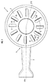
図1及び図2を参照して、1はコンロ用バーナのバーナボディである。このバーナボディ1には混合管2が一体成形され、混合管2の先端のバーナボディ1の部分に、上向きに開口する環状のガス分布室3が形成されている。そして、ガス分布室3を上方から覆うバーナキャップ4を設け、このバーナキャップ4の上面に、周方向の間隔を存して放射状に複数の炎孔5を配置し、各炎孔5から周方向一方(図1で反時計方向)に向かう運動成分を持つ状態でガスを噴出させるようにしている。
1 and 2, reference numeral 1 denotes a burner body of a stove burner. A
バーナキャップ4は、バーナボディ1上に載置される環状の下板部材6と、下板部材6上に載置される環状の上板部材7とで構成される。下板部材6は鍛造品であって、下板部材6の内周には筒部61が垂設されている。そして、この筒部61をガス分布室3の内周壁部に内嵌させることにより、下板部材6がバーナボディ1に対し芯決めされた状態で載置される。また、上板部材7は板金製であって、上板部材7の内周に、下板部材6の筒部61に内嵌する内筒部71を曲成すると共に、上板部材7の外周に、下板部材6の段付き形状の外周部の段部に着座する段部72aを有する段付き形状の外筒部72を曲成している。
The burner cap 4 includes an annular lower plate member 6 placed on the burner body 1 and an annular
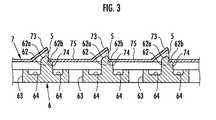
下板部材6には、図3、図4に示す如く、上方に突出する突条62が周方向の間隔を存して放射状に複数突設されている。各突条62の上端面62aは周方向一方(図3の右方)に向けて斜め上向きに傾斜する傾斜面に形成されている。また、上板部材7には、図3に示す如く、周方向一方に向けて斜め上向きに傾斜し、各突条62の上端面62aに隙間を存して平行に対向する切起し部73が周方向の間隔を存して放射状に複数形成されている。かくして、各突条62の上端面62aと各切起し部73との間の隙間で上記各炎孔5が構成される。
As shown in FIG. 3 and FIG. 4, the lower plate member 6 is provided with a plurality of
下板部材6には、更に、各突条62,62間に位置させて、連通孔63が開設されている。そして、ガス分布室3内のガスが各連通孔63を通して該各連通孔63の周方向一方(図3の右方)に位置する各炎孔5に導かれ、各炎孔5から周方向一方に向けて斜め上向きにガスが噴出されるようにしている。かくして、バーナキャップ4の上方に旋回炎が形成され、コンロの天板上の五徳に載置する被加熱物が効率良く加熱される。
The lower plate member 6 is further provided with a
尚、切起し部73は、突条62の上端面62aの周方向一方の端縁の直上位置から周方向一方に若干張り出している。そのため、炎孔5に煮こぼれ汁が侵入しにくくなるが、炎孔5への煮こぼれ汁の侵入を完全に防止することはできない。
Note that the cut-and-raised
そこで、本実施形態では、下板部材6の各連通孔63,63間の部分の上面に、各連通孔63の孔縁部の上端より低い窪み部64を形成し、各窪み部64に、該各窪み部64の周方向両側の連通孔63,63から周方向に離隔させて各突条62を突設している。かくして、各連通孔63とその周方向一方(図3の右方)に位置する各突条62との間に窪み部64が存在すると共に、各連通孔63とその周方向他方(図3の左方)に位置する各突条62との間にも窪み部64が存在することになる。
Therefore, in the present embodiment, a
また、各突条62の周方向一方の側面には、上向きの段部62bが形成されている。そして、各連通孔63の周方向一方に位置する各切起し部73の基端と各連通孔63の周方向他方に位置する各切起し部73の切起し跡の端縁74との間に延在する上板部材7の平坦部75を、各連通孔63の周方向他方に位置する各突条62の段部62bに、切起し跡の端縁74寄りの部分において着座させ、切起し跡の端縁74を突条62の周方向一方の側面の段部62bからの立上り部に当接させている。これにより、下板部材6に対し上板部材7が周方向に位置決めされた状態で支持される。また、各切起し部73の基端は、各連通孔63とその周方向一方に位置する各突条62との間の窪み部64の周方向幅内に位置している。尚、段部62bは、連通孔63の孔縁部と上板部材7の平坦部75との間にガスが流れる間隙が確保されるように、連通孔63の孔縁部より高い位置に形成されている。
Further, an upward
ここで、各連通孔63の周方向一方に位置する各突条62と各切起し部73との間の隙間で構成される各炎孔5から煮こぼれ汁が侵入し、或いは、各連通孔63の周方向他方に位置する各突条62の段部62bとこれに着座する上板部材7の部分との間に生ずる僅かな隙間から毛細管現象で煮こぼれ汁が侵入しても、各連通孔63とその周方向一方に位置する各突条62との間及び各連通孔63とその周方向他方に位置する各突条62との間には上記の如く窪み部64が存在するため、煮こぼれ汁は窪み部64で受け止められる。また、煮こぼれ汁が切起し部73の下面を伝って侵入しても、この煮こぼれ汁は切起し部73の基端から滴下して、連通孔63とその周方向一方に位置する突条62との間の窪み部64に落下する。従って、煮こぼれ汁が連通孔63を通してバーナボディ1内に落下することが防止される。そして、窪み部64に溜まった煮こぼれ汁は、上板部材7を取外して下板部材6を清掃することにより簡単に除去でき、メンテナンス性も良好になる。
Here, boiled juice enters from each
以上、本発明の実施形態について図面を参照して説明したが、本発明はこれに限定されない。例えば、上記実施形態では、ガス分布室3を環状に形成したが、非環状のガス分布室を形成しても良い。また、上記実施形態では、突条62の周方向一方の側面に段部62bを形成したが、段部62を形成せずに、上板部材7の切起し跡の端縁74を突条62の周方向一方の側面に単純に当接させることも可能である。但し、突条62と切起し跡の端縁74との当接部からのガス漏れを防止するには、上記実施形態の如く段部62bに上板部材7の平坦部75を着座させて、ガスシール性を確保することが望ましい。
As mentioned above, although embodiment of this invention was described with reference to drawings, this invention is not limited to this. For example, in the above embodiment, the
また、連通孔63とその周方向他方に位置する突条62との間の窪み部64が埋まるように突条62を形成し、段部62bの周方向幅を広くすることも可能である。然し、これでは、段部62bと上板部材7の平坦部75との間に生ずる僅かな隙間から毛細管現象で煮こぼれ汁が侵入して、連通孔63からバーナボディ1内に煮こぼれ汁が落下する可能性がある。従って、バーナボディ1内への煮こぼれ汁の落下を確実に防止するには、上記実施形態のように構成することが望ましい。また、上記実施形態では、下板部材6を鍛造品としたが、金属板を上記実施形態の下板部材6の上面に沿う形状にプレス成形した板金製の下板部材を用いることも可能である。
Moreover, it is also possible to form the
1…バーナボディ、3…ガス分布室、4…バーナキャップ、5…炎孔、6…下板部材、62…突条、62a…上端面、62b…段部、63…連通孔、64…窪み部、7…上板部材、73…切起し部、74…切起し跡の端縁。
DESCRIPTION OF SYMBOLS 1 ... Burner body, 3 ... Gas distribution chamber, 4 ... Burner cap, 5 ... Flame hole, 6 ... Lower plate member, 62 ... Projection, 62a ... Upper end surface, 62b ... Step part, 63 ... Communication hole, 64 ...
Claims (3)
バーナキャップは、下板部材と、下板部材上に載置する上板部材とで構成され、下板部材に、上方に突出する突条が周方向の間隔を存して放射状に複数突設され、上板部材に、各突条の上端面に隙間を存して対向する切起し部が周方向の間隔を存して放射状に複数形成され、各突条の上端面と各切起し部との間の隙間で各炎孔が構成されると共に、下板部材に各突条間に位置させて連通孔が開設され、ガス分布室内のガスが各連通孔を通して該各連通孔の周方向一方に位置する各炎孔に導かれるようにしたものにおいて、
下板部材の各連通孔間の部分の上面に、各連通孔の孔縁部の上端より低い窪み部が形成され、この窪み部が各連通孔と該各連通孔の周方向一方に位置する各突条との間に存在することを特徴とするコンロ用バーナ。 A burner cap that covers the upwardly opening gas distribution chamber formed in the burner body is provided from above, and a plurality of flame holes are arranged radially on the upper surface of the burner cap with a circumferential interval therebetween. A burner for a stove in which gas is ejected in a state having a motion component toward one direction,
The burner cap is composed of a lower plate member and an upper plate member placed on the lower plate member, and a plurality of protrusions protruding upward are radially provided on the lower plate member with a circumferential interval therebetween. The upper plate member is formed with a plurality of radiating portions facing each other with a gap in the upper end surface of each ridge with a gap in the circumferential direction. Each flame hole is formed by a gap between the bottom and the bottom plate member, and a communication hole is established between each protrusion on the lower plate member, and gas in the gas distribution chamber passes through each communication hole. In what was led to each flame hole located in one circumferential direction,
On the upper surface of the portion between the communication holes of the lower plate member, a recess is formed that is lower than the upper end of the hole edge of each communication hole, and this recess is located in one circumferential direction of each communication hole and each communication hole. A stove burner characterized by existing between each protrusion.
Priority Applications (3)
| Application Number | Priority Date | Filing Date | Title |
|---|---|---|---|
| JP2005266237A JP4150034B2 (en) | 2005-09-14 | 2005-09-14 | Stove burner |
| TW095120395A TW200712379A (en) | 2005-09-14 | 2006-06-08 | Burner for gas stove |
| CN2006101261610A CN1932383B (en) | 2005-09-14 | 2006-08-28 | Combustor for stove |
Applications Claiming Priority (1)
| Application Number | Priority Date | Filing Date | Title |
|---|---|---|---|
| JP2005266237A JP4150034B2 (en) | 2005-09-14 | 2005-09-14 | Stove burner |
Publications (2)
| Publication Number | Publication Date |
|---|---|
| JP2007078241A JP2007078241A (en) | 2007-03-29 |
| JP4150034B2 true JP4150034B2 (en) | 2008-09-17 |
Family
ID=37878341
Family Applications (1)
| Application Number | Title | Priority Date | Filing Date |
|---|---|---|---|
| JP2005266237A Expired - Fee Related JP4150034B2 (en) | 2005-09-14 | 2005-09-14 | Stove burner |
Country Status (3)
| Country | Link |
|---|---|
| JP (1) | JP4150034B2 (en) |
| CN (1) | CN1932383B (en) |
| TW (1) | TW200712379A (en) |
Families Citing this family (4)
| Publication number | Priority date | Publication date | Assignee | Title |
|---|---|---|---|---|
| JP6297994B2 (en) * | 2015-02-24 | 2018-03-20 | リンナイ株式会社 | Gas stove |
| CN110779048B (en) * | 2019-11-13 | 2021-07-27 | 山东德浦泰管业科技有限公司 | A natural gas gas stove for preventing fire source from extinguishing |
| CN119492049B (en) * | 2023-08-21 | 2026-04-03 | 芜湖美的智能厨电制造有限公司 | Burners and stoves |
| WO2025040101A1 (en) * | 2023-08-21 | 2025-02-27 | 芜湖美的智能厨电制造有限公司 | Burner, burner assembly and range |
Family Cites Families (3)
| Publication number | Priority date | Publication date | Assignee | Title |
|---|---|---|---|---|
| CN86210833U (en) * | 1986-12-28 | 1988-02-10 | 张海喜 | Enhanced gas cooking stove |
| JPH11211024A (en) * | 1998-01-21 | 1999-08-06 | Matsushita Electric Ind Co Ltd | Gas stove burner |
| CN2342263Y (en) * | 1998-10-20 | 1999-10-06 | 林永忠 | Blind integrated pot frame |
-
2005
- 2005-09-14 JP JP2005266237A patent/JP4150034B2/en not_active Expired - Fee Related
-
2006
- 2006-06-08 TW TW095120395A patent/TW200712379A/en not_active IP Right Cessation
- 2006-08-28 CN CN2006101261610A patent/CN1932383B/en not_active Expired - Fee Related
Also Published As
| Publication number | Publication date |
|---|---|
| TW200712379A (en) | 2007-04-01 |
| CN1932383A (en) | 2007-03-21 |
| TWI313338B (en) | 2009-08-11 |
| CN1932383B (en) | 2010-09-29 |
| JP2007078241A (en) | 2007-03-29 |
Similar Documents
| Publication | Publication Date | Title |
|---|---|---|
| US6389961B1 (en) | Grill plate | |
| ES2875008T3 (en) | Gas burner, gas hob and gas cooking appliance | |
| KR20110102224A (en) | Combination oil ring | |
| US9848730B2 (en) | Food carrier and grilling accessory | |
| JP4150034B2 (en) | Stove burner | |
| USD1016323S1 (en) | Microfluidic slab | |
| JP6763974B2 (en) | Plate heat exchanger | |
| KR20140023299A (en) | Piston for an internal combustion engine | |
| EP3299716A1 (en) | Burner for gas apparatus | |
| CA2508396A1 (en) | Juicer and grater assembly | |
| KR20100048458A (en) | Gas burner | |
| CA2615175A1 (en) | Candle assembly including a fuel element with a locating recess and a melting plate with a locating protrusion | |
| JP3984238B2 (en) | Stove burner | |
| EP3224153B1 (en) | Beverage container lid | |
| DE602009000429D1 (en) | Induction heated cooking utensils and manufacturing processes | |
| JP6400964B2 (en) | Stove burner | |
| FR2944730B1 (en) | STAMPING TOOL FOR THERMOPLASTIC PARTS AND METHOD. | |
| JP3940317B2 (en) | Gas stove | |
| KR200428072Y1 (en) | Thermal barrier device of portable gas burner | |
| JP2004232974A (en) | Trivet for glass top cooking stove | |
| US20170246666A1 (en) | Cleaning device for microwave oven | |
| KR20130005392U (en) | Meat roaster | |
| JP4146847B2 (en) | Stove burner | |
| US859659A (en) | Attachment to vapor-stoves. | |
| JP7643906B2 (en) | Gas range mat |
Legal Events
| Date | Code | Title | Description |
|---|---|---|---|
| A621 | Written request for application examination |
Free format text: JAPANESE INTERMEDIATE CODE: A621 Effective date: 20070704 |
|
| A977 | Report on retrieval |
Free format text: JAPANESE INTERMEDIATE CODE: A971007 Effective date: 20080605 |
|
| TRDD | Decision of grant or rejection written | ||
| A01 | Written decision to grant a patent or to grant a registration (utility model) |
Free format text: JAPANESE INTERMEDIATE CODE: A01 Effective date: 20080624 |
|
| A01 | Written decision to grant a patent or to grant a registration (utility model) |
Free format text: JAPANESE INTERMEDIATE CODE: A01 |
|
| A61 | First payment of annual fees (during grant procedure) |
Free format text: JAPANESE INTERMEDIATE CODE: A61 Effective date: 20080626 |
|
| FPAY | Renewal fee payment (event date is renewal date of database) |
Free format text: PAYMENT UNTIL: 20110704 Year of fee payment: 3 |
|
| R150 | Certificate of patent or registration of utility model |
Free format text: JAPANESE INTERMEDIATE CODE: R150 |
|
| FPAY | Renewal fee payment (event date is renewal date of database) |
Free format text: PAYMENT UNTIL: 20120704 Year of fee payment: 4 |
|
| FPAY | Renewal fee payment (event date is renewal date of database) |
Free format text: PAYMENT UNTIL: 20130704 Year of fee payment: 5 |
|
| R250 | Receipt of annual fees |
Free format text: JAPANESE INTERMEDIATE CODE: R250 |
|
| R250 | Receipt of annual fees |
Free format text: JAPANESE INTERMEDIATE CODE: R250 |
|
| R250 | Receipt of annual fees |
Free format text: JAPANESE INTERMEDIATE CODE: R250 |
|
| R250 | Receipt of annual fees |
Free format text: JAPANESE INTERMEDIATE CODE: R250 |
|
| R250 | Receipt of annual fees |
Free format text: JAPANESE INTERMEDIATE CODE: R250 |
|
| LAPS | Cancellation because of no payment of annual fees |