JP4154355B2 - ディスクの誤挿入防止機構 - Google Patents
ディスクの誤挿入防止機構 Download PDFInfo
- Publication number
- JP4154355B2 JP4154355B2 JP2004080462A JP2004080462A JP4154355B2 JP 4154355 B2 JP4154355 B2 JP 4154355B2 JP 2004080462 A JP2004080462 A JP 2004080462A JP 2004080462 A JP2004080462 A JP 2004080462A JP 4154355 B2 JP4154355 B2 JP 4154355B2
- Authority
- JP
- Japan
- Prior art keywords
- arm
- disc
- rotating arm
- disk
- front plate
- Prior art date
- Legal status (The legal status is an assumption and is not a legal conclusion. Google has not performed a legal analysis and makes no representation as to the accuracy of the status listed.)
- Expired - Fee Related
Links
- 238000003780 insertion Methods 0.000 title claims description 83
- 230000007246 mechanism Effects 0.000 title claims description 42
- 230000002265 prevention Effects 0.000 title claims description 18
- 230000037431 insertion Effects 0.000 claims description 80
- 238000005452 bending Methods 0.000 claims description 15
- 230000002093 peripheral effect Effects 0.000 claims description 14
- 230000007723 transport mechanism Effects 0.000 claims description 8
- 239000002184 metal Substances 0.000 claims description 6
- 238000000034 method Methods 0.000 claims 1
- 230000032258 transport Effects 0.000 description 8
- 238000000926 separation method Methods 0.000 description 5
- 238000001514 detection method Methods 0.000 description 3
- 230000003287 optical effect Effects 0.000 description 1
Images


Landscapes
- Feeding And Guiding Record Carriers (AREA)
Description
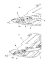
また、前記回動アームが金属板製の回動アームからなると共に、この回動アームの一側縁に前面板の外表面に対して起立方向へ突出する折曲湾曲部を形成し、回動アームが挿入口の閉塞位置にあるとき、該挿入口の長手方向に沿う直線に対して折曲湾曲部を傾斜させた構成とした。このような構成とすることにより、回動アームの機械的強度を折曲湾曲部によって高めることができると共に、ディスクのイジェクト時に、挿入口内で傾斜している折曲湾曲部の裏面側にディスクの外周縁が当接して回動アームを回動させるため、ディスクの損傷を防止することができる。
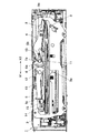
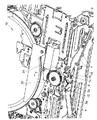
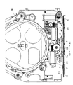
2 ノーズ部材
2a 開口
3 前面板
3a 挿入口
4 第1の回動アーム
4a ギヤ部
4b 折曲湾曲部
5 第2の回動アーム
5a ギヤ部
5b 折曲湾曲部
6 クラッチ板
7 駆動部材
7a 突部
8 ストッパ
9 板ばね(弾性手段)
9a 摺動部
10 スプリング
11,12 ピン
13 捻りコイルばね
18 ディスク搬送機構
19 ディスク収納部
21 モータ
22 ホイールギヤ
23 スライドアーム
23a ラック部
23b 作動突起
Claims (7)
- ディスクを挿入および排出するためのスリット状の挿入口が設けられた前面板と、前記挿入口とプレイ位置間でディスクを搬送するディスク搬送機構と、前記前面板の外表面に沿って回動可能な金属板製の回動アームと、この回動アームの回動軌跡内に配設されたストッパと、前記回動アームを前記前面板の外表面から離間する方向へ付勢して前記ストッパとの当接を回避する弾性手段と、前記回動アームを回転駆動して前記挿入口を選択的に開閉する開放手段とを備え、前記回動アームの一側縁に前記前面板の外表面に対して起立方向へ突出する折曲湾曲部を形成し、前記回動アームが前記挿入口の閉塞位置にあるとき、該挿入口の長手方向に沿う直線に対して前記折曲湾曲部が傾斜して対向するようにし、
前記挿入口の閉塞位置にある前記回動アームに向けてディスクが挿入されたとき、該ディスクの外周縁が前記回動アームの前記折曲湾曲部の前端縁に当接して該回動アームが前記弾性手段の付勢力に抗して前記前面板の外表面側に押し付けられて前記ストッパと当接することにより、該回動アームの回転が阻止されると共に、前記ディスク搬送機構によりディスクが排出されるとき、該ディスクの外周縁が前記閉塞位置にある前記回動アームの前記折曲湾曲部の裏面側に当接して該回動アームを開放方向に回動させるように構成したことを特徴とするディスクの誤挿入防止機構。 - 請求項1の記載において、前記弾性手段が前記回動アームに片持ち梁状に固着された板ばねからなり、この板ばねの自由端部を前記前面板の外表面に弾接させたことを特徴とするディスクの誤挿入防止機構。
- 請求項1の記載において、前記回動アームが前記前面板の外表面に軸支された一対の回動アームからなり、これら回動アームの端部同士をギア結合することにより、前記一対の回動アームが同期して回転するように構成したことを特徴とするディスクの誤挿入防止機構。
- 請求項3の記載において、前記一対の回動アームが前記挿入口の閉塞位置にあるとき、該挿入口の長手方向に沿う直線に対して前記一対の回動アームが逆向きに傾斜するように構成したことを特徴とするディスクの誤挿入防止機構。
- 請求項1の記載において、前記回動アームと前記開放手段との間にクラッチ板を介設し、このクラッチ板を前記回動アームと同軸上に配置すると共に、これら回動アームとクラッチ板とに捻りコイルばねの両端を掛止したことを特徴とするディスクの誤挿入防止機構。
- 請求項1〜5のいずれか1項の記載において、ディスクの周縁部が挿入されるガイド溝を有する搬送ガイド体と、この搬送ガイド体に対向して列状に配置された搬送プーリ群と、これら搬送ガイド体と搬送プーリ群との対向間隔を可変させる可変動力部とを備え、前記開放手段が前記可変動力部を駆動源としてスライド動作する駆動部材であると共に、この駆動部材の一部を前面板の裏面側から外表面側に突出させたことを特徴とするディスクの誤挿入防止機構。
- 請求項6の記載において、前記可変動力部が前記搬送ガイド体と前記搬送プーリ群との対向間隔を最小にさせるとき、前記駆動部材のスライド移動に伴って前記回動アームが前記挿入口の閉塞位置から開放位置へと回動することを特徴とするディスクの誤挿入防止機構。
Priority Applications (1)
| Application Number | Priority Date | Filing Date | Title |
|---|---|---|---|
| JP2004080462A JP4154355B2 (ja) | 2004-03-19 | 2004-03-19 | ディスクの誤挿入防止機構 |
Applications Claiming Priority (1)
| Application Number | Priority Date | Filing Date | Title |
|---|---|---|---|
| JP2004080462A JP4154355B2 (ja) | 2004-03-19 | 2004-03-19 | ディスクの誤挿入防止機構 |
Publications (2)
| Publication Number | Publication Date |
|---|---|
| JP2005267781A JP2005267781A (ja) | 2005-09-29 |
| JP4154355B2 true JP4154355B2 (ja) | 2008-09-24 |
Family
ID=35092148
Family Applications (1)
| Application Number | Title | Priority Date | Filing Date |
|---|---|---|---|
| JP2004080462A Expired - Fee Related JP4154355B2 (ja) | 2004-03-19 | 2004-03-19 | ディスクの誤挿入防止機構 |
Country Status (1)
| Country | Link |
|---|---|
| JP (1) | JP4154355B2 (ja) |
Families Citing this family (2)
| Publication number | Priority date | Publication date | Assignee | Title |
|---|---|---|---|---|
| JP2007293981A (ja) | 2006-04-24 | 2007-11-08 | Teac Corp | ディスク装置 |
| JP5079376B2 (ja) * | 2007-04-12 | 2012-11-21 | アルパイン株式会社 | ディスクプレーヤの誤挿入防止機構 |
-
2004
- 2004-03-19 JP JP2004080462A patent/JP4154355B2/ja not_active Expired - Fee Related
Also Published As
| Publication number | Publication date |
|---|---|
| JP2005267781A (ja) | 2005-09-29 |
Similar Documents
| Publication | Publication Date | Title |
|---|---|---|
| JP3816010B2 (ja) | ディスク装置 | |
| JPWO2005101401A1 (ja) | ディスク装置 | |
| JP4154355B2 (ja) | ディスクの誤挿入防止機構 | |
| US6081494A (en) | Disc recording and reproducing apparatus having a drive mechanism for loading and ejecting a disc cartridge | |
| JP4272652B2 (ja) | ディスクの誤挿入防止機構 | |
| JP4493714B2 (ja) | ディスクプレーヤ | |
| JP4948987B2 (ja) | ディスク装置 | |
| JP4197146B2 (ja) | ディスク装置 | |
| JP2008097777A (ja) | ディスクの誤挿入防止機構 | |
| US5881040A (en) | Disc device with slider contact prevention mechanism | |
| JP5079376B2 (ja) | ディスクプレーヤの誤挿入防止機構 | |
| JP3658078B2 (ja) | 記録再生装置 | |
| JP2006172522A (ja) | ディスクカートリッジ | |
| JP4949461B2 (ja) | 光ディスク装置 | |
| JP3551629B2 (ja) | 記録媒体再生装置 | |
| JP2004318965A (ja) | シャッター装置 | |
| JP3812317B2 (ja) | カートリッジ装着装置 | |
| JPH11213506A (ja) | ディスク装置 | |
| JP4264402B2 (ja) | 記録媒体装着装置 | |
| JP4525482B2 (ja) | ディスク駆動装置及び電子機器 | |
| JP2000123456A (ja) | ディスクドライブ装置 | |
| JP3473619B2 (ja) | ミニディスク及びコンパクトディスクの兼用ディスクプレーヤ | |
| JP2602458Y2 (ja) | カートリッジ吸引機構 | |
| JP3817553B2 (ja) | 情報記録媒体再生装置 | |
| JPH11213505A (ja) | ディスク装置 |
Legal Events
| Date | Code | Title | Description |
|---|---|---|---|
| A621 | Written request for application examination |
Free format text: JAPANESE INTERMEDIATE CODE: A621 Effective date: 20060809 |
|
| A977 | Report on retrieval |
Free format text: JAPANESE INTERMEDIATE CODE: A971007 Effective date: 20080213 |
|
| A131 | Notification of reasons for refusal |
Free format text: JAPANESE INTERMEDIATE CODE: A131 Effective date: 20080219 |
|
| A521 | Request for written amendment filed |
Free format text: JAPANESE INTERMEDIATE CODE: A523 Effective date: 20080415 |
|
| TRDD | Decision of grant or rejection written | ||
| A01 | Written decision to grant a patent or to grant a registration (utility model) |
Free format text: JAPANESE INTERMEDIATE CODE: A01 Effective date: 20080624 |
|
| A01 | Written decision to grant a patent or to grant a registration (utility model) |
Free format text: JAPANESE INTERMEDIATE CODE: A01 |
|
| A61 | First payment of annual fees (during grant procedure) |
Free format text: JAPANESE INTERMEDIATE CODE: A61 Effective date: 20080707 |
|
| R150 | Certificate of patent or registration of utility model |
Free format text: JAPANESE INTERMEDIATE CODE: R150 Ref document number: 4154355 Country of ref document: JP Free format text: JAPANESE INTERMEDIATE CODE: R150 |
|
| FPAY | Renewal fee payment (event date is renewal date of database) |
Free format text: PAYMENT UNTIL: 20110711 Year of fee payment: 3 |
|
| FPAY | Renewal fee payment (event date is renewal date of database) |
Free format text: PAYMENT UNTIL: 20120711 Year of fee payment: 4 |
|
| FPAY | Renewal fee payment (event date is renewal date of database) |
Free format text: PAYMENT UNTIL: 20120711 Year of fee payment: 4 |
|
| FPAY | Renewal fee payment (event date is renewal date of database) |
Free format text: PAYMENT UNTIL: 20130711 Year of fee payment: 5 |
|
| FPAY | Renewal fee payment (event date is renewal date of database) |
Free format text: PAYMENT UNTIL: 20130711 Year of fee payment: 5 |
|
| FPAY | Renewal fee payment (event date is renewal date of database) |
Free format text: PAYMENT UNTIL: 20140711 Year of fee payment: 6 |
|
| LAPS | Cancellation because of no payment of annual fees |