JP4172016B2 - Scaffolding insert and its construction method - Google Patents
Scaffolding insert and its construction method Download PDFInfo
- Publication number
- JP4172016B2 JP4172016B2 JP2003174935A JP2003174935A JP4172016B2 JP 4172016 B2 JP4172016 B2 JP 4172016B2 JP 2003174935 A JP2003174935 A JP 2003174935A JP 2003174935 A JP2003174935 A JP 2003174935A JP 4172016 B2 JP4172016 B2 JP 4172016B2
- Authority
- JP
- Japan
- Prior art keywords
- joint
- insert
- wall
- insert body
- scaffold
- Prior art date
- Legal status (The legal status is an assumption and is not a legal conclusion. Google has not performed a legal analysis and makes no representation as to the accuracy of the status listed.)
- Expired - Fee Related
Links
Images


Landscapes
- Forms Removed On Construction Sites Or Auxiliary Members Thereof (AREA)
Description
【0001】
【発明の属する技術分野】
本発明は、建物の施工に際して外壁に打ち込まれる足場用インサートおよびその施工方法に関する。
【0002】
【従来の技術】
周知のように、RC造の建物の施工に際して外壁に面して足場を設ける場合、足場の転倒を防止するために壁繋ぎ材によって外壁に連結する必要があり、そのため、外壁の施工に際しては壁繋ぎ材を取り付けるためのインサートを打ち込む必要がある。そのような足場用のインサートしては各種のものが提案されており、たとえば特許文献1には、外壁を形成するための型枠に貫通孔を設けて、その内側に可撓係止片を有する支持部材を配するとともに、型枠の外側にはバネにより押圧されるワッシャを設け、それら可撓係止片とワッシャとにより型枠を狭持した状態で取り付けるようにした足場用インサートが開示されている。
【0003】
【特許文献1】
実開平6−35508号公報
【0004】
【発明が解決しようとする課題】
従来のこの種の足場用インサートは、型枠を挿通する状態で取り付けられるものであることから、足場用インサートを型枠に取り付ける際には型枠に貫通孔を設ける必要があり、その位置決めも含めて取り付け作業が面倒であった。また、足場を解体した後には足場用インサートを隠蔽するための補修と仕上げが必要となるが、そのような補修や仕上げは必ずしも容易に行い得るものではなく、ときとして痕跡が残ってしまうことがあった。
【0005】
上記事情に鑑み、本発明は型枠に対して極めて簡単に取り付けることができ、しかも格別の補修や仕上げを必要としない足場用インサートおよびその施工方法を提供することを目的とする。
【0006】
【課題を解決するための手段】
請求項1の発明は、建物の施工に施工に際してRC造の外壁に打ち込まれる足場用インサートであって、外壁の打継部に打ち込まれるインサート本体と、インサート本体を外壁に定着するための定着部材と、インサート本体を型枠に対して仮止めするための取付部材からなり、インサート本体は長ナットからなり、定着部材は先端部がインサート本体の後端部に螺着されかつ基端部が下方に折り曲げ加工された鋼棒からなり、取付部材はインサート本体の上部に接着されてその先端部が打継目地を形成するための目地棒に仮止めされるプレート材からなることを特徴とする。
【0007】
請求項2の発明は、請求項1の発明の足場用インサートを外壁に打ち込むに際し、外壁を形成するための型枠の内側に打継目地を形成するための目地棒を取り付け、その目地棒にインサート本体の先端を当接させかつ定着部材の基端部を下方に向けた状態で取付部材の先端部を目地棒に仮止めすることによって足場用インサートを型枠内に取り付け、型枠内にコンクリートを打設することによって、インサート本体の先端を打継目地の目地底に開口させる状態で足場用インサートを打継部に打ち込むことを特徴とする。
【0008】
【発明の実施の形態】
図1は本発明の一実施形態である足場用インサート1の概略構成を示す斜視図であって、この足場用インサート1は、インサート本体2と、定着部材3と、取付部材4から構成されている。
【0009】
インサート本体2は足場組み立ての際に壁繋ぎ材を連結するためのもので、本実施形態では長ナットを採用している。長ナットとしては適宜のもので良いが、たとえば汎用の4分ナット、長さ40mmのものが好適に採用可能である。
【0010】
定着部材3はインサート本体2を外壁中に確実強固に定着するためのもので、本実施形態では鋼棒を採用している。定着部材3としての鋼棒としては所望の定着強度が確保できるものであれば適宜のもので良いが、図示例のもののように先端部がインサート本体2の後端部に螺着され基端部が下方に折り曲げ加工されたものが好適であり、そのような鋼棒としてはたとえば汎用の4分セパレータを折り曲げ加工したものが好適に採用可能であり、必要に応じてその基端部に定着ナット5を螺着しておくと良い。なお、定着部材3をインサート本体2に螺着した後には、定着部材3が不用意に回転してしまうことのないようにインサート本体2の後部を機械的に潰してかしめると良い。
【0011】
取付部材4はこの足場用インサート1を目地棒6に対して仮止めするためのもので、本実施形態では金属板の小片等のプレート材が採用されている。この取付部材4は、インサート本体2の上面に接着されて取り付けられ、その先端部はインサート本体2よりも前方に延出しており、そこにはねじ穴8が形成されているとともに、最先端部が下方に折り曲げられて係止部9が形成されている。取付部材4の素材としてはたとえばトタン板の小片(寸法は40mm×60mm程度、肉厚が0.35mmのもの)が好適に採用可能であるが、コンクリート打設時に折れたり外れてしまうことのないように充分な強度を有するものであれば樹脂等の他の素材のものも採用可能である。
【0012】
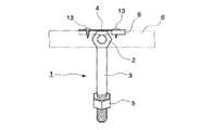
上記構成の足場用インサート1は外壁施工に際してその打継部に打ち込まれるものであり、その施工方法を図2〜図5を参照して説明する。すなわち、外壁形成用の型枠としての堰板11には、打継部に打継目地を設けるために目地棒6を取り付けておき、その目地棒6にインサート本体2の先端を当接させた状態で、取付部材4の最先端部の係止部9を目地棒6と堰板11との間に差し込むとともに、ねじ孔8にねじ13をねじ込んで取付部材4を目地棒6に仮止めし、これにより足場用インサート1を打継部の内側に配置する。
【0013】
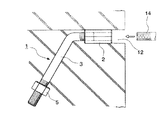
その状態で堰板11の内側に目地棒6の上面のレベルまでコンクリートを打設して足場用インサート1をコンクリート中に埋設し、養生後に堰板11を撤去する。足場の組み立てに際しては、図5に示すように足場用インサート1の前部にある目地棒6を切除してインサート本体2の先端を打継目地12の目地底に露出させ、それに壁繋ぎ材14を連結する。なお、目地棒6を切除する際には、それにねじ止めされている取付部材4も一緒に撤去すれば良いが、取付部材4を必要に応じて折り曲げる等の処理をして残置しても良い。取付部材4を撤去する場合には、インサート本体2に接着されているだけなので、ハンマー等により殴打することで容易に剥離させて撤去することができるし、折り曲げて残置する場合も薄いプレート材であるので容易に折り曲げることができる。
【0014】
図5に示すように上階にコンクリートを打ち継いでいき、外壁の仕上げに際しては足場を解体しつつ目地棒6を全て撤去し、適宜の目地材を充填する等して打継目地12を完成させる。
【0015】
本実施形態の足場用インサート1は、外壁の打継部に打ち込まれるものであるので、これを打ち込むに際しては従来のように型枠に貫通孔を設けるような必要がなく、堰板11の内側に取り付けられる目地棒6にねじ止めすることのみで極めて簡単に打ち込むことができる。また、インサート本体2は打継目地12の目地底に開口する状態で打ち込まれるので、外壁の仕上げに際して打継目地12に目地材が充填されることで自ずと足場用インサート1は隠蔽されてしまい、したがって格別の補修や仕上げのための作業を必要としないし、従来のように痕跡が残って仕上げを損なうようなこともない。勿論、この足場用インサート1は何等複雑なものではなく汎用の長ナットと鋼棒およびプレート材のみで簡単かつ充分に安価に製作することができる。
【0016】
なお、以上の実施形態はあくまで一例であって、本発明は上記実施形態に限定されるものでは勿論なく、インサート本体や定着部材、取付部材等の形状、寸法、素材その他の構成、およびそれを用いた外壁施工手順等については、上記で例示した以外にも適宜の設計的変更が可能であることは当然である。
【0017】
【発明の効果】
請求項1の発明の足場用インサートは、長ナットからなるインサート本体と、鋼棒からなる定着部材と、プレート材からなる取付部材からなり、取付部材を目地棒に仮止めすることで打継部に打ち込む構成であるので、構成が簡単で安価に製作することができ、型枠に対して極めて簡単に取り付けることができ、外壁の仕上げに際して打継目地に目地材を充填することで自ずと隠蔽されてしまうので格別な補修や仕上げを必要としない、という優れた効果を有する。
【0018】
請求項2の発明の施工方法は、上記の足場用インサートを目地棒に取り付け、インサート本体の先端を打継目地の目地底に開口させる状態で打ち込むようにしたので、型枠に対する取り付けを容易に行うことができるし、打継目地に目地材を充填することのみで足場用インサートを自ずと隠蔽してしまうことができるから、外壁仕上げに際して格別な補修や仕上げを必要としない、という優れた効果を有する。
【図面の簡単な説明】
【図1】 本発明の足場用インサートの一実施形態を示す斜視図である。
【図2】 同、型枠に取り付けた状態を示す側面図である。
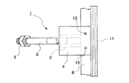
【図3】 同、正面図である。
【図4】 同、平面図である。
【図5】 同、コンクリートに打ち込んだ状態を示す側面図である。
【符号の説明】
1 足場用インサート
2 インサート本体(長ナット)
3 定着部材(鋼棒)
4 取付部材(プレート材)
5 定着ナット
6 目地棒
8 ねじ孔
9 係止部
11 堰板(型枠)
12 打継目地
13 ねじ
14 壁繋ぎ材[0001]
BACKGROUND OF THE INVENTION
The present invention relates to an insert for scaffolding that is driven into an outer wall during construction of a building and a construction method thereof.
[0002]
[Prior art]
As is well known, when installing a scaffold facing the outer wall when constructing an RC building, it is necessary to connect it to the outer wall with a wall connecting material to prevent the scaffold from falling down. It is necessary to drive in an insert for attaching the connecting material. Various types of inserts for such scaffolds have been proposed. For example, in
[0003]
[Patent Document 1]
Japanese Utility Model Publication No. 6-35508 [0004]
[Problems to be solved by the invention]
Since this type of conventional scaffolding insert is attached in a state of being inserted through the formwork, when attaching the scaffolding insert to the formwork, it is necessary to provide a through hole in the formwork, and its positioning is also Installation work including it was troublesome. In addition, after dismantling the scaffold, repair and finishing are necessary to conceal the insert for the scaffold, but such repair and finishing are not always easy to perform, and traces sometimes remain. there were.
[0005]
In view of the above circumstances, an object of the present invention is to provide an insert for a scaffold that can be attached to a mold extremely easily and does not require special repair or finishing, and a construction method thereof.
[0006]
[Means for Solving the Problems]
The invention according to
[0007]
In the invention of
[0008]
DETAILED DESCRIPTION OF THE INVENTION
FIG. 1 is a perspective view showing a schematic configuration of a
[0009]
The insert
[0010]
The
[0011]
The
[0012]
The scaffold insert 1 having the above-described structure is driven into the joint portion when the outer wall is constructed, and the construction method will be described with reference to FIGS. That is, a
[0013]
In this state, concrete is cast up to the level of the upper surface of the
[0014]
As shown in FIG. 5, concrete is handed over to the upper floor, and when finishing the outer wall, the
[0015]
Since the scaffold insert 1 of this embodiment is driven into the joint portion of the outer wall, there is no need to provide a through-hole in the mold as in the prior art, and the inside of the
[0016]
The above embodiment is merely an example, and the present invention is not limited to the above embodiment, and the shape, dimensions, material and other configurations of the insert body, the fixing member, the mounting member, etc. As for the used outer wall construction procedure and the like, it is a matter of course that appropriate design changes can be made in addition to those exemplified above.
[0017]
【The invention's effect】
The insert for scaffolding of the invention of
[0018]
In the construction method of the invention of
[Brief description of the drawings]
FIG. 1 is a perspective view showing an embodiment of a scaffold insert according to the present invention.
FIG. 2 is a side view showing a state of being attached to the mold.
FIG. 3 is a front view of the same.
FIG. 4 is a plan view of the same.
FIG. 5 is a side view showing a state of being driven into concrete.
[Explanation of symbols]
1
3 Fixing member (steel bar)
4 Mounting member (plate material)
5 Fixing
12
Claims (2)
Priority Applications (1)
| Application Number | Priority Date | Filing Date | Title |
|---|---|---|---|
| JP2003174935A JP4172016B2 (en) | 2003-06-19 | 2003-06-19 | Scaffolding insert and its construction method |
Applications Claiming Priority (1)
| Application Number | Priority Date | Filing Date | Title |
|---|---|---|---|
| JP2003174935A JP4172016B2 (en) | 2003-06-19 | 2003-06-19 | Scaffolding insert and its construction method |
Publications (2)
| Publication Number | Publication Date |
|---|---|
| JP2005009183A JP2005009183A (en) | 2005-01-13 |
| JP4172016B2 true JP4172016B2 (en) | 2008-10-29 |
Family
ID=34098277
Family Applications (1)
| Application Number | Title | Priority Date | Filing Date |
|---|---|---|---|
| JP2003174935A Expired - Fee Related JP4172016B2 (en) | 2003-06-19 | 2003-06-19 | Scaffolding insert and its construction method |
Country Status (1)
| Country | Link |
|---|---|
| JP (1) | JP4172016B2 (en) |
Families Citing this family (1)
| Publication number | Priority date | Publication date | Assignee | Title |
|---|---|---|---|---|
| JP2019052518A (en) * | 2017-09-15 | 2019-04-04 | 野村建設工業株式会社 | Insert for scaffold |
-
2003
- 2003-06-19 JP JP2003174935A patent/JP4172016B2/en not_active Expired - Fee Related
Also Published As
| Publication number | Publication date |
|---|---|
| JP2005009183A (en) | 2005-01-13 |
Similar Documents
| Publication | Publication Date | Title |
|---|---|---|
| JP2005009183A (en) | Scaffolding insert and its construction method | |
| JP4026077B2 (en) | Scaffolding bracket | |
| JP3742504B2 (en) | Protective fence | |
| JPH08326304A (en) | Scaffold mounting structure | |
| JP3748766B2 (en) | Repair method and repair metal fittings for concrete structures | |
| KR200432863Y1 (en) | Handrail Pipe Joint Structure | |
| JP2971061B1 (en) | Anchor bolt holding device for foundation when placing concrete | |
| JP2001348883A (en) | Inspection opening structure for house foundation and its construction method | |
| JPS621056B2 (en) | ||
| JP3023601B2 (en) | Handrail renovation method | |
| JP2000027429A (en) | Hardware for fixing scaffolds | |
| JP2005048392A (en) | Handrail column installing device | |
| KR200383204Y1 (en) | Combination structure of parapet | |
| JP3048453B2 (en) | Exterior material mounting method | |
| JP6692722B2 (en) | Sash mounting structure and sash mounting method | |
| JPH057847U (en) | Formwork support | |
| JPH0261245A (en) | Formation of hollow slab and pipe fitting tool therefor | |
| JPH0339533Y2 (en) | ||
| JPH07947B2 (en) | Prefabricated wall misalignment assisting tool and method of assembling prefabricated wall using the assistive tool | |
| JPH06248785A (en) | Dry construction method for pasting building materials | |
| JPH0512525U (en) | Rain gutter support | |
| JPH0227041Y2 (en) | ||
| JP2019052518A (en) | Insert for scaffold | |
| JP2001262740A (en) | Building wall panel body | |
| JPH0522739U (en) | Stair handrail mounting structure |
Legal Events
| Date | Code | Title | Description |
|---|---|---|---|
| A621 | Written request for application examination |
Free format text: JAPANESE INTERMEDIATE CODE: A621 Effective date: 20060301 |
|
| A977 | Report on retrieval |
Free format text: JAPANESE INTERMEDIATE CODE: A971007 Effective date: 20080201 |
|
| TRDD | Decision of grant or rejection written | ||
| A01 | Written decision to grant a patent or to grant a registration (utility model) |
Free format text: JAPANESE INTERMEDIATE CODE: A01 Effective date: 20080715 |
|
| A01 | Written decision to grant a patent or to grant a registration (utility model) |
Free format text: JAPANESE INTERMEDIATE CODE: A01 |
|
| A61 | First payment of annual fees (during grant procedure) |
Free format text: JAPANESE INTERMEDIATE CODE: A61 Effective date: 20080731 |
|
| R150 | Certificate of patent or registration of utility model |
Ref document number: 4172016 Country of ref document: JP Free format text: JAPANESE INTERMEDIATE CODE: R150 Free format text: JAPANESE INTERMEDIATE CODE: R150 |
|
| FPAY | Renewal fee payment (event date is renewal date of database) |
Free format text: PAYMENT UNTIL: 20110822 Year of fee payment: 3 |
|
| FPAY | Renewal fee payment (event date is renewal date of database) |
Free format text: PAYMENT UNTIL: 20110822 Year of fee payment: 3 |
|
| FPAY | Renewal fee payment (event date is renewal date of database) |
Free format text: PAYMENT UNTIL: 20120822 Year of fee payment: 4 |
|
| FPAY | Renewal fee payment (event date is renewal date of database) |
Free format text: PAYMENT UNTIL: 20120822 Year of fee payment: 4 |
|
| FPAY | Renewal fee payment (event date is renewal date of database) |
Free format text: PAYMENT UNTIL: 20130822 Year of fee payment: 5 |
|
| S531 | Written request for registration of change of domicile |
Free format text: JAPANESE INTERMEDIATE CODE: R313531 |
|
| R350 | Written notification of registration of transfer |
Free format text: JAPANESE INTERMEDIATE CODE: R350 |
|
| FPAY | Renewal fee payment (event date is renewal date of database) |
Free format text: PAYMENT UNTIL: 20140822 Year of fee payment: 6 |
|
| LAPS | Cancellation because of no payment of annual fees |