JP4189227B2 - Color picture tube device - Google Patents
Color picture tube device Download PDFInfo
- Publication number
- JP4189227B2 JP4189227B2 JP2003019295A JP2003019295A JP4189227B2 JP 4189227 B2 JP4189227 B2 JP 4189227B2 JP 2003019295 A JP2003019295 A JP 2003019295A JP 2003019295 A JP2003019295 A JP 2003019295A JP 4189227 B2 JP4189227 B2 JP 4189227B2
- Authority
- JP
- Japan
- Prior art keywords
- electrode
- screen
- lens
- correction
- electrode plate
- Prior art date
- Legal status (The legal status is an assumption and is not a legal conclusion. Google has not performed a legal analysis and makes no representation as to the accuracy of the status listed.)
- Expired - Fee Related
Links
Images


Description
【0001】
【発明の属する技術分野】
本発明は、カラー受像管装置に関し、特に、複数本の電子ビームをスクリーン上に集束させるための主レンズを構成する電極に関する。
【0002】
【従来の技術】
一般にカラー受像管装置は、パネル及びこのパネルに一体に接合されたファンネルからなる外囲器を有し、ファンネルのネック内に配置された電子銃から放出される3本の電子ビームが、ファンネルの外側に装着された偏向装置の発生する水平及び垂直偏向磁界により偏向され、水平垂直走査しながらパネル内面のシャドウマスクに対向して形成された蛍光体スクリーンに射出することにより、カラー画像を表示するように形成されている。
【0003】
このようなカラー受像管装置に用いられる偏向装置の磁界は、一般に、3本の電子ビームを画面上で集中させるセルフコンバーゼンス構成をなしており、このために水平方向磁界はピンクッション状に、垂直偏向磁界はバレル状に歪んでいる。このため、偏向磁界を通過する3本の電子ビームは水平方向で発散作用を、そして、垂直方向では集束作用をそれぞれ受ける。
【0004】
偏向角度が増すに伴い電子ビーム軌道が長大化すると、前記のようなセルフコンバーゼンス磁界のため、特に蛍光体スクリーン面の周辺部において上記非点収差が顕著に現れ、電子ビームスポットが水平方向に長軸を置く横長扁平状の断面形状となって水平解像度が低下するという課題がある。この課題は、近年のようなパネルのフラット化、偏向角の拡大化により、ますます顕著になっている。
【0005】
そのため、蛍光体スクリーン面上で解像度の高い画像を描くためには、子銃によって予め水平方向のスポット径を小さくする必要がある。
この要請に応えるための一つの試みとして、電子銃を構成する集束電極にダイナミック電圧を印加するという技術が知られている。これは、最終電極に最も近くに対向して位置する集束電極に偏向量が増えるに連れて増加する電圧を印加するというもので、これにより、主レンズ電界による作用を偏向量が増すに連れて弱め、非点収差を補正しビームスポット形状を制御する技術である。
【0006】
このようなダイナミック電圧技術の応用として、印加するダイナミック電圧をより低い値で済ますことができるよう、電極のビーム通過孔の形状及び向きを調整し、かつ各電極に印加する電圧の条件を規定する技術が特許第3040272号に提案されている。
ところで、一般にカラー受像管装置におけるスポット径は、電子銃の主レンズ電界での球面収差が少ないほど小さくすることができる。電子ビームの主レンズ電界への入射角度をαとすると、主レンズ電界の中で最も優勢な球面収差が寄与するスポット径δは、
δ=(M・CsP・α3)/2
と表される。ここで、Mはレンズ倍率、CsPは球面収差係数である。この式からも窺い知ることができるように、主レンズ電界によるレンズ作用を弱めると、球面収差が低減される。すなわち、主レンズ電界によるレンズ口径を実効的に大きくすることで、蛍光体スクリーン上のスポット径を小さくすることが可能となる。
【0007】
この考え方を電極構造によって実現したものとして特公平2−18540号公報に開示されたOLF(Over Lapping Field)レンズがある。その電極構成を図13に示す。
図13に示すように主たる電極を、管軸方向に互いに間隔をおいて設けられた集束電極101、最終加速電極102と、最終加速電極102に接続されたシールドカップ103とで構成する。
【0008】
集束電極101と最終加速電極102は、それぞれ3本の電子ビームを取り囲む水平方向走査方向に長い扁平な筒状をなした筒状外周電極101A、102Aと、筒状外周電極同士の対向端面から後退させた位置に、電子ビームがほぼ垂直に通過するように配置された3つの孔101B1、101B2、101B3が開口された補正電極板101B、102B1、102B2、102B3が開口された補正電極板102Bからなる。この補正電極板101B、102Bは、3本の電子ビームそれぞれに対応した3つの主レンズ電界を生成する役割を担うものである。
【0009】
このように主レンズ電界を形成する集束電極101と最終加速電極102の筒状外周電極101A、102Aの内部に配置された補正電極板101B、102Bを内方に後退させることによって、集束電極101内部に最終加速電極102の高電位が深く侵入され、かつ、最終加速電極102内部に集束電極101の低電位が深く侵入させられることになる。この結果、主レンズ電界によるレンズ口径が実効的に拡大され、蛍光体スクリーン上のスポット径を縮小することができる。
【0010】
【特許文献1】
特許第3040272号
【0011】
【特許文献2】
特公平2−18540号
【0012】
【特許文献3】
特開平8−22780号
【0013】
【発明が解決しようとする課題】
ここで、上記OLFレンズを構成する電極構成においてダイナミック電圧技術を適応し、さらに、そのダイナミック電圧を低い値で済ませようとする場合、ビーム通過孔の形状及び向きを調整し電極に与える電圧値を規定する方法では、ビーム通過孔を全ての諸特性を満足するような最適設計とすることが難しく、設計上の限界があり実現性に乏しい。
【0014】
本発明は、OLFレンズにダイナミック電圧技術を組み合わせた場合、そのダイナミック電圧を容易に低減することを可能とする電子銃を備えたカラー受像管を提供することを目的とする。
【0015】
【課題を解決するための手段】
上記目的を達成するために、本発明は、複数色の蛍光体により形成されたスクリーンを有するパネルと、インライン配置された複数の陰極部と、前記陰極部より射出され前記スクリーン側へ向かう複数の電子ビームの進路上に互いにギャップを介して配列され水平走査方向に長い扁平な筒状をなした筒状電極を有する電子銃、を備えたカラー受像管装置であって、前記筒状電極は、前記複数の電子ビームに共通な開孔と、前記開孔の設けられた端部から後退した位置に一主面が前記ギャップに対向するように備えられた補正電極板と、前記補正電極板に設けられた複数のビーム通過孔を有し、主レンズ電界を形成し、少なくとも一つの前記筒状電極の前記補正電極板には、前記ビーム通過孔を垂直方向から挟み込む状態で、水平方向及び前記主レンズ電界が形成されるギャップに向かう方向に伸びる一対の衝立状電極板が設けられていることを特徴とする。
【0016】
これによれば、補正電極板を備えこれに衝立状電極板を設けるという、設計上困難性を伴わない手法によって、従来のレンズ系に加えて衝立状電極板の付加による補助レンズを形成し、この補助レンズにより、主レンズにおいて水平方向と垂直方向での集束力の差を拡大させることになり、その結果、ダイナミック電圧をよりいっそう低減させることが可能となる。
【0017】
ここで、前記衝立状電極が設けられた前記補正電極を有する前記筒状電極が、スクリーン側にある最終電極を含むことを特徴とする。
このように最終電極内に補正電極板および衝立状電極板を設けることで、電子銃内の最もスクリーン側で補助レンズを形成し、効率的に主レンズの水平方向と垂直方向の集束力の調整が図れる。
【0018】
ここで、前記衝立状電極が設けられた前記補正電極を有する前記筒状電極が2つ以上の場合、前記最終電極以外が、前記最終電極の陰極側に位置する集束電極を含むことを特徴とする。
これにより、球面収差を弱めたり、二重四極レンズの効果を向上させることが可能となる。
【0019】
ここで、前記最終電極の前記スクリーン側に備えられたシールドカップの底面が前記最終電極の内部に突き出して形成されることにより、前記底部が前記補正電極板として機能することを特徴とする。
このようにすれば、シールドカップを筒状部に嵌め込むと同時にその内部へ補正電極を配置することができるので、電子銃の組立を容易に行うことができる。
【0020】
【発明の実施の形態】
[実施の形態1]
以下、本発明に係る実施形態のカラー受像管1について図面を参照しながら具体的に説明する。
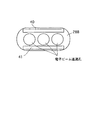
図1は、カラー受像管1の構成を示す水平走査方向への断面図である。
【0021】
この図に示すように、前記カラー受像管1は、多数の電子ビーム通過孔の形成されたシャドウマスク11と対向するように、R(赤色)、G(緑色)、B(青色)3色の蛍光体が裏面に各層状に塗布されたスクリーン12を備えた受像管10と、前記受像管10のネック部13の基端側より挿入されたインライン型電子銃20とから構成されている。そして、インライン型電子銃20より放出されたRGB各色に対応した3本の電子ビーム30R、30G、30Bそれぞれはネック部13とファンネル部の拡径部14との境界面その表面に沿って設けられた偏向コイル15によって惹起される偏向磁界の中を通過して垂直・水平方向に所定量偏向されスクリーン12上の所定の位置に焦点される。
【0022】
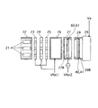
上記インライン型電子銃20の構造の詳細について説明する。
図2は、前記インライン型電子銃20の斜視図であり、図3は、内部構成をより詳細に示す上面図である。
この図に示すように、インライン型電子銃20は、3組のインライン配置された陰極21と、これを収納する格子電極22と、加速電極23と、集束電極24と、集束電極25と、集束電極26と、集束電極27と、最終加速電極28と、シールドカップ29とからなる。各電極には電子ビームの生成・加速・集束を行うための電界を形成させる電圧が、電極間に所定の電位差を生じさせるように所定量印加される。そして、3本の電子ビームが径の大きさ・その軌道を制御されながら所定の方向へと射出される。
【0023】
詳しくは、陰極21から電子ビームが生み出され、陰極21、格子電極22及び加速電極23によって、電子ビームのエネルギー量(電流量)を制御する。次いで、加速電極23と集束電極24との間にプリフォーカスレンズ電界が生成され、後の主レンズ電界に入射する電子ビームの発散角を調整している。集束電極24、25、26はユニポテンシャル型であり、前記プリフォーカスレンズ電界による電子ビームの予備集束を補助する作用を果たしている。
【0024】
集束電極27と最終加速電極28とで以下に述べるように主レンズ電界を構成し、係る主レンズ電界で発散角を最終調整されたものが偏向コイルによって生成されている偏向磁界に向かって射出されることになる。
集束電極27と最終加速電極28は、それぞれ3本の電子ビームを、取り囲む水平走査方向に長い扁平な筒状をなした筒状外周電極27A、筒状外周電極28Aと、筒状外周電極27A及び筒状外周電極28Aの対向端面から後退させた位置に、電子ビームがほぼ垂直に通過するように配置された3つの孔27B1、27B2、27B3が開口された補正電極板27B、電子ビームがほぼ垂直に通過するように配置された3つの孔28B1、28B2、28B3が開口された補正電極板28Bからなる。この集束電極27と最終加速電極28は、電子銃の主レンズ電界を生成する役割を担うものである。
【0025】
このように主レンズ電界を形成する集束電極27と最終加速電極28の筒状外周電極27A及び筒状外周電極28Aの内部に配置された補正電極板27B、補正電極板28Bを内方に後退させることによって、集束電極27内部に最終加速電極28の高電位(図中Va)が深く侵入され、かつ、最終加速電極28内部に集束電極27の低電位(図中Vfoc2)が深く侵入させられることになる。また、特に最終加速電極に関しては、内部にこの補正電極板を有していることにより、補正電極板を有さない場合に比べて、外周電極28Aの集束電極側端部に近い位置に3つ孔が配置されることになる。このため、内部に補正電極板を有さない場合に比べて、3つの電子ビーム通過孔が作る3つのレンズにおいてセンターレンズとサイドレンズとのピッチが大となる(逆に、補正電極板を有さない場合は、3つの電子ビーム通過孔は、シールドカップに形成されたものだけからなり、外周電極28Aの集束電極側端部から遠くに位置することになるため、外周電極内で3つのレンズの径が大きくなりレンズ中心が近寄ることでピッチが小さくなる)。このようにセンターレンズとサイドレンズとのピッチが大きくなると、その分、シャドウマスクとスクリーンとの距離を短くすることができ、これにより、地磁気によるビームずれ移動を生じにくくすることができる、という利点もある。
【0026】
上記構成において、集束電極24及び集束電極26には電位Vfoc1が印加され、集束電極27にはダイナミック電圧Vfoc2が印加される。Vfoc1は固定的であり、Vfoc2は電子ビームの偏向量に応じて増加され、両者の関係は偏向量がゼロ(偏向されない)の場合には、Vfoc1>Vfoc2に設定されてある。これにより、主レンズ電界による作用を偏向量が増すに連れて弱めることによって、非点収差を補正しビームスポット形状を制御することが可能となる。そして、更に、このようにダイナミック電圧をVfoc1>Vfoc2の状態から制御することにより、ダイナミック電圧の低減を図ることが可能となる。なお、この方法については特許第3040272号公報に詳しく記載されているところである。
【0027】
以下に補正電極板28Bの構成図を図4に示す。この図に示すように補正電極板28Bは、外周電極28Aの開口形状と相似形状の水平走査方向に長い扁平な板体に3つの円状の孔が設けられたものである。
そして、この補正電極板には電極40、41が衝立状に導電可能に取着されている(この電極を衝立状電極板と呼ぶ)。この衝立状電極板40、41は、図2及び図3に示すように、水平走査方向に互いに平行に伸び電子ビーム通過孔を挟み込むように配置されている。また、集束電極27及び最終加速電極28との対向部分に形成されたギャップGap側に突き出すように、このギャップ側に面する面側に設けられる。
【0028】
このように衝立状電極板がギャップ側に突き出すように配置されることで、主レンズにおいて、水平方向と垂直方向での集束力の差(これをHV差と称する)を拡大させることができ、これにより、ダイナミック電圧の値を低減させることができる。ここにおいて、ダイナミック電圧を印加することにより、HV差が拡大しレンズ作用が弱まる。主レンズを構成する電界やスポットの歪みを直接的に感度良く改善できるという作用効果も有する。
【0029】
ここで、図6は、衝立状電極板40、41を設けない場合の主レンズ電界によるレンズモデルを示す図であり、この中で(a)は水平断面(水平走査方向)を(b)に垂直断面(垂直走査方向)のレンズモデルを示す。
この図に示すように、主レンズは、水平方向と垂直方向で集束力が異なり、前述のとおり、この集束力の差つまりHV差を大きく設定することがダイナミック電圧を低減させる上で重要となる。
【0030】
このレンズモデルでは、60、61、62が主レンズ電界による主レンズであり、水平方向では集束作用の強い凸レンズであり、垂直方向ではこれよりも集束作用の弱い凸レンズを構成している(レンズ作用の強弱はレンズの厚みで図示してある)。そして、スクリーン上に焦点させるには、かかる水平及び垂直方向で生じるレンズ作用の差を補うように主レンズの陰極側、つまり、電子ビームの速度が比較的遅い電子ビーム位置にレンズ63、64、65を別途形成する。このレンズは、水平方向では発散作用の強い凹レンズを、垂直方向では集束作用の強い凸レンズを構成する4極レンズである。
【0031】
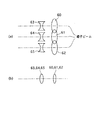
図5は、衝立状電極板40、41を設けた本実施形態の場合の主レンズ電界によるレンズモデルを示す図であり、この中で(a)は水平断面(水平走査方向)を(b)に垂直断面(垂直走査方向)のレンズモデルを示す。
この図に示すように、衝立状電極板により補助レンズが付加されており、このものも主レンズとして機能していると考えられる。
【0032】
具体的には、このレンズモデルでは、50、51、52が主レンズ電界による主レンズの一つであり、水平方向では集束作用の強い凸レンズであり、垂直方向では集束作用を有する凸レンズを構成している。そして、更に、レンズ50、51、52に加えて衝立状電極板の付加による補助レンズ53、54、55が付加形成されている。このレンズは、水平方向では集束作用の強い凸レンズであり、垂直方向では発散作用を有する凹レンズを構成する4極レンズである。そして、スクリーン上に焦点させるには、かかる水平及び垂直方向で生じるレンズ作用の差を補うように主レンズの陰極側、つまり、電子ビームの速度が比較的遅い位置で、水平方向では発散作用の強い凹レンズを、垂直方向では集束作用の強い凸レンズを構成する4極レンズ56、57、58が形成される。
【0033】
以上のことから明らかなように、本実施形態のように衝立状電極板を設けることによって、補助レンズが付加されたぶんHV差が増大されることになる。その結果、従来のもの(衝立状電極板のないもの)と比べてダイナミック電圧を低減させることができる。
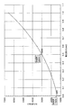
ここで、補正電極板に衝立状電極板を設けることによりHV差が増大されることについて具体例を挙げる。図7に、補正電極板からの衝立状電極板の高さの変化に対するHV差(ここでは、水平方向フォーカス電圧と垂直方向フォーカス電圧の差を示す)の変化を示す。衝立状電極の高さが0.0のとき、つまり従来技術のように補正電極板があって衝立状電極板がない場合のHV差は1400Vであるのに対して、衝立状電極板を取り付けてその高さを高くしていくほど、HV差が高くなる。
【0034】
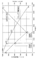
図8は、HV差を変化させたときの、ダイナミック電圧の変化と、水平スポット径の変化を示す図である。HV差を高くすると、ダイナミック電圧を低減することができ、その分の耐圧強度を低くできるため回路の簡素化やコスト低減が期待できる。しかし、HV差を変化させると水平スポット径も変化し、水平スポット径は、HV差を高くすると一旦小さくなるもののあるHV差付近からまた大きくなってしまうので、この水平スポット径が最小になる付近のHV差とすることが望ましい。本実施の形態で挙げた電子銃では、HV差が3000V付近で水平スポット径が最も小さい。
【0035】
このことにより、本実施の形態では、HV差を3000Vとするよう、衝立状電極の高さを0.5mm程度としている(図7参照)。このようにすることにより、ダイナミック電圧、水平スポット径ともに、従来技術より小さい値とすることができる。なお、参考までに他の部分の寸法を挙げると、本実施の形態の電子銃において、衝立状電極が設けられた補正電極板を有する筒状電極の管軸方向長さは7.0mm、そのスクリーン側端部から補正電極板までの管軸方向長さは4.6mm、補正電極板の厚みは0.7mmである。
【0036】
なお、衝立状電極板40、41は、上記のように集束電極27及び最終加速電極28との対向部分に形成されたギャップ側に突き出すように、このギャップ側に面する面側に設けることで、上記補助レンズによるレンズ作用が最大限に生かされることになる。つまり、衝立状電極板の先端を電位勾配の急峻な前記ギャップに近い位置に設けることで、レンズ電界に対する感度を高められる。ただし、あまり近づけ過ぎると、厚みの薄い板材が低圧側に近接することになる結果、近接部分で放電が発生するなどの好ましくない現象が生じるので、その位置はかかる放電が生じない程度に制限される必要はある。なお、衝立状電極板の高さは高いほど先端がギャップに近づくのでダイナミック電圧を低減する効果は向上するが、本発明のように筒状部の内部に設けた補正電極板に衝立状電極板を設ける構成とすれば、衝立状電極板自体の高さを高くしなくとも先端をギャップに近づけることができるので、衝立状電極板の取り付け精度が高く維持され、その結果、衝立状電極板の先端の開き度合いのばらつきに起因した作用のばらつきを回避できるという利点もある。
【0037】
また、スクリーン側の4極レンズ53、54、55と、陰極側の4極レンズ56、57、58の二重四極子の効果により水平方向のレンズ倍率を小さく、垂直方向のレンズ倍率を大きくすることができるという効果も奏することから、非点収差が更に補正され電子ビームスポットが横長に歪むという問題を更に抑制することができる。
【0038】
なお、電子銃を以下の構成とすることもできる。図9は、この変形例のインライン型電子銃の構成を示す平面図である。
この図に示すように、変形例では、上記のインライン型電子銃において集束電極27と最終加速電極28との間に中間電極70を備えている。ここには、抵抗R1を介して電位Vm2が印加される。このような構成により、上記した作用・効果に加えて電界レンズが管軸方向に拡張されるため、実効的なレンズ口径を更に大きくすることが可能となる。なお、かかる構成・効果等については特開平8−22780号公報に詳しい。
【0039】
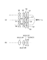
[実施形態2]
次に、本発明の第二の実施形態について説明する。
図10は、本実施形態に係るインライン型電子銃の構成を示す平面図であり、図11にそのレンズモデルを示した。
実施形態1との相違点は、補正電極板27Bにも、一対の衝立状電極板60、61が上記同様に、集束電極27及び最終加速電極28との対向部分に形成されたギャップ側に突き出すように、このギャップ側に面する面側に設けてある。
【0040】
かかるに構成により、図11に示すような図5のレンズに加えて主レンズよりも低圧側に水平方向で発散作用(凹レンズ)、垂直方向で集束作用(凸レンズ)を有する4極レンズ66,67、68が生成される。
このレンズにより、主レンズの球面収差の影響が大きな低圧部において水平方向の集束力が弱まるため、スポット特性に最も影響する水平方向の球面収差を弱めることが可能となる。
【0041】
また、陰極側の4極レンズ56、57、58の強さは、電極27と28との間での電位差により決まり、レンズ作用を強めようとすれば放電等の問題を生じることから電位差を大きくするには制限があるため、陰極側の4極レンズ56、57、58の強さにはおのずと限界がある。しかし、前記主レンズ低圧側のレンズ66、67、68が補助的に陰極側の4極レンズ56、57、58を強める働きをするため、かかる制限を受けることなく、HV差をより大きくすることができる(二重4極子の効果を高める)。
【0042】
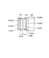
[実施形態3]
次に、本発明の第三の実施形態について説明する。
図12は、本実施形態に係るインライン型電子銃の構成を示す平面図である。この図に示すように本インライン型電子銃では、実施形態1のインライン型電子銃において、シールドカップに凸部29Aを形成しこの部分を最終加速電極内に突入させ、その底部29Bが前記補正電極板として機能させる構成としてある。
つまり、電子ビームがほぼ垂直に通過するように配置された前記補正電極に設けたのと同じ3つの孔を底部29Bに形成したシールドカップを筒状外周電極内部の中ほどまでその底部29Bが位置するように挿入させてある。そして、その底部29Bに上記同様に衝立状電極板40、41を設けてある。
【0043】
このような構成により、上記した作用・効果を奏するとともに、シールドカップを筒状部に嵌め込むと同時にその内部へ補正電極を配置することができるので、電子銃の組立を容易に行うことができる。
なお、実施形態2、3は各単独で実施することもできるが、それらを相互に組み合わせるとしても良い。これにより相乗的な効果が得られる。
【0044】
また、上記説明のように、本発明では、ダイナミック電圧を印加する技術に特に有効であるが、これに限ったものではない。電極にダイナミック電圧を印加しない電子銃においても、HV差の調整手段として適用することは可能である。
【0045】
【発明の効果】
以上説明してきたとおり、本発明のカラー受像管装置によれば、衝立状電極板を設けるという設計上困難性を伴わない手法によって、従来の主レンズ系に加えて衝立状電極板の付加による補助レンズを付加形成して、主レンズにおいて水平方向と垂直方向での集束力の差を拡大させて、その結果、ダイナミック電圧をよりいっそう低減させることが可能となる。
【図面の簡単な説明】
【図1】実施形態に共通なカラー受像管の構成を示す水平走査方向への断面図である。
【図2】実施形態1のインライン型電子銃の構成を示す斜視図である。
【図3】図2のインライン型電子銃の構成を示す平面図である。
【図4】補正電極板及び衝立状電極板の構成を示す正面図及び側面図である。
【図5】実施形態1のインライン型電子銃における主たるレンズ構成を示すモデル図である。
【図6】従来例(衝立状電極板がない場合)のインライン型電子銃における主たるレンズ構成を示すモデル図である。
【図7】補正電極板からの衝立状電極板の高さの変化に対するHV差(ここでは、水平方向フォーカス電圧と垂直方向フォーカス電圧の差を示す)の変化を示す図である。
【図8】 HV差を変化させたときの、ダイナミック電圧の変化と、水平スポット径の変化を示す図である。
【図9】実施形態1のインライン型電子銃の変形例の構成を示す平面図である。
【図10】実施形態2のインライン型電子銃の構成を示す平面図である。
【図11】実施形態2のインライン型電子銃における主たるレンズ構成を示すモデル図である。
【図12】実施形態3のインライン型電子銃の構成を示す平面図である。
【図13】従来のインライン型電子銃(OLFレンズ構成)の構成を示す平面図である。
【符号の説明】
20 インライン型電子銃
27 集束電極
27A 筒状外周電極
27B 補正電極板
28 最終加速電極
28A 筒状外周電極
28B 補正電極板
29 シールドカップ
29A 凸部(シールドカップ部分)
29B 底部(シールドカップ部分)
40、41,60、61 衝立状電極板
50〜58 主レンズ(4極レンズ)
53〜55 補助レンズ(主レンズを構成)
66〜68 4極レンズ(衝立状電極板60、61によって発生)
70 中間電極[0001]
BACKGROUND OF THE INVENTION
The present invention relates to a color picture tube device, and more particularly to an electrode constituting a main lens for focusing a plurality of electron beams on a screen.
[0002]
[Prior art]
In general, a color picture tube apparatus has an envelope made up of a panel and a funnel integrally joined to the panel, and three electron beams emitted from an electron gun arranged in the neck of the funnel are A color image is displayed by being deflected by the horizontal and vertical deflection magnetic fields generated by the deflection device mounted on the outside and being emitted onto a phosphor screen formed facing the shadow mask on the inner surface of the panel while performing horizontal and vertical scanning. It is formed as follows.
[0003]
In general, the magnetic field of the deflecting device used in such a color picture tube device has a self-convergence configuration in which three electron beams are concentrated on the screen. The deflection magnetic field is distorted in a barrel shape. For this reason, the three electron beams that pass through the deflection magnetic field receive a diverging action in the horizontal direction and a focusing action in the vertical direction.
[0004]
When the electron beam trajectory becomes longer as the deflection angle increases, the above-mentioned astigmatism appears remarkably in the periphery of the phosphor screen surface due to the self-convergence magnetic field as described above, and the electron beam spot becomes longer in the horizontal direction. There is a problem that the horizontal resolution is reduced due to a horizontally long and flat cross-sectional shape on which the axis is placed. This problem has become more prominent due to the flattening of panels and the expansion of the deflection angle as in recent years.
[0005]
Therefore, in order to draw an image with high resolution on the phosphor screen surface, it is necessary to reduce the spot diameter in the horizontal direction in advance by a child gun.
As one attempt to meet this demand, a technique for applying a dynamic voltage to a focusing electrode constituting an electron gun is known. In this method, a voltage that increases as the amount of deflection increases is applied to the focusing electrode that is positioned closest to the final electrode. As a result, the action of the main lens electric field increases as the amount of deflection increases. It is a technique for correcting the beam spot shape by correcting astigmatism.
[0006]
As an application of such dynamic voltage technology, the shape and direction of the beam passage hole of the electrode are adjusted so that the applied dynamic voltage can be reduced, and the condition of the voltage applied to each electrode is specified. A technique is proposed in Japanese Patent No. 3040272.
By the way, the spot diameter in the color picture tube device can be made smaller as the spherical aberration in the main lens electric field of the electron gun is smaller. When the incident angle of the electron beam to the main lens electric field is α, the spot diameter δ contributed by the most dominant spherical aberration in the main lens electric field is
δ = (M ・ CsP ・ α Three ) / 2
It is expressed. Here, M is a lens magnification, and CsP is a spherical aberration coefficient. As can be seen from this equation, spherical aberration is reduced when the lens action by the main lens electric field is weakened. That is, the spot diameter on the phosphor screen can be reduced by effectively increasing the lens diameter by the main lens electric field.
[0007]
The OLF disclosed in Japanese Examined Patent Publication No. 2-18540 as realizing this concept by the electrode structure ( O ver L apping F ield) there is a lens. The electrode configuration is shown in FIG.
As shown in FIG. 13, the main electrode includes a focusing
[0008]
The focusing
[0009]
The focusing
[0010]
[Patent Document 1]
Patent No. 3040272
[0011]
[Patent Document 2]
No. 2-18540
[0012]
[Patent Document 3]
JP-A-8-22780
[0013]
[Problems to be solved by the invention]
Here, when the dynamic voltage technology is applied to the electrode configuration constituting the OLF lens and the dynamic voltage is to be reduced to a low value, the voltage value to be applied to the electrode by adjusting the shape and direction of the beam passage hole is set. According to the specified method, it is difficult to make the beam passage hole optimally designed to satisfy all the characteristics, and there is a limit in design and the feasibility is poor.
[0014]
An object of the present invention is to provide a color picture tube provided with an electron gun that can easily reduce the dynamic voltage when an OLF lens is combined with a dynamic voltage technique.
[0015]
[Means for Solving the Problems]
In order to achieve the above object, the present invention provides a panel having a screen formed of phosphors of a plurality of colors, a plurality of cathode portions arranged in-line, and a plurality of particles emitted from the cathode portion and directed toward the screen. An electron gun having an electron gun having a cylindrical electrode that is arranged on a path of an electron beam through a gap and has a flat cylindrical shape that is long in the horizontal scanning direction, and the cylindrical electrode includes: An aperture common to the plurality of electron beams, a correction electrode plate provided so that one principal surface faces the gap at a position retracted from an end provided with the aperture, and the correction electrode plate A plurality of beam passage holes provided to form a main lens electric field, and the correction electrode plate of at least one cylindrical electrode sandwiches the beam passage hole from the vertical direction in the horizontal direction and the Wherein a pair of partition-like electrode plate extending in a direction towards the gap lens field is formed is provided.
[0016]
According to this, an auxiliary lens is formed by adding a screen-like electrode plate in addition to the conventional lens system by a method without design difficulties, including a correction electrode plate and providing a screen-like electrode plate. With this auxiliary lens, the difference in the focusing force between the horizontal direction and the vertical direction in the main lens is enlarged, and as a result, the dynamic voltage can be further reduced.
[0017]
Here, the cylindrical electrode having the correction electrode provided with the screen-like electrode includes a final electrode on the screen side.
By providing the correction electrode plate and the screen electrode plate in the final electrode in this way, an auxiliary lens is formed on the most screen side in the electron gun, and the focusing power in the horizontal and vertical directions of the main lens is adjusted efficiently. Can be planned.
[0018]
Here, when the number of the cylindrical electrodes having the correction electrode provided with the screen-like electrode is two or more, other than the final electrode includes a focusing electrode located on the cathode side of the final electrode, To do.
Thereby, it becomes possible to weaken spherical aberration and improve the effect of the double quadrupole lens.
[0019]
Here, the bottom of the shield cup provided on the screen side of the final electrode protrudes into the final electrode, so that the bottom functions as the correction electrode plate.
In this way, the shield electrode can be fitted into the cylindrical portion, and at the same time, the correction electrode can be disposed therein, so that the electron gun can be easily assembled.
[0020]
DETAILED DESCRIPTION OF THE INVENTION
[Embodiment 1]
Hereinafter, a
FIG. 1 is a cross-sectional view in the horizontal scanning direction showing the configuration of the
[0021]
As shown in this figure, the
[0022]
Details of the structure of the in-
FIG. 2 is a perspective view of the inline-
As shown in this figure, the in-line
[0023]
Specifically, an electron beam is generated from the
[0024]
The focusing
The focusing
[0025]
In this way, the focusing
[0026]
In the above configuration, the potential Vfoc1 is applied to the focusing
[0027]
A configuration diagram of the
[0028]
By arranging the partition-like electrode plate so as to protrude to the gap side in this way, in the main lens, the difference in the focusing force between the horizontal direction and the vertical direction (referred to as HV difference) can be enlarged, Thereby, the value of the dynamic voltage can be reduced. Here, by applying a dynamic voltage, the HV difference is enlarged and the lens action is weakened. There is also an effect that the electric field and spot distortion constituting the main lens can be directly improved with high sensitivity.
[0029]
Here, FIG. 6 is a diagram showing a lens model based on a main lens electric field when the screen-
As shown in this figure, the main lens has different focusing powers in the horizontal direction and the vertical direction. As described above, it is important to set the difference in focusing power, that is, the HV difference, to reduce the dynamic voltage. .
[0030]
In this lens model, 60, 61, and 62 are main lenses based on a main lens electric field, which are convex lenses having a strong focusing action in the horizontal direction and forming a convex lens having a weaker focusing action in the vertical direction (lens action). Is shown by the lens thickness). In order to focus on the screen, the
[0031]
FIG. 5 is a diagram showing a lens model based on a main lens electric field in the case of this embodiment provided with the screen-
As shown in this figure, an auxiliary lens is added by a screen-like electrode plate, which is considered to function as a main lens.
[0032]
Specifically, in this lens model, 50, 51, and 52 are one of the main lenses based on the main lens electric field, and constitute a convex lens having a strong focusing action in the horizontal direction and a convex lens having a focusing action in the vertical direction. ing. Further, in addition to the
[0033]
As is apparent from the above, by providing the screen-like electrode plate as in the present embodiment, the HV difference is increased by adding the auxiliary lens. As a result, the dynamic voltage can be reduced as compared with the conventional one (without the screen electrode plate).
Here, a specific example will be given of the fact that the HV difference is increased by providing the partition electrode plate on the correction electrode plate. FIG. 7 shows changes in the HV difference (here, the difference between the horizontal direction focus voltage and the vertical direction focus voltage) with respect to the change in the height of the screen electrode plate from the correction electrode plate. When the height of the screen electrode is 0.0, that is, when there is a correction electrode plate and no screen electrode plate as in the prior art, the HV difference is 1400V, but the screen electrode plate is attached. The higher the height, the higher the HV difference.
[0034]
FIG. 8 is a diagram showing a change in dynamic voltage and a change in horizontal spot diameter when the HV difference is changed. If the HV difference is increased, the dynamic voltage can be reduced and the withstand voltage strength can be lowered accordingly, so that simplification of the circuit and cost reduction can be expected. However, if the HV difference is changed, the horizontal spot diameter will also change, and if the HV difference is increased, the horizontal spot diameter will increase once again from the vicinity of the HV difference, but this horizontal spot diameter will be minimized. It is desirable to make HV difference. In the electron gun mentioned in this embodiment, the horizontal spot diameter is the smallest when the HV difference is around 3000V.
[0035]
Thus, in the present embodiment, the height of the screen-like electrode is set to about 0.5 mm so that the HV difference is 3000 V (see FIG. 7). By doing so, both the dynamic voltage and the horizontal spot diameter can be set to values smaller than those of the prior art. For reference, the dimensions of other parts are as follows. In the electron gun of the present embodiment, the length of the cylindrical electrode having the correction electrode plate provided with the screen-like electrode is 7.0 mm. The length in the tube axis direction from the screen side end to the correction electrode plate is 4.6 mm, and the thickness of the correction electrode plate is 0.7 mm.
[0036]
The screen-
[0037]
In addition, the lens magnification in the horizontal direction is reduced and the lens magnification in the vertical direction is increased by the double quadrupole effect of the screen
[0038]
The electron gun can be configured as follows. FIG. 9 is a plan view showing a configuration of an inline type electron gun of this modification.
As shown in this figure, in the modification, an
[0039]
[Embodiment 2]
Next, a second embodiment of the present invention will be described.
FIG. 10 is a plan view showing the configuration of the inline-type electron gun according to the present embodiment, and FIG. 11 shows the lens model thereof.
The difference from the first embodiment is that a pair of screen-
[0040]
With this configuration, in addition to the lens of FIG. 5 as shown in FIG. 11,
With this lens, since the horizontal focusing force is weakened in the low-pressure portion where the influence of the spherical aberration of the main lens is large, it is possible to weaken the horizontal spherical aberration that most affects the spot characteristics.
[0041]
Further, the strength of the cathode-
[0042]
[Embodiment 3]
Next, a third embodiment of the present invention will be described.
FIG. 12 is a plan view showing the configuration of the inline-type electron gun according to the present embodiment. As shown in this figure, in this inline type electron gun, in the inline type electron gun of
That is, the bottom 29B is positioned to the middle of the cylindrical outer peripheral electrode of the shield cup in which the same three holes as those provided in the correction electrode arranged so that the electron beam passes substantially vertically are formed in the bottom 29B. It is inserted to do. In the bottom 29B, screen-
[0043]
With such a configuration, the above-described operations and effects can be achieved, and the correction electrode can be disposed inside the shield cup while being fitted into the cylindrical portion. Therefore, the electron gun can be easily assembled. .
In addition, although Embodiment 2 and 3 can also be implemented each independently, it is good also as combining them mutually. This provides a synergistic effect.
[0044]
Further, as described above, the present invention is particularly effective for a technique for applying a dynamic voltage, but is not limited thereto. Even an electron gun that does not apply a dynamic voltage to the electrodes can be applied as a means for adjusting the HV difference.
[0045]
【The invention's effect】
As described above, according to the color picture tube apparatus of the present invention, it is possible to provide assistance by adding a screen-like electrode plate in addition to the conventional main lens system by a method without design difficulty of providing a screen-like electrode plate. By additionally forming a lens, the difference in focusing force between the horizontal direction and the vertical direction in the main lens can be enlarged, and as a result, the dynamic voltage can be further reduced.
[Brief description of the drawings]
FIG. 1 is a cross-sectional view in the horizontal scanning direction showing a configuration of a color picture tube common to an embodiment.
FIG. 2 is a perspective view illustrating a configuration of an inline-type electron gun according to the first embodiment.
3 is a plan view showing a configuration of the inline-type electron gun of FIG. 2;
FIGS. 4A and 4B are a front view and a side view showing a configuration of a correction electrode plate and a screen-like electrode plate, respectively.
FIG. 5 is a model diagram illustrating a main lens configuration in the inline-type electron gun according to the first embodiment.
FIG. 6 is a model diagram showing a main lens configuration in an in-line type electron gun of a conventional example (when there is no screen-like electrode plate).
FIG. 7 is a diagram illustrating a change in HV difference (here, a difference between a horizontal focus voltage and a vertical focus voltage) with respect to a change in the height of a screen electrode plate from a correction electrode plate.
FIG. 8 is a diagram showing a change in dynamic voltage and a change in horizontal spot diameter when the HV difference is changed.
9 is a plan view showing a configuration of a modified example of the inline-type electron gun of
FIG. 10 is a plan view showing a configuration of an inline-type electron gun according to a second embodiment.
FIG. 11 is a model diagram illustrating a main lens configuration in an inline-type electron gun according to a second embodiment.
12 is a plan view showing a configuration of an inline-type electron gun according to Embodiment 3. FIG.
FIG. 13 is a plan view showing a configuration of a conventional in-line type electron gun (OLF lens configuration).
[Explanation of symbols]
20 In-line type electron gun
27 Focusing electrode
27A Cylindrical outer peripheral electrode
27B Correction electrode plate
28 Final acceleration electrode
28A Cylindrical outer peripheral electrode
28B Correction electrode plate
29 Shield Cup
29A Convex (shield cup part)
29B Bottom (shield cup part)
40, 41, 60, 61 Screen electrode plate
50-58 Main lens (4-pole lens)
53-55 Auxiliary lens (composed of main lens)
66-68 quadrupole lens (generated by
70 Intermediate electrode
Claims (4)
前記筒状電極は、前記複数の電子ビームに共通な開孔と、前記開孔の設けられた端部から後退した位置に一主面が前記ギャップに対向するように備えられた補正電極板と、前記補正電極板に設けられた複数のビーム通過孔を有し、主レンズ電界を形成し、
少なくとも一つの前記筒状電極の前記補正電極板には、前記ビーム通過孔を垂直方向から挟み込む状態で、水平方向及び前記主レンズ電界が形成されるギャップに向かう方向に伸びる一対の衝立状電極板が設けられている
ことを特徴とするカラー受像管装置。A panel having a screen formed of phosphors of a plurality of colors, a plurality of cathode portions arranged in-line, and a plurality of electron beams emitted from the cathode portion and traveling toward the screen side, arranged with a gap therebetween. A color picture tube device comprising an electron gun having a cylindrical electrode having a flat cylindrical shape that is long in the horizontal scanning direction ,
The cylindrical electrode includes an aperture common to the plurality of electron beams, and a correction electrode plate provided so that one principal surface faces the gap at a position retracted from an end portion where the aperture is provided. , Having a plurality of beam passage holes provided in the correction electrode plate, forming a main lens electric field,
The correction electrode plate of at least one of the cylindrical electrodes has a pair of screen-like electrode plates extending in a horizontal direction and a direction toward the gap where the main lens electric field is formed with the beam passage hole being sandwiched from the vertical direction. A color picture tube device characterized by comprising:
ことを特徴とする請求項1に記載のカラー受像管装置。2. The color picture tube apparatus according to claim 1, wherein the cylindrical electrode including the correction electrode provided with the screen-like electrode includes a final electrode on a screen side. 3.
ことを特徴とする請求項2に記載のカラー受像管装置。The focusing electrode located on the cathode side of the final electrode other than the final electrode is included when the number of the cylindrical electrodes having the correction electrode provided with the screen-shaped electrode is two or more. 2. A color picture tube apparatus according to 2.
ことを特徴とする請求項2又は3に記載のカラー受像管装置。4. The bottom portion functions as the correction electrode plate by forming a bottom surface of a shield cup provided on the screen side of the final electrode so as to protrude into the final electrode. A color picture tube device according to claim 1.
Priority Applications (1)
| Application Number | Priority Date | Filing Date | Title |
|---|---|---|---|
| JP2003019295A JP4189227B2 (en) | 2002-03-20 | 2003-01-28 | Color picture tube device |
Applications Claiming Priority (3)
| Application Number | Priority Date | Filing Date | Title |
|---|---|---|---|
| JP2002077853 | 2002-03-20 | ||
| JP2002-77853 | 2002-03-20 | ||
| JP2003019295A JP4189227B2 (en) | 2002-03-20 | 2003-01-28 | Color picture tube device |
Publications (2)
| Publication Number | Publication Date |
|---|---|
| JP2003346682A JP2003346682A (en) | 2003-12-05 |
| JP4189227B2 true JP4189227B2 (en) | 2008-12-03 |
Family
ID=29781912
Family Applications (1)
| Application Number | Title | Priority Date | Filing Date |
|---|---|---|---|
| JP2003019295A Expired - Fee Related JP4189227B2 (en) | 2002-03-20 | 2003-01-28 | Color picture tube device |
Country Status (1)
| Country | Link |
|---|---|
| JP (1) | JP4189227B2 (en) |
-
2003
- 2003-01-28 JP JP2003019295A patent/JP4189227B2/en not_active Expired - Fee Related
Also Published As
| Publication number | Publication date |
|---|---|
| JP2003346682A (en) | 2003-12-05 |
Similar Documents
| Publication | Publication Date | Title |
|---|---|---|
| JP3576217B2 (en) | Picture tube device | |
| JPH0831333A (en) | Color cathode ray tube | |
| JPH07134953A (en) | Color picture tube | |
| JPH0393135A (en) | Color picture tube | |
| JPH03205744A (en) | Shadow mask type color picture tube | |
| US6339284B1 (en) | Color cathode ray tube apparatus having auxiliary grid electrodes | |
| KR100201762B1 (en) | Color cathode ray tube with enhanced focus | |
| JPH0395835A (en) | Color picture tube device | |
| JP4189227B2 (en) | Color picture tube device | |
| US6927531B2 (en) | Electron gun and color picture tube apparatus that attain a high degree of resolution over the entire screen | |
| US6337534B1 (en) | Color cathode ray tube with coma reduced | |
| JPH08148095A (en) | Electron gun and color cathode ray tube equipped with this electron gun | |
| JPH05135709A (en) | Cathode ray tube | |
| EP1349193B1 (en) | Color picture tube apparatus | |
| US6570314B2 (en) | Color display tube | |
| JP2690913B2 (en) | Color picture tube | |
| JP3074176B2 (en) | Electron gun for cathode ray tube | |
| JPH08106862A (en) | Color picture tube | |
| JPH07262935A (en) | Cathode ray tube and electron gun | |
| JP3588248B2 (en) | Color picture tube equipment | |
| US7030548B2 (en) | Cathode-ray tube apparatus | |
| JP3050386B2 (en) | Electron gun for color picture tube | |
| JP3050385B2 (en) | Electron gun for color picture tube | |
| KR100646910B1 (en) | Cathode ray tube apparatus | |
| US6515438B2 (en) | Electron gun in color CRT |
Legal Events
| Date | Code | Title | Description |
|---|---|---|---|
| A621 | Written request for application examination |
Free format text: JAPANESE INTERMEDIATE CODE: A621 Effective date: 20050909 |
|
| A131 | Notification of reasons for refusal |
Free format text: JAPANESE INTERMEDIATE CODE: A131 Effective date: 20080603 |
|
| A521 | Written amendment |
Free format text: JAPANESE INTERMEDIATE CODE: A523 Effective date: 20080804 |
|
| TRDD | Decision of grant or rejection written | ||
| A01 | Written decision to grant a patent or to grant a registration (utility model) |
Free format text: JAPANESE INTERMEDIATE CODE: A01 Effective date: 20080819 |
|
| A01 | Written decision to grant a patent or to grant a registration (utility model) |
Free format text: JAPANESE INTERMEDIATE CODE: A01 |
|
| A61 | First payment of annual fees (during grant procedure) |
Free format text: JAPANESE INTERMEDIATE CODE: A61 Effective date: 20080912 |
|
| R150 | Certificate of patent or registration of utility model |
Free format text: JAPANESE INTERMEDIATE CODE: R150 |
|
| FPAY | Renewal fee payment (event date is renewal date of database) |
Free format text: PAYMENT UNTIL: 20110919 Year of fee payment: 3 |
|
| LAPS | Cancellation because of no payment of annual fees |