JP4190247B2 - Hollow resin container - Google Patents
Hollow resin container Download PDFInfo
- Publication number
- JP4190247B2 JP4190247B2 JP2002292018A JP2002292018A JP4190247B2 JP 4190247 B2 JP4190247 B2 JP 4190247B2 JP 2002292018 A JP2002292018 A JP 2002292018A JP 2002292018 A JP2002292018 A JP 2002292018A JP 4190247 B2 JP4190247 B2 JP 4190247B2
- Authority
- JP
- Japan
- Prior art keywords
- resin container
- hollow resin
- deformation
- container
- hollow
- Prior art date
- Legal status (The legal status is an assumption and is not a legal conclusion. Google has not performed a legal analysis and makes no representation as to the accuracy of the status listed.)
- Expired - Fee Related
Links
Images





Landscapes
- Containers Having Bodies Formed In One Piece (AREA)
Description
【0001】
【発明の属する技術分野】
本発明は、ブロー成形によって形成される中空樹脂容器に関し、特に容器の内圧の変化による変形を吸収するようにした中空樹脂容器に関する。
【0002】
【従来の技術】
清涼飲料水等の飲料品の他、液体状或いは粉粒体状の食品、洗浄剤、薬品等、各種の内容物を収容する容器として、例えば樹脂ボトル容器等の中空樹脂容器が多用されている。このような中空樹脂容器としては、その強度や成形性、収容される内容物の物性等に応じて、種々の形状、大きさ、硬さ等を備える容器が選択使用されることになる。
【0003】
清涼飲料水等の飲料品を収容する中空樹脂容器としては、二軸延伸ブロー成形により形成されたポリエチレンテレフタレート(PET)製の樹脂容器が用いられるのが一般的である。また、このようなPET製の樹脂容器は、例えば高温加熱殺菌を必要とする内容物を収容する場合、高温加熱された内容物の充填後や、充填した内容物の加熱中に、加熱又は冷却による熱変形を生じやすい。このような熱変形を吸収して容器の外観が損なわれないようにした中空樹脂容器が知られており(例えば、特許文献1参照)、この特許文献1に記載の樹脂容器によれば、容器の胴部の各側壁には、内圧の変化を吸収するためのパネル壁がそれぞれ設けられており、このパネル壁は、側壁の平坦部分を矩形状に凹溝で囲んで形成され、且つ矩形の中心に設けた船底状の底稜線の両端からV字状に矩形状凹溝の隅部に達する一対の傾斜稜線を形成して、圧力変形可能な窪み壁としたものである。
【0004】
【特許文献1】
特開平8−276924号公報(第2−3頁、図1、図2、図7)
【0005】
【発明が解決使用とする課題】
特許文献1に記載の圧力変形可能な窪み壁を設けた樹脂容器によれば、二軸延伸ブロー成形により形成されたPET製の中空容器であって、樹脂弾性率が例えば3000MPa程度の樹脂から得られる硬い材質の中空容器であるため、上述のように配置されたパネル壁によって、加熱又は冷却による内圧の変化に伴う変形を効果的に吸収することが可能である。
【0006】
しかしながら、例えば液体洗剤、柔軟剤、食用油等を収容するための樹脂容器であって、樹脂弾性率が200〜1500MPa程度の樹脂として例えばポリエチレン(PE)を用いた軟らかい材質の中空樹脂容器の場合、加熱又は冷却による内圧の変化の他、例えば内容物の酸化等の化学変化による加圧や減圧が生じて圧力変形が大きくなると、当該パネル壁によって充分に変形を吸収することができなくなり、パネル壁の変形が外観形状に現れる程度に大きくなると共に、パネル壁以外の部分にも変形が生じて外観形状を保持できなくなるおそれがある。
【0007】
本発明は、特に樹脂弾性率が200〜1500MPaの樹脂を用いて形成した樹脂容器においても、内圧の変化に伴う変形を効果的に吸収して、外観形状を容易に保持することのできる中空樹脂容器を提供することを目的とする。
【0008】
【課題を解決するための手段】
本発明は、ブロー成形によって形成される中空樹脂容器であって、容器の内圧の変化による変形を吸収する変形吸収パネル部をその胴部に備えており、該変形吸収パネル部は、略寄棟屋根形状の凸部又は凹部を複数連接配置して構成されている中空樹脂容器を提供することにより、上記目的を達成したものである。
【0009】
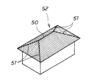
本願において、略寄棟屋根形状は、図6に示すような、大棟50の両端に四つの隅棟51が会する形式の屋根である寄棟屋根52と略同様の形状又はこれと類似の形状を意味するものである。また、略寄棟屋根形状の各稜線は、直線状の他、円弧状に湾曲する形状であっても良く、各稜線による山又は谷の先端は、R形状に面取りされたものであっても良い。
【0010】
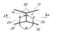
そして、本発明の中空樹脂容器によれば、略寄棟屋根形状の凸部又は凹部を正面から視た場合の隣接する一対の隅棟稜線間の角度α(図3参照)が120度以上、大棟稜線と隅棟稜線間の角度β(図3参照)が120度以下となっており、従ってα≧βとなっていることが好ましい。一対の隅棟稜線間の角度αが120度以上、大棟稜線と隅棟稜線間の角度βが120度以下であることにより、内圧の変化に伴う変形を一部に集中させることなく均等に分散させて効果的に吸収することが可能になる。
【0011】
また、本発明の中空樹脂容器によれば、略寄棟屋根形状の凸部又は凹部の大棟稜線と垂直な方向の断面A−A(図3参照)に沿った両側の傾斜面の接合角度γ(図4参照)が90度以上となっていることが好ましい。大棟稜線を挟んだ両側の傾斜面の接合角度γが90度以上であることにより、内圧の変化に伴う変形を一部に集中させることなく均等に分散させて効果的に吸収することが可能になる。
【0012】
【発明の実施の形態】
図1及び図2に示す本発明の好ましい一実施形態に係る中空樹脂容器10は、曲げ弾性率(JIS K 7106)、片持ちばりによるプラスチックの曲げこわさ試験法に従って測定された樹脂弾性率が200〜1500MPaの熱可塑性樹脂として、例えば中密度ポリエチレンを用いてダイレクトブロー成形により得られた直径50〜90mm程度の円形断面を有するボトル状の樹脂容器である。また本実施形態の中空樹脂容器10は、例えば200〜700cc程度の容量を有し、内容物として、例えば環境変化や経時変化によってガスを発生する性質を有する漂白剤等や、酸素を吸収する性質を有する食用油等が収容され、封止された容器10の内部に加圧や減圧を生じさせることになる。
【0013】
そして、本実施形態の中空樹脂容器10によれば、容器10の内圧の変化による変形を吸収する変形吸収パネル部11をその胴部12に備えており、変形吸収パネル部11は、略寄棟屋根形状の凹部13を複数連接配置して構成されている。
【0014】
また、本実施形態によれば、中空樹脂容器10は、先端ノスル部15、肩部16、胴部12、底部17、及び上げ底部を一体として備えており、また胴部12は、シュリンクラベルが取り付けられるラベル部18と、ラベル上方部19及びラベル下方部20とからなっている。なお、本実施形態によれば、中空樹脂容器10は、先端ノズル部15の肉厚が例えば1.5mm、肩部16の肉厚が例えば1.0mm、ラベル上方部19の肉厚が例えば0.8mm、ラベル部18の肉厚が例えば0.5mm、ラベル下方部20の肉厚が例えば0.8mm、底部17の肉厚が例えば1.0mm、上げ底部の肉厚が例えば1.5mmとなるようにダイレクトブロー成形によって形成されている。また、先端ノスル部15には、キャップが装着されて容器10の内部に内容物を封入することができるようになっている。
【0015】
本実施形態によれば、変形吸収パネル部11は、略寄棟屋根形状の凹部13を、大棟稜線14が平行となるように胴部12の周方向に複数連接配置して、当該胴部12の周方向全周にわたってリング状に連続して設けられている。また、変形吸収パネル部11は、ラベル密着リブ21をリング状に介在させつつ、大棟稜線14を互い違いに配置した状態で上下方向に7段設けられていることにより、胴部12の略70%の領域を占めるように配設されることになる。なお、変形吸収パネル部11は、好ましくは胴部12の30〜100%の領域を占めるように設けられることにより、内圧の変化に伴う変形を一部に集中させることなく均等に分散させて効果的に吸収ことが可能になる。
【0016】
本実施形態によれば、周方向に連接配置されて各変形吸収パネル部11を構成する略寄棟屋根形状の凹部13は、大棟稜線14の両端に各二つの隅棟稜線22が各々会している、寄棟屋根を表裏逆さにした形状と略同様の形状を有するもので、図3に拡大して示すように、その正面から視た形状が、例えば5〜10mm程度の長さの大棟稜線14の両端から7〜15mm程度の長さの隅棟稜線22が各々Y字形に延設する形状となっている。また隣接する一対の隅棟稜線22間の角度αが例えば140〜160度、大棟綾線14と隅棟稜線22との間の角度βが例えば100〜110度となっており、従ってα≧βとなっている。なお、これらの各稜線14,22間の角度α,βは、これらの各稜線14,22が例えば弧状に湾曲するものである場合には、当該弧状の線の両端を結んだ直線間の角度を意味するものである。
【0017】
また、本実施形態によれば、略寄棟屋根形状の凹部13を大棟稜線14と垂直な断面A−Aで切った際における、図4に示すような両側の傾斜面23の接合角度γが例えば90〜100度となっており、各凹部13の深さDは例えば3〜5mmとなっている。なお、傾斜面23の接合角度γは、当該傾斜面23が湾曲面である場合には、断面A−Aで切った当該湾曲面の断面線の両端を結んだ直線間の角度を意味するものである。また凹部13の深さは、当該凹部13の両側の隣接する凹部13との接合部からの深さを意味するものである。
【0018】
そして、本実施形態の中空樹脂容器10によれば、内圧の変化に伴う変形を効果的に吸収して、容器10の外観形状を容易に保持することができる。すなわち、本実施形態によれば、中空樹脂容器10は、その胴部12に、略寄棟屋根形状の凹部13を複数連接配置してなる変形吸収パネル部11を備えているので、収容した内容物の化学変化等によって封止された容器10の内部に加圧や減圧を生じても、この圧力による応力を凹部13に集中させることにより、当該凹部13において局所的に変形を吸収させて、中空樹脂容器10の全体の外観形状に現れるような変形を効果的に回避することが可能になる。また、各変形吸収パネル部11に略寄棟屋根形状の凹部13が複数連接して配置されているので、圧力による応力を複数の凹部13に効率良く分散させて、さらに効果的に中空樹脂容器10の全体の変形を回避することが可能になる。
【0019】
したがって、本実施形態の中空樹脂容器10によれば、例えばラベル部18にシュリンクラベルをラベル密着リブ21に密着させて取り付けた場合において、封止された容器10の内部に加圧や減圧が生じても、これらの圧力による変形を凹部13において局所的に吸収して、ラベル密着リブ21に変形を生じさせないので、シュリンクラベルをラベル密着リブ21に密着させた状態を容易に保持して、その外観形状に影響が及ぶのを効果的に回避することが可能になる。
【0020】
なお、本発明は上記実施形態に限定されることなく種々の変更が可能である。例えば、上下方向に複数段設けられる変形吸収パネル部11は、図5に示すように、大棟稜線14の位置を互い違いにすることなく一致させて設けることもでき、また複数段設ける必要は必ずしもない。また変形吸収パネル部を周方向全周に連続させてリング状に設ける必要は必ずしもなく、凹部に代えて、略寄棟屋根形状の凸部を連接して変形吸収パネル部を構成しても良い。さらに、本発明の中空樹脂容器は、円形断面を有するものに限定されることなく、例えば三角形、四角形等の多角形断面を有するものであっても良く、多角形断面の各面に、上下又は左右に連接する略寄棟屋根形状の凸部又は凹部を設けて本発明の中空樹脂容器とすることもできる。さらにまた、本発明は、樹脂弾性率が200〜1500MPaの熱可塑性樹脂からなる中空樹脂容器に限定されることなく、例えば樹脂弾性率が3000MPa程度のPET製の中空容器等に適用することもできる。
【0021】
【実施例】
以下、実施例及び比較例により、本発明の中空樹脂容器をさらに詳細に説明するが、本発明はこれらに限定されるものではない。
【0022】
〔実施例1,2〕
図1及び図2に示す上記実施形態の中空樹脂容器10と同様の構成を有する容器を実施例1の中空樹脂容器とし、図5に示す大棟稜線を一致させた容器を実施例2の中空樹脂容器として、有限要素法による解析によって内部の加圧や減圧による加圧変形量を、各容器の胴部12におけるラベル密着リブ21の直径の変化として解析した。なお、加圧前の各容器のラベル密着リブ21の直径は74.0mmだった。また、加圧による内圧の変化を+0.01MPa、減圧による内圧の変化を−0.01MPaとした。解析結果を図7(a),(b)に示す。
【0023】
〔比較例1〕
変形吸収パネル部を全く設けることなく、胴部を滑らかな円筒形状としたこと以外は図1及び図2に示す中空樹脂容器10と同様の構成を有する容器を比較例1の中空樹脂容器として、後述する有限要素法による解析によって内部の加圧や減圧による加圧変形量を、胴部の直径の変化として解析した。なお、加圧前の胴部の直径は74.0mmだった。また、加圧による内圧の変化を+0.01MPa、減圧による内圧の変化を−0.01MPaとした。解析結果を図7(a),(b)に示す。
【0024】
図7(a),(b)に示す評価結果によれば、本発明に係る実施例1及び実施例2の中空樹脂容器は、内圧の変化に伴う変形を効果的に吸収することができ、外観形状を保持する機能に優れていることが判明する。
【0025】
【発明の効果】
本発明の中空樹脂容器によれば、特に樹脂弾性率が200〜1500MPaの樹脂を用いて形成した樹脂容器においても、内圧の変化に伴う変形を効果的に吸収して、外観形状を容易に保持することができる。
【図面の簡単な説明】
【図1】本発明の一実施形態に係る中空樹脂容器を示す斜視図である。
【図2】本発明の一実施形態に係る中空樹脂容器を示す正面図である。
【図3】略寄棟屋根形状の凹部を拡大して示す正面図である。
【図4】略寄棟屋根形状の凹部の図3のA−Aに沿った断面図である。
【図5】本発明の中空樹脂容器の他の形態を例示する斜視図である。
【図6】寄棟屋根の説明図である。
【図7】(a)及び(b)は、内部の加圧や減圧による加圧変形量の解析結果を示すチャートである。
【符号の説明】
10 中空樹脂容器
11 変形吸収パネル部
12 胴部
13 略寄棟屋根形状の凹部
14 大棟稜線
18 ラベル部
19 ラベル上方部
20 ラベル下方部
21 ラベル密着リブ
22 隅棟稜線
23 大棟稜線の両側の傾斜面[0001]
BACKGROUND OF THE INVENTION
The present invention relates to a hollow resin container formed by blow molding, and more particularly to a hollow resin container adapted to absorb deformation due to a change in internal pressure of the container.
[0002]
[Prior art]
In addition to beverages such as soft drinks, hollow resin containers such as resin bottle containers are often used as containers for storing various contents such as liquid or granular foods, cleaning agents, and medicines. . As such a hollow resin container, a container having various shapes, sizes, hardnesses, and the like is selectively used depending on its strength, moldability, physical properties of the contents to be stored, and the like.
[0003]
As a hollow resin container for containing beverages such as soft drinks, a resin container made of polyethylene terephthalate (PET) formed by biaxial stretch blow molding is generally used. Further, such a PET resin container, for example, when containing contents that require high-temperature heat sterilization, is heated or cooled after filling the high-temperature heated contents or during the heating of the filled contents. It tends to cause thermal deformation. A hollow resin container that absorbs such thermal deformation so that the appearance of the container is not impaired is known (for example, see Patent Document 1). According to the resin container described in Patent Document 1, the container Each side wall of the body portion is provided with a panel wall for absorbing a change in internal pressure. The panel wall is formed by surrounding a flat portion of the side wall with a rectangular groove and having a rectangular shape. A pair of inclined ridge lines that reach the corners of the rectangular concave groove in a V shape from both ends of a ship bottom-shaped bottom ridge line provided at the center are formed as pressure-deformable hollow walls.
[0004]
[Patent Document 1]
JP-A-8-276924 (page 2-3, FIG. 1, FIG. 2, FIG. 7)
[0005]
[Problems to be Solved by the Invention]
According to the resin container provided with the pressure deformable hollow wall described in Patent Document 1, it is a PET hollow container formed by biaxial stretch blow molding, and obtained from a resin having a resin elastic modulus of, for example, about 3000 MPa. Since the hollow container is made of a hard material, the panel wall arranged as described above can effectively absorb the deformation accompanying the change in internal pressure due to heating or cooling.
[0006]
However, for example, a resin container for containing a liquid detergent, softener, edible oil, etc., and a hollow resin container made of a soft material using, for example, polyethylene (PE) as a resin having a resin elastic modulus of about 200 to 1500 MPa In addition to changes in internal pressure due to heating or cooling, when pressure deformation due to chemical changes such as oxidation of contents occurs and pressure deformation increases, the panel wall cannot absorb the deformation sufficiently, and the panel While the deformation of the wall increases to the extent that it appears in the external shape, the external shape may not be maintained due to the deformation occurring in portions other than the panel wall.
[0007]
The present invention is a hollow resin that can effectively retain the external shape by effectively absorbing the deformation accompanying the change of the internal pressure even in a resin container formed using a resin having a resin elastic modulus of 200 to 1500 MPa. The purpose is to provide a container.
[0008]
[Means for Solving the Problems]
The present invention is a hollow resin container formed by blow molding, and is provided with a deformation absorption panel portion that absorbs deformation due to a change in the internal pressure of the container, and the deformation absorption panel portion is substantially a dormitory. The object is achieved by providing a hollow resin container configured by connecting a plurality of roof-shaped convex portions or concave portions.
[0009]
In the present application, the substantially dormitory roof shape is substantially the same as or similar to the
[0010]
And according to the hollow resin container of the present invention, the angle α (see FIG. 3) between a pair of adjacent corner ridges when the convex part or concave part of the substantially laid roof shape is viewed from the front is 120 degrees or more, The angle β (see FIG. 3) between the large ridge line and the corner ridge line is 120 degrees or less, and therefore it is preferable that α ≧ β. The angle α between the pair of corner ridge lines is 120 degrees or more, and the angle β between the large ridge ridge line and the corner ridge lines is 120 degrees or less, so that deformation due to changes in internal pressure is evenly concentrated without partial concentration. It can be dispersed and effectively absorbed.
[0011]
Moreover, according to the hollow resin container of this invention, the joining angle of the inclined surface of both sides along the cross section AA (refer FIG. 3) of the direction perpendicular | vertical to the large ridgeline of the convex part of a dormitory roof shape, or a recessed part It is preferable that γ (see FIG. 4) is 90 degrees or more. The joint angle γ between the inclined surfaces on both sides of the main building ridgeline is 90 degrees or more, so that the deformation accompanying the change of internal pressure can be evenly distributed and absorbed effectively without concentrating on a part. become.
[0012]
DETAILED DESCRIPTION OF THE INVENTION
The
[0013]
And according to the
[0014]
Moreover, according to this embodiment, the
[0015]
According to the present embodiment, the deformation absorbing panel unit 11 includes a plurality of concavity roof-
[0016]
According to the present embodiment, the
[0017]
In addition, according to the present embodiment, the joint angle γ of the
[0018]
And according to the
[0019]
Therefore, according to the
[0020]
The present invention is not limited to the above-described embodiment, and various modifications can be made. For example, as shown in FIG. 5, the deformation absorbing panel portion 11 provided in a plurality of stages in the vertical direction can be provided with the positions of the
[0021]
【Example】
Hereinafter, the hollow resin container of the present invention will be described in more detail with reference to Examples and Comparative Examples, but the present invention is not limited thereto.
[0022]
Examples 1 and 2
The container having the same configuration as the
[0023]
[Comparative Example 1]
A container having the same configuration as that of the
[0024]
According to the evaluation results shown in FIGS. 7 (a) and (b), the hollow resin containers of Example 1 and Example 2 according to the present invention can effectively absorb deformation accompanying changes in internal pressure, It turns out that it is excellent in the function of maintaining the appearance shape.
[0025]
【The invention's effect】
According to the hollow resin container of the present invention, even in a resin container formed using a resin having a resin modulus of 200 to 1500 MPa, the external shape can be easily retained by effectively absorbing the deformation accompanying the change in internal pressure. can do.
[Brief description of the drawings]
FIG. 1 is a perspective view showing a hollow resin container according to an embodiment of the present invention.
FIG. 2 is a front view showing a hollow resin container according to an embodiment of the present invention.
FIG. 3 is an enlarged front view showing a substantially ridge roof-shaped recess.
4 is a cross-sectional view taken along line AA of FIG.
FIG. 5 is a perspective view illustrating another embodiment of the hollow resin container of the present invention.
FIG. 6 is an explanatory diagram of a dormitory roof.
FIGS. 7A and 7B are charts showing analysis results of pressure deformation due to internal pressurization and decompression.
[Explanation of symbols]
DESCRIPTION OF
Claims (5)
容器の内圧の変化による変形を吸収する変形吸収パネル部をその胴部に備えており、
該変形吸収パネル部は、略寄棟屋根形状の凸部又は凹部を複数連接配置して構成されている中空樹脂容器。A hollow resin container formed by blow molding,
The body is equipped with a deformation absorption panel that absorbs deformation due to changes in the internal pressure of the container,
The deformation absorbing panel portion is a hollow resin container configured by connecting a plurality of substantially ridged roof-shaped convex portions or concave portions.
Priority Applications (1)
| Application Number | Priority Date | Filing Date | Title |
|---|---|---|---|
| JP2002292018A JP4190247B2 (en) | 2002-10-04 | 2002-10-04 | Hollow resin container |
Applications Claiming Priority (1)
| Application Number | Priority Date | Filing Date | Title |
|---|---|---|---|
| JP2002292018A JP4190247B2 (en) | 2002-10-04 | 2002-10-04 | Hollow resin container |
Publications (2)
| Publication Number | Publication Date |
|---|---|
| JP2004123197A JP2004123197A (en) | 2004-04-22 |
| JP4190247B2 true JP4190247B2 (en) | 2008-12-03 |
Family
ID=32283401
Family Applications (1)
| Application Number | Title | Priority Date | Filing Date |
|---|---|---|---|
| JP2002292018A Expired - Fee Related JP4190247B2 (en) | 2002-10-04 | 2002-10-04 | Hollow resin container |
Country Status (1)
| Country | Link |
|---|---|
| JP (1) | JP4190247B2 (en) |
Families Citing this family (2)
| Publication number | Priority date | Publication date | Assignee | Title |
|---|---|---|---|---|
| JP2007030893A (en) * | 2005-07-22 | 2007-02-08 | Yoshino Kogyosho Co Ltd | Synthetic resin bottle |
| JP6169406B2 (en) * | 2013-04-30 | 2017-07-26 | 株式会社吉野工業所 | Hot filling bottle |
-
2002
- 2002-10-04 JP JP2002292018A patent/JP4190247B2/en not_active Expired - Fee Related
Also Published As
| Publication number | Publication date |
|---|---|
| JP2004123197A (en) | 2004-04-22 |
Similar Documents
| Publication | Publication Date | Title |
|---|---|---|
| CN101511686B (en) | Channel features for pressurized bottle | |
| RU2340521C2 (en) | Plastic bottle | |
| WO2000051894A1 (en) | Synthetic resin thin wall container | |
| US20060207962A1 (en) | Bottle with reinforced top portion | |
| JP4148439B2 (en) | Plastic bottle | |
| AU2006267001B2 (en) | Synthetic resin bottle body | |
| JP4190247B2 (en) | Hollow resin container | |
| EP3511257A1 (en) | Synthetic resin bottle | |
| TWI355356B (en) | ||
| JP4130166B2 (en) | Shrink label mounting container | |
| JPH0776333A (en) | Plastic bottle | |
| JPH0656138A (en) | Plastic bottle | |
| JPH07101442A (en) | Plastic bottle | |
| JP7170465B2 (en) | Gusseted bags and bag-in-box | |
| JP4876604B2 (en) | container | |
| JP4998768B2 (en) | Synthetic resin square housing | |
| JPH08276924A (en) | Square hollow container made of synthetic resin | |
| JP4936247B2 (en) | Synthetic resin square housing | |
| JP2004323100A (en) | Synthetic resin-made bottle container equipped with depressurization absorption wall | |
| JP2004149126A (en) | Square container made of synthetic resin | |
| JP5177389B2 (en) | Pinch grip type bottle container | |
| JP2008037505A (en) | Wide mouth PET container with handle | |
| JP6584108B2 (en) | Plastic container | |
| JP3805572B2 (en) | Easy to crush plastic bottle | |
| JP2009007061A (en) | Synthetic resin made container with label |
Legal Events
| Date | Code | Title | Description |
|---|---|---|---|
| A621 | Written request for application examination |
Free format text: JAPANESE INTERMEDIATE CODE: A621 Effective date: 20050823 |
|
| A977 | Report on retrieval |
Free format text: JAPANESE INTERMEDIATE CODE: A971007 Effective date: 20080709 |
|
| A131 | Notification of reasons for refusal |
Free format text: JAPANESE INTERMEDIATE CODE: A131 Effective date: 20080805 |
|
| A521 | Written amendment |
Free format text: JAPANESE INTERMEDIATE CODE: A523 Effective date: 20080821 |
|
| TRDD | Decision of grant or rejection written | ||
| A01 | Written decision to grant a patent or to grant a registration (utility model) |
Free format text: JAPANESE INTERMEDIATE CODE: A01 Effective date: 20080916 |
|
| A01 | Written decision to grant a patent or to grant a registration (utility model) |
Free format text: JAPANESE INTERMEDIATE CODE: A01 |
|
| A61 | First payment of annual fees (during grant procedure) |
Free format text: JAPANESE INTERMEDIATE CODE: A61 Effective date: 20080916 |
|
| FPAY | Renewal fee payment (event date is renewal date of database) |
Free format text: PAYMENT UNTIL: 20110926 Year of fee payment: 3 |
|
| R151 | Written notification of patent or utility model registration |
Ref document number: 4190247 Country of ref document: JP Free format text: JAPANESE INTERMEDIATE CODE: R151 |
|
| FPAY | Renewal fee payment (event date is renewal date of database) |
Free format text: PAYMENT UNTIL: 20120926 Year of fee payment: 4 |
|
| R250 | Receipt of annual fees |
Free format text: JAPANESE INTERMEDIATE CODE: R250 |
|
| FPAY | Renewal fee payment (event date is renewal date of database) |
Free format text: PAYMENT UNTIL: 20130926 Year of fee payment: 5 |
|
| R250 | Receipt of annual fees |
Free format text: JAPANESE INTERMEDIATE CODE: R250 |
|
| R250 | Receipt of annual fees |
Free format text: JAPANESE INTERMEDIATE CODE: R250 |
|
| R250 | Receipt of annual fees |
Free format text: JAPANESE INTERMEDIATE CODE: R250 |
|
| R250 | Receipt of annual fees |
Free format text: JAPANESE INTERMEDIATE CODE: R250 |
|
| R250 | Receipt of annual fees |
Free format text: JAPANESE INTERMEDIATE CODE: R250 |
|
| R250 | Receipt of annual fees |
Free format text: JAPANESE INTERMEDIATE CODE: R250 |
|
| R250 | Receipt of annual fees |
Free format text: JAPANESE INTERMEDIATE CODE: R250 |
|
| R250 | Receipt of annual fees |
Free format text: JAPANESE INTERMEDIATE CODE: R250 |
|
| LAPS | Cancellation because of no payment of annual fees |