JP4196331B2 - Airbag device - Google Patents
Airbag device Download PDFInfo
- Publication number
- JP4196331B2 JP4196331B2 JP2003137695A JP2003137695A JP4196331B2 JP 4196331 B2 JP4196331 B2 JP 4196331B2 JP 2003137695 A JP2003137695 A JP 2003137695A JP 2003137695 A JP2003137695 A JP 2003137695A JP 4196331 B2 JP4196331 B2 JP 4196331B2
- Authority
- JP
- Japan
- Prior art keywords
- airbag
- return
- vehicle
- retracted state
- deployed
- Prior art date
- Legal status (The legal status is an assumption and is not a legal conclusion. Google has not performed a legal analysis and makes no representation as to the accuracy of the status listed.)
- Expired - Fee Related
Links
Images



Landscapes
- Air Bags (AREA)
Description
【0001】
【発明の属する技術分野】
本発明は、車両のエアバッグ装置に関する。
【0002】
【従来の技術】
障害物に対する車両の衝突等から乗員を保護する技術としては種々のものが提案されている。その代表的なものとしては、車両の衝突時に車室内で展開されるエアバッグが挙げられる。また、車両と障害物との衝突を事前に予知し、乗員の保護を図る技術も提案されている。例えば、特許文献1には車両と障害物とが予知された場合に、シートベルトを巻き取ってシートに対する乗員の拘束力を高めることで、車室内における乗員の怪我を防止する技術が提案されている。
【0003】
一方、衝突時の車両の安全性を高める技術としては、乗員のみならず障害物若しくは車両自体の保護を図る技術も提案されている。例えば、特許文献2には障害物と車両との衝突が予知された場合、車両外部でエアバッグを展開することで万一衝突した場合における障害物の保護を図る技術が提案されている。このような技術は障害物の保護の重要性から着目されつつある技術である。
【0004】
【特許文献1】
特開2000−142321号公報
【特許文献2】
特開平6−239198号公報
【0005】
【発明が解決しようとする課題】
ここで、障害物や車両自体の保護を十分に図るため、実際に衝突が生じるか否かは別としてその危険性があれば衝突が予知されることが望ましく、より早期にエアバッグを展開して保護性能を高めるためには、衝突予知の感度は高い方が望ましい。しかし、衝突予知の感度を高くすれば衝突の誤予知も頻発し、それだけエアバッグを展開する頻度も高くなる。この点、一旦エアバッグを展開すれば、これを元の格納状態に復帰させる必要があるが、従来のエアバッグ装置は使用頻度が多数回に及ぶことが想定されていない。また、展開されたエアバッグを元の格納状態に復帰する際には、復帰中のエアバッグに異物等が巻き込まれることはないかといったように周囲の安全性を確認できることが望ましい。
【0006】
従って、本発明の主たる目的は、障害物及び車両自体の保護を図る上で、頻発的な衝突予知に対応し得ると共に、周囲の安全性を確認しつつ、展開されたエアバッグを格納状態に復帰することができるエアバッグ装置を提供することにある。
【0009】
【課題を解決するための手段】
本発明によれば、車両の外部前方で展開可能に格納されたエアバッグと、格納状態にある前記エアバッグを繰り返し展開可能であって、障害物との衝突が予知された場合に前記エアバッグを展開する展開手段と、操作者による操作を受けつける操作手段と、前記操作手段に対する操作があった場合に、展開された前記エアバッグを格納状態に復帰させる復帰手段と、を備え、前記復帰手段は、一旦前記操作手段に対する操作があれば、格納完了まで、展開された前記エアバッグの復帰動作を継続することを特徴とするエアバッグ装置が提供される。
本発明のエアバッグ装置によれば、前記展開手段と前記復帰手段とを設けたことで、エアバッグを反復して使用することが可能となる。従って、障害物及び車両自体の保護を図る上で、衝突の誤予知が頻発してもこれに対応することができる。また、本発明は、前記操作手段に対して操作があった場合にエアバッグを格納状態に復帰させるので、乗員等の操作者は周囲の安全性を確認した上でエアバッグを格納状態に復帰させることを指示することができ、エアバッグ復帰時の安全性をより向上できる。また、操作者は一旦前記操作手段に対して操作をすれば、その後に操作を要求されることなく、操作者はエアバッグの格納状態への復帰を注視することができ、安全性を向上できる。
【0010】
また、本発明によれば、車両の外部前方で展開可能に格納されたエアバッグと、格納状態にある前記エアバッグを繰り返し展開可能であって、障害物との衝突が予知された場合に前記エアバッグを展開する展開手段と、操作者による操作を受けつける操作手段と、前記操作手段に対する操作があった場合に、展開された前記エアバッグを格納状態に復帰させる復帰手段と、を備え、前記復帰手段は、前記操作手段に対する操作があった場合、その後の前記操作手段に対する操作に応じて、展開された前記エアバッグの復帰動作を中止することを特徴とするエアバッグ装置が提供される。
本発明のエアバッグ装置によれば、前記展開手段と前記復帰手段とを設けたことで、エアバッグを反復して使用することが可能となる。従って、障害物及び車両自体の保護を図る上で、衝突の誤予知が頻発してもこれに対応することができる。また、本発明は、前記操作手段に対して操作があった場合にエアバッグを格納状態に復帰させるので、乗員等の操作者は周囲の安全性を確認した上でエアバッグを格納状態に復帰させることを指示することができ、エアバッグ復帰時の安全性をより向上できる。また、例えば、エアバッグの復帰中に異物等が巻き込まれたことが確認された場合、前記操作手段に対する操作によりエアバッグの復帰動作を中止することができ、エアバッグ復帰時の安全性をより向上することができる。
【0011】
また、本発明によれば、車両の外部前方で展開可能に格納されたエアバッグと、格納状態にある前記エアバッグを繰り返し展開可能であって、障害物との衝突が予知された場合に前記エアバッグを展開する展開手段と、操作者による操作を受けつける操作手段と、前記操作手段に対する操作があった場合に、展開された前記エアバッグを格納状態に復帰させる復帰手段と、を備え、前記復帰手段は、前記操作手段に対する操作があった後、予め定めた時間の経過後に、展開された前記エアバッグを格納状態に復帰させることを特徴とするエアバッグ装置が提供される。
本発明のエアバッグ装置によれば、前記展開手段と前記復帰手段とを設けたことで、エアバッグを反復して使用することが可能となる。従って、障害物及び車両自体の保護を図る上で、衝突の誤予知が頻発してもこれに対応することができる。また、本発明は、前記操作手段に対して操作があった場合にエアバッグを格納状態に復帰させるので、乗員等の操作者は周囲の安全性を確認した上でエアバッグを格納状態に復帰させることを指示することができ、エアバッグ復帰時の安全性をより向上できる。また、操作者には前記操作手段に対する操作後、エアバッグの周囲の安全性を確認する時間が与えられ、エアバッグ復帰時の安全性をより向上することができる。
【0012】
また、本発明によれば、車両の外部前方で展開可能に格納されたエアバッグと、格納状態にある前記エアバッグを繰り返し展開可能であって、障害物との衝突が予知された場合に前記エアバッグを展開する展開手段と、操作者による操作を受けつける操作手段と、前記操作手段に対する操作があった場合に、展開された前記エアバッグを格納状態に復帰させる復帰手段と、を備え、前記操作手段は、操作者が両手でなければ同時に操作できないように設けられた複数の操作部を備え、前記復帰手段は当該複数の操作部が同時に操作された場合に展開された前記エアバッグを格納状態に復帰させることを特徴とするエアバッグ装置が提供される。
本発明のエアバッグ装置によれば、前記展開手段と前記復帰手段とを設けたことで、エアバッグを反復して使用することが可能となる。従って、障害物及び車両自体の保護を図る上で、衝突の誤予知が頻発してもこれに対応することができる。また、本発明は、前記操作手段に対して操作があった場合にエアバッグを格納状態に復帰させるので、乗員等の操作者は周囲の安全性を確認した上でエアバッグを格納状態に復帰させることを指示することができ、エアバッグ復帰時の安全性をより向上できる。また、操作者は両手を使わなければエアバッグの復帰が行えないので、例えば、乗員が前記操作手段に対する操作を行い、エアバッグを格納状態に復帰させながら車両を運転する等、不適切な行為を防止することができる。
【0015】
また、本発明によれば、車両の外部前方で展開可能に格納されたエアバッグと、格納状態にある前記エアバッグを繰り返し展開可能であって、障害物との衝突が予知された場合に前記エアバッグを展開する展開手段と、操作者による操作を受けつける操作手段と、前記操作手段に対する操作があった場合に、展開された前記エアバッグを格納状態に復帰させる復帰手段と、前記エアバッグが展開された場合に、当該エアバッグを格納状態へ復帰する方法を案内する案内情報を出力する出力手段と、を備えたことを特徴とするエアバッグ装置が提供される。
本発明のエアバッグ装置によれば、前記展開手段と前記復帰手段とを設けたことで、エアバッグを反復して使用することが可能となる。従って、障害物及び車両自体の保護を図る上で、衝突の誤予知が頻発してもこれに対応することができる。また、本発明は、前記操作手段に対して操作があった場合にエアバッグを格納状態に復帰させるので、乗員等の操作者は周囲の安全性を確認した上でエアバッグを格納状態に復帰させることを指示することができ、エアバッグ復帰時の安全性をより向上できる。また、エアバッグの復帰手順が案内されるので、操作者は誤ることなくエアバッグを格納状態に復帰させることができる。
【0016】
この場合、前記出力手段が、前記案内情報を表示するタッチパネルであり、前記操作手段は、前記案内情報と共に前記タッチパネル上に表示される操作ボタンであってもよい。こうすることで、エアバッグの復帰に必要な場合のみ前記操作手段が前記操作ボタンとして現れるようになり、前記操作手段を常設する必要がなくなる。
【0017】
また、本発明によれば、車両の外部前方で展開可能に格納されたエアバッグと、格納状態にある前記エアバッグを繰り返し展開可能であって、障害物との衝突が予知された場合に前記エアバッグを展開する展開手段と、操作者による操作を受けつける操作手段と、前記操作手段に対する操作があった場合に、展開された前記エアバッグを格納状態に復帰させる復帰手段と、前記エアバッグが格納状態にない場合に、前記車両の制御部に対して、前記車両の走行禁止指示を出力する出力手段と、を備えたことを特徴とするエアバッグ装置が提供される。
本発明のエアバッグ装置によれば、前記展開手段と前記復帰手段とを設けたことで、エアバッグを反復して使用することが可能となる。従って、障害物及び車両自体の保護を図る上で、衝突の誤予知が頻発してもこれに対応することができる。また、本発明は、前記操作手段に対して操作があった場合にエアバッグを格納状態に復帰させるので、乗員等の操作者は周囲の安全性を確認した上でエアバッグを格納状態に復帰させることを指示することができ、エアバッグ復帰時の安全性をより向上できる。また、エアバッグが展開等された状態のまま車両が走行することが防止され、車両走行時の安全性をより向上することができる。
【0018】
また、本発明によれば、車両の外部前方で展開可能に格納されたエアバッグと、格納状態にある前記エアバッグを繰り返し展開可能であって、障害物との衝突が予知された場合に前記エアバッグを展開する展開手段と、操作者による操作を受けつける操作手段と、前記操作手段に対する操作があった場合に、展開された前記エアバッグを格納状態に復帰させる復帰手段と、前記車両の走行時に、前記復帰手段による前記エアバッグの格納状態への復帰を規制する規制手段と、を設けたことを特徴とするエアバッグ装置が提供される。
本発明のエアバッグ装置によれば、前記展開手段と前記復帰手段とを設けたことで、エアバッグを反復して使用することが可能となる。従って、障害物及び車両自体の保護を図る上で、衝突の誤予知が頻発してもこれに対応することができる。また、本発明は、前記操作手段に対して操作があった場合にエアバッグを格納状態に復帰させるので、乗員等の操作者は周囲の安全性を確認した上でエアバッグを格納状態に復帰させることを指示することができ、エアバッグ復帰時の安全性をより向上できる。また、車両走行時の風圧や路面との干渉等の要因により、エアバッグが格納状態に復帰できないという状況を防止することが可能となる。
【0023】
【発明の実施の形態】
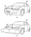
以下、本発明の好適な実施の形態について図面を参照して説明する。図1は本発明の一実施形態に係るエアバッグ装置を適用した車両の外観図であり、(a)はエアバッグの格納状態を、(b)はエアバッグの展開状態を示している。本実施形態の場合、図1(a)に示すように車両の前方、特にバンパー中央部に、角筒形状をした、エアバッグ1の格納部2を設けており、通常時エアバッグ1はこの格納部2内に折り畳まれた状態で格納されている。なお、この格納部2の前方に開閉可能な扉体を設けて、エアバッグ1の格納時にエアバッグ1が外部に露出しないようにこの扉体で格納部2の開口を閉鎖するようにしてもよい。
【0024】
図1(a)の態様で車両が走行中、衝突予知センサ108により車両の前方に存在する障害物との衝突が予知されると、エアバッグ1が図1(b)に示すように車両の前方で展開する。これにより障害物が直接車体と接触することが防止され、障害物及び車両自体の保護を図ることができる。なお、本実施形態では展開時のエアバッグ1の形状を車幅方向に延びた棒状としているが種々の形状、大きさを採用可能である。
【0025】
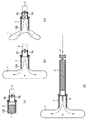
図2(a)乃至(c)はエアバッグ1の展開及び格納状態への復帰を行うブロア・バキューム装置の動作説明図である。格納部2の前端部内側には内圧センサ109が設けられている。この内圧センサ109はエアバッグ1の展開時にエアバッグ1内の気圧を検出するためのセンサであり、本実施形態では車両と障害物との衝突の検出に用いる。すなわち、エアバッグ1が展開し、これに障害物が衝突した場合にはエアバッグ1内の気圧が通常よりも上昇するため、この気圧を検出することで障害物との衝突の判定が可能となる。なお、障害物との衝突を検出するためには、このような内圧センサ109に代えて、例えば、エアバッグ1の表面に圧力センサを設け、この圧力センサに障害物が接触することを利用して衝突判定をするように構成することも可能である。
【0026】
格納部2の後端部には管3bが接続されており、その内部にファン3aが回転自在に配設されている。このファン3aはモータ3から回転力を付勢されて回転する。図2(a)に示す格納状態からエアバッグ1を展開する場合には、モータ3を正転させてファン3aを正転する。これによりファン3aからエアバッグ1内に空気が噴出されてエアバッグ1が図2(b)に示すように展開する。
【0027】
一方、展開されたエアバッグ1を格納状態に復帰する場合にはモータ3を逆転させてファン3aを逆転する。これによりエアバッグ1内に充填された空気が、ファン3aにより外部へ排出されエアバッグ1が図2(c)に示すようにしぼみながら格納部2内へ吸引され、やがて格納状態に復帰する。なお、エアバッグ1を復帰する際、エアバッグ1内にテザーの一端を取り付けておき、他端からこのテザーを巻き取ることでエアバッグ1の格納状態への復帰を補助するようにしてもよい。
【0028】
本実施形態では、このようにブロア・バキューム装置によりエアバッグ1の展開及び復帰を行っているが、これに限られず、エアバッグ1を繰り返し展開・復帰可能なものであれば種々の構成を採用可能である。また、エアバッグ1の展開と復帰とを本実施形態のように共通の装置で行うのではなく、別々の装置で行うようにしてもよい。
【0029】
図2(d)はエアバッグ1の展開及び格納状態への復帰を行う他の装置の構成例を示す図である。同図の例では、エアバッグ1内への空気の噴出及び吸引にピストン4及びシリンダ5からなる機構を採用している。シリンダ5の前端部には弁6が設けられており、シリンダ5とエアバッグ1との間の空気の流通を制限する。
【0030】
この構成例においてエアバッグ1を展開する場合、シリンダ5内に空気を予め充填しておき、図示しない駆動機構によりピストン4を押圧してシリンダ5内へ侵入させつつ弁6を開く。これにより、シリンダ5内の空気がエアバッグ1内に噴出してエアバッグ1を展開することができる。エアバッグ1を格納状態に復帰する場合には、弁6を開くと共にピストン4をシリンダ5から引き抜く方向に移動させることで、エアバッグ1内の空気がシリンダ5内に吸引され、これを格納状態へ復帰させることが可能となる。
【0031】
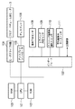
図3は本実施形態のエアバッグ装置の制御部のブロック図である。CPU101はエアバッグ装置全体の制御を司るプロセッサであり、特に後述する処理を実行する。ROM(リードオンリメモリ)102は後述する各処理のプログラムの他、固定的なデータを記憶するメモリである。RAM(ランダムアクセスメモリ)103はCPU101によって処理されるプログラムのワークエリアを有し、可変データ等を記憶する。これらのROM102及びRAM103としては他の記憶手段を採用してもよいことはいうまでもない。
【0032】
モータドライブ回路104は、CPU101の命令に従って、上述したブロア・バキューム用モータ3を回転駆動するドライブ回路である。ディスプレイ106は各種情報を表示する表示器であり、後述するように本実施形態ではエアバッグ1を格納状態へ復帰する方法を案内する案内情報の表示や、障害物との衝突が検出された場合にその警告を発する表示等が出力される。なお、本実施形態ではこれらの情報をディスプレイ106により出力するようにしているが、これに限られず他の出力手段、例えば音声の出力装置を設けて音声により出力してもよい。
【0033】
図4は車両のインストルメントパネル部の構成例を示す図であり、同図に示すように、ディスプレイ106は、乗員が見易いように、例えばハンドルの右側に配設される。ディスプレイ106はディスプレイコントローラ105を介してCPU101に接続されており、CPU101の命令により各種情報を表示することになる。
【0034】
インターフェース107は、CPU101と以下に述べる各デバイスとの間における情報の入力又は出力を中継するものであり、各デバイスの種類に応じて一又は複数設けられる。また、本実施形態ではこのインターフェース107を介して、車両全体の制御を司る主制御部とCPU101との間で情報の入出力を行う。CPU101は車両の主制御部から、車両の走行速度、加速度といった各種情報を常時取得し、後述する処理において利用する。
【0035】
衝突予知センサ108は種々の構成のものを採用可能であるが、例えば、超音波、レーザ光或いは電波等を車両前方に発射すると共にその反射波あるいは反射光を受信することで、車両前方に存在する障害物の距離、大きさ、移動速度等を検出する。
【0036】
エアバッグ復帰用操作スイッチ110は、乗員等の操作者が操作可能に設けられ、展開したエアバッグ1の格納状態への復帰を指示するためのスイッチである。図4はその構成例を示しており、ディスプレイ106の下の扉112を開くと押しボタン型のエアバッグ復帰用操作スイッチ110が現れる。
【0037】
警告解除用キースイッチ111は、障害物との衝突が検出された場合にディスプレイ106により表示される警告を解除するための情報を入力するスイッチである。本実施形態では、この警告を解除する解除条件をROM102に格納しておき、キースイッチ111から入力された情報が、この解除条件に合致する場合に警告が解除される。図4はその構成例を示しており、ディスプレイの下の扉112を開くとテンキースイッチとして構成された警告解除用キースイッチ111が現れる。解除条件として本実施形態では数字列からなるパスワードを想定するが、他の形式のものであってもよい。
【0038】
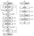
次に、係る構成からなるエアバッグ装置におけるCPU101の処理について説明する。図5(a)は衝突予知に基づくエアバッグ1の展開処理を示すフローチャートである。S1では衝突予知処理を行う。ここでは衝突予知センサ108の検出結果に基づき衝突する可能性があるか否かを判定する。S2ではS1の処理の結果、衝突が予知された場合にはS3へ進み、そうでない場合はS1の処理を繰り返す。
【0039】
S3では車両の主制御部から取得した車両の走行速度に基づき、車両が徐行中であるか否かを判定し、徐行中の場合はS1へ戻り徐行中ではない場合はS4へ進む。車両が例えば10km/h未満で徐行している場合には衝突が予知されていても実際に衝突する可能性が低いか、或いは衝突しても大事に至らないことが予想されるため、本実施形態ではエアバッグ1の展開頻度を低減すべく、エアバッグ1を展開しないようにしている。尤も、このような徐行中であってもエアバッグ1を展開するようにしてもよいことはいうまでもない。
【0040】
S4ではエアバッグ1を展開する処理を行う。ここではブロア・バキューム用モータ3を回転駆動し、エアバッグ1内に空気を噴出することでエアバッグ1を展開する。S5ではインターフェース107を介して車両の主制御部に対して走行禁止指示を出力する。これにより主制御部は車両を直ちに停車させるか、或いは、既に停車中の場合は走行を禁じるように車両を制御することになる。こうすることで、エアバッグが展開等された状態のまま車両が走行することが防止され、車両走行時の安全性をより向上することができる。
【0041】
S6では衝突検出処理を行う。ここでは一定時間中エアバッグ内圧センサ109の検出結果を取得し、そのピーク値を抽出する。S7ではS6の処理結果に基づいて、障害物と衝突したか否かを判定する。ここではS6で抽出したピーク値が所定の閾値を超えた場合に衝突したと判定する。衝突したと判定した場合はS8へ進み、そうでない場合はエアバッグ格納処理へ処理を移行する。
【0042】
S8では警告処理を行う。ここでは、ディスプレイ106に、「衝突しました。」といった警告が表示される。この警告は解除されるまで継続して行われる。その際、表示の内容は衝突を示すアイコン等にしてもよい。このようにすることで、衝突が実際に生じた場合に、乗員等に警告がなされ、これを認識させることができる。展開したエアバッグ1の存在により、乗員等は障害物との衝突が実際に起こったかどうかが必ずしも分かるわけではないが、このような警告により、実際には衝突が生じておらず展開したエアバッグ1を復帰させてもよいのか、そうではなく実際に衝突が生じておりエアバッグ1を復帰させることが望ましくないのか、を乗員等が判断でき利便性がよい。
【0043】
次に、展開したエアバッグ1の格納処理について説明する。図5(b)はエアバッグ格納処理を示すフローチャートである。S11ではエアバッグ1の格納を規制する処理を行う。ここでは、車両の主制御部から取得した情報に基づいて車両が走行中か否かを判定し、走行中の場合には停車するまで次の処理への移行が禁じられる。本実施形態では上述したS5の処理により車両の走行が禁止されるはずであるが、何らかの障害により車両の走行が禁止されなかった場合、或いは、S5の処理を省略した構成を採用した場合、においても車両の走行中におけるエアバッグ1の格納を規制するようにしたものである。このような規制をすることで、例えば、車両走行時の風圧や路面との干渉等との要因により、エアバッグ1が格納状態に復帰できないという状況を防止することが可能となる。
【0044】
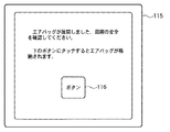
S12では案内情報の出力処理を行う。ここではディスプレイ106に、展開したエアバッグ1を格納状態に復帰する方法を案内する情報が表示される。本実施形態の場合、操作スイッチ110を操作することでエアバッグ1の復帰が開始されるので、ディスプレイ106には、例えば、「エアバッグが展開しました。周囲の安全を確認してください。下の扉を開いて丸いボタンを押すとエアバッグが格納されます。」といった案内情報が表示される。このようにエアバッグ1の復帰手順が案内されので、乗員等は誤ることなくエアバッグ1を格納状態に復帰させることができる。
【0045】
S13ではエアバッグ復帰処理を行う。エアバッグ復帰処理は操作スイッチ110に対する操作があったことを条件に開始される。従って、乗員等の操作者はエアバッグ1に対する異物等の巻き込み等がないことの確認等、周囲の安全性を確認した上でエアバッグ1を格納状態に復帰させることを指示することができ、復帰時の安全性をより向上できる。
【0046】
図6(a)及び(b)はそれぞれエアバッグ復帰処理の例を示すフローチャートである。なお、図6(a)及び(b)の処理は、いずれかを固定的に採用せず、乗員等が選択できるようにしてもよい。
【0047】
まず図6(a)の例は、一旦操作スイッチ110に対する操作があれば格納完了まで展開されたエアバッグ1の復帰動作を継続するものである。
【0048】
S21では操作スイッチ110が押されたか否かを判定する。押された場合はS22へ進み、そうでない場合は操作待ちとなる。S22では、予め定めた時間の経過を待つ。このような待ち時間を設けたのは、操作スイッチ110を操作した乗員等が車室内から車外へ出てエアバッグ1の周囲の安全性を確認する時間与えたものである。このように操作スイッチ110に対する操作があった後、すぐに復帰動作を開始しないことで、予め定めた時間だけこれを遅らせることで、復帰時の安全性をより向上することができる。
【0049】
S23ではブロア・バキューム用モータ3を回転駆動し、エアバッグ1内の空気を吸引することでエアバッグ1を格納状態へ復帰させる。モータ3は次のS24においてエアバッグ1が格納部2に格納されたと判定されるまで駆動される。エアバッグ1が格納されたか否かは例えば格納部2の先端部にセンサを設けて、エアバッグ1が格納部2から飛び出しているか否かを検出して判定することが挙げられる。エアバッグ1の格納が完了するとS25においてモータ3の回転駆動を停止し、処理が終了する。
【0050】
このように図6(a)のエアバッグ復帰処理では、乗員等の操作者は一旦操作スイッチ110に対して操作をすれば、その後に操作を要求されることなく、操作者はエアバッグ1の格納状態への復帰を注視することができ、安全性を向上できる。
【0051】
次に図6(b)の例は、操作スイッチ110に対する操作があった場合、その後の操作スイッチ110に対する操作に応じて、展開されたエアバッグ1の復帰動作を中止するようにしたものである。S31では操作スイッチ110が押されたか否かを判定する。押された場合はS32へ進み、そうでない場合はS33へ進む。
【0052】
S32ではブロア・バキューム用モータ3を回転駆動し、エアバッグ1内の空気を吸引することでエアバッグ1を格納状態へ復帰させる。その後S34へ進む。一方、S33ではモータ3が回転駆動中の場合はこれを停止させ、停止中の場合はそのままの状態を維持する。このように本例では操作者が操作スイッチ110を押している間だけ復帰動作が行われることになる。S34ではエアバッグ1が格納部2に格納されたか否かを判定する。エアバッグ1の格納が完了するとS35においてモータ3の回転駆動を停止し、処理が終了する。
【0053】
このように図6(b)のエアバッグ復帰処理では、乗員等の操作者の操作に応じて復帰処理が中断されるので例えばエアバッグ1の復帰中に異物等が巻き込まれたことが確認された場合、操作スイッチ110から手を離せばエアバッグの復帰動作を中止することができ、復帰時の安全性をより向上することができる。
【0054】
次に、図5(b)に戻りS14ではS5で車両の主制御部に出力した走行禁止指示を解除すべく、インターフェース107を介して主制御部に走行許可指示を出力する。これ以降、車両が走行可能となる。
【0055】
以上述べた通り、本実施形態のエアバッグ装置は、乗員等が自らエアバッグ1を反復して使用することが可能となる。従って、障害物及び車両自体の保護を図る上で、衝突の誤予知が頻発してもこれに対応することができる。また、展開されたエアバッグ1の復帰は操作スイッチ110に対する操作があった場合に行われるので、乗員等の操作者は周囲の安全性を確認した上でエアバッグ1を格納状態に復帰させることを指示することができ、エアバッグ1復帰時の安全性をより向上できる。
【0056】
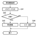
次に、上述したS8の警告を解除する処理について説明する。図7は警告解除処理のフローチャートである。S41では警告解除用キースイッチ111からパスワードの入力を受けつける。入力されたパスワードはディスプレイ106に表示されるようにしてもよい。入力されたパスワードが確定すると、S42へ進み、ROM102に格納されたパスワードと照合され、これと合致するか否かが判定される。合致する場合S43へ進み警告が解除される。これによりディスプレイ106から警告の表示が消えることになる。S42において合致しないと判定された場合にはS44へ進み、ディスプレイ106にエラー表示がなされ、再度の入力が促される。
【0057】
このようにパスワードの照合を行うことでディスプレイ106による警告が安易に解除されることを防止することができる。本実施形態ではこのように衝突が生じた場合に警告を発し、解除されるまで警告を維持することで、事故が発生した事実を保存しておくことができる。この場合、パスワードのような解除条件に合致する情報が、例えば、警察官やディーラといった特定の者にのみ知らされたものとすることが望ましく、こうすることで権限のある者のみが警告を解除することが可能となり、事故をおこした乗員等が事故発生の事実をそれらの者に報告する機会が促進される。
【0058】
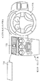
なお、本実施形態ではパスワードの照合により警告を解除するようにしたが、これに代えて、警告の解除を指示するための解除指示スイッチ等を設け、これを車両の、警察官やディーラといった特定の者にのみ知らされた箇所に設置されるようにしても同様の効果が得られる。図10はその配置例を示した図であり、解除指示スイッチ113はセンターコンソール上部のカバー114を取り去ることで現れるようにしている。解除指示スイッチ113が押されることで警告が解除される。カバー114は特定の器具等を用いなければ取り去ることができないようにすることができる。
【0059】
<操作スイッチの他の実施形態>
以下、上述した操作スイッチ110の他の例について説明する。図8はディスプレイ106と操作スイッチ110とを一つのタッチパネル115で構成した例である。このタッチパネル115は例えば車両のインストルメントパネルに配設することができる。図8では、展開したエアバッグ1を格納状態に復帰する方法を案内する案内情報が表示されると共に、操作スイッチ110に代わるボタン116が表示されている態様を示している。乗員等の操作者はこのボタン116を押すことでエアバッグ1の格納状態への復帰を指示することができる。このようなタッチパネル115を採用することで、案内情報等の各種情報を表示することに加えて、エアバッグ1の復帰に必要な場合のみ操作ボタン116が現れるようにすることができ、利用頻度がそう多くないと考えられる操作スイッチ110をを常設する必要がなくなる。
【0060】
次に、図9(a)は操作スイッチ110を、展開されたエアバッグ1の復帰状況を乗員等の操作者が視認可能な位置に設けた例を示す図である。同図の例では車体のフロントボディ側方内部に操作スイッチ110を設け、扉117を開くことで操作スイッチ110が現れるように構成している。このようにエアバッグ1に近接した位置であれば、乗員等の操作者はエアバッグ1の挙動を確認しながら操作スイッチ110を操作することが可能となる。従って、操作者はエアバッグ1の周囲の安全性を確認しながら操作を行うことができ、エアバッグ1の復帰時の安全性をより向上することができる。なお、操作スイッチ110はこの配置以外にもエアバッグ1の復帰状況を操作者が視認可能な種々の位置に設けることができ、例えば、フロントボディ内のエンジンルームに配設してもよい。
【0061】
次に、図9(b)は操作スイッチ110を携帯型の無線通信端末器118により構成した例を示す図である。無線通信端末器118は、操作により例えば赤外線や電波等の信号を発信する端末器であり、エアバッグ装置はこの信号を受信した場合に、展開されたエアバッグ1の復帰動作を開始する。この構成の場合、乗員等の操作者は車両外部においてエアバッグ1の周囲の安全性を確認しながら復帰動作の指示を行うことができ、復帰時の安全性をより向上することができる。なお、車両のリモコンキーを無線通信端末器118として利用するように構成してもよく、この場合、エアバッグ1が展開された時に操作があった際、車両のドアの開錠ではなく、エアバッグ1の復帰の指示と判断するようにすることもできる。
【0062】
次に、図9(c)は、操作スイッチ110を、乗員等の操作者が両手でなければ同時に操作できないように設けられた複数の操作部を備えるように構成した例を示す図である。同図の例では、シートの両側に操作部として2つのレバー型のスイッチ119を設けた例を示している。この構成の場合、2つのレバー型のスイッチ119を同時に矢印の方向へ引き上げれば、エアバッグ1を格納状態に復帰する操作がなされたことになり、いずれか一方の場合はエアバッグ1の復帰動作が開始されない。こうすることで、操作者は両手を使わなければエアバッグ1の復帰が行えないので、例えば、乗員がエアバッグ1を格納状態に復帰させながら車両を運転する等、不適切な行為を防止することができる。なお、図9(c)の例以外にも種々の配置を採用することができ、例えばインストルメントパネルにおいて、ハンドルの両側に操作部としてスイッチをそれぞれ配設する構成を採用してもよい。
【0063】
【発明の効果】
以上述べた通り、本発明のエアバッグ装置によれば、障害物及び車両自体の保護を図る上で、頻発的な衝突予知に対応することができる。更に、操作手段に対する操作があった場合にエアバッグを格納状態に復帰するので、乗員等の操作者は周囲の安全性を確認した上で、エアバッグを格納状態に復帰できる。
【図面の簡単な説明】
【図1】本発明の一実施形態に係るエアバッグ装置を適用した車両の外観図であり、(a)はエアバッグの格納状態を、(b)はエアバッグの展開状態を示している。
【図2】(a)乃至(c)はエアバッグ1の展開及び格納状態への復帰を行うブロア・バキューム装置の動作説明図、(d)はエアバッグ1の展開及び格納状態への復帰を行う他の装置の構成例を示す図である。
【図3】本発明の一実施形態に係るエアバッグ装置の制御部のブロック図である。
【図4】車両のインストルメントパネル部の構成例を示す図である。
【図5】(a)は衝突予知に基づくエアバッグ1の展開処理を示すフローチャート、(b)はエアバッグ格納処理を示すフローチャートである。
【図6】(a)及び(b)はそれぞれエアバッグ復帰処理の例を示すフローチャートである。
【図7】警告解除処理のフローチャートである。
【図8】ディスプレイ106と操作スイッチ110とを一つのタッチパネル115で構成した例を示す図である。
【図9】(a)は操作スイッチ110を、展開されたエアバッグ1の復帰状況を乗員等の操作者が視認可能な位置に設けた例を示す図、(b)は操作スイッチ110を携帯型の無線通信端末器118により構成した例を示す図、(c)は、操作スイッチ110を、乗員等の操作者が両手でなければ同時に操作できないように設けられた複数の操作部を備えるように構成した例を示す図である。
【図10】解除指示スイッチ113の配置例を示した図である。
【符号の説明】
1 エアバッグ
2 格納部
3 ブロア・バキューム用モータ
106 ディスプレイ
108 衝突予知センサ
109 エアバッグ内圧センサ
110 エアバッグ復帰用操作スイッチ
111 警告解除用キースイッチ
115 タッチパネル
118 無線通信端末器
119 レバー型のスイッチ[0001]
BACKGROUND OF THE INVENTION
The present invention relates to a vehicle airbag device.
[0002]
[Prior art]
Various techniques have been proposed for protecting passengers from vehicle collisions against obstacles. A typical example is an airbag that is deployed in a passenger compartment when a vehicle collides. In addition, a technique for predicting a collision between a vehicle and an obstacle in advance and protecting an occupant has been proposed. For example,
[0003]
On the other hand, as a technique for improving the safety of a vehicle at the time of a collision, a technique for protecting not only an occupant but also an obstacle or the vehicle itself has been proposed. For example,
[0004]
[Patent Document 1]
JP 2000-142321 A
[Patent Document 2]
JP-A-6-239198
[0005]
[Problems to be solved by the invention]
Here, in order to sufficiently protect the obstacles and the vehicle itself, it is desirable to predict the collision if there is a danger, whether or not the collision actually occurs, and the airbag is deployed earlier. In order to improve the protection performance, it is desirable that the sensitivity of collision prediction is high. However, if the sensitivity of collision prediction is increased, erroneous prediction of collisions will occur frequently, and the frequency of deploying airbags will increase accordingly. In this regard, once the airbag is deployed, it is necessary to return it to its original stored state, but it is not assumed that the conventional airbag apparatus will be used many times. Further, when returning the deployed airbag to its original retracted state, it is desirable to be able to confirm the safety of the surroundings, such as whether foreign matter or the like is caught in the restored airbag.
[0006]
Therefore, the main object of the present invention is to cope with frequent collision predictions in order to protect the obstacles and the vehicle itself, and keep the deployed airbag in a retracted state while confirming the safety of the surroundings. An object of the present invention is to provide an airbag device that can be restored.
[0009]
[Means for Solving the Problems]
According to the present invention, the airbag stored in a deployable manner in front of the outside of the vehicle and the airbag in the stored state can be repeatedly deployed, and the airbag can be used when a collision with an obstacle is predicted. Deployment means for deploying, an operation means for receiving an operation by an operator, and a return means for returning the deployed airbag to a stored state when there is an operation on the operation means,The return means continues the return operation of the deployed airbag until the storage is completed once the operation means is operated.An air bag device is provided..
According to the airbag device of the present invention, it is possible to repeatedly use the airbag by providing the deployment means and the return means. Therefore, in order to protect the obstacles and the vehicle itself, it is possible to cope with the occurrence of frequent mispredictions of collisions. Further, according to the present invention, when the operation means is operated, the airbag is returned to the retracted state, so that an operator such as an occupant returns the airbag to the retracted state after confirming the surrounding safety. Can be instructed to improve the safety when returning the airbag. Also,Once the operator performs an operation on the operation means, the operator can watch the return of the airbag to the retracted state without being requested for the operation thereafter, thereby improving safety.
[0010]
Also, in the present inventionAccording to the present invention, the airbag stored in a deployable front in front of the vehicle and the airbag in the retracted state can be repeatedly deployed, and the airbag is deployed when a collision with an obstacle is predicted. A deployment means, an operation means for receiving an operation by an operator, and a return means for returning the deployed airbag to a retracted state when an operation is performed on the operation means,The return means, when there is an operation on the operation means, stops the return operation of the deployed airbag according to the subsequent operation on the operation means.An air bag device is provided..
According to the airbag device of the present invention, it is possible to repeatedly use the airbag by providing the deployment means and the return means. Therefore, in order to protect the obstacles and the vehicle itself, it is possible to cope with the occurrence of frequent mispredictions of collisions. Further, according to the present invention, when the operation means is operated, the airbag is returned to the retracted state, so that an operator such as an occupant returns the airbag to the retracted state after confirming the surrounding safety. Can be instructed to improve the safety when returning the airbag. Also,For example, when it is confirmed that a foreign object or the like is caught during the return of the airbag, the return operation of the airbag can be stopped by the operation on the operation means, and the safety at the time of returning the airbag is further improved. be able to.
[0011]
Also, in the present inventionAccording to the present invention, the airbag stored in a deployable front in front of the vehicle and the airbag in the retracted state can be repeatedly deployed, and the airbag is deployed when a collision with an obstacle is predicted. A deployment means, an operation means for receiving an operation by an operator, and a return means for returning the deployed airbag to a retracted state when an operation is performed on the operation means,The return means returns the deployed airbag to a retracted state after elapse of a predetermined time after an operation on the operation means.An air bag device is provided..
According to the airbag device of the present invention, it is possible to repeatedly use the airbag by providing the deployment means and the return means. Therefore, in order to protect the obstacles and the vehicle itself, it is possible to cope with the occurrence of frequent mispredictions of collisions. Further, according to the present invention, when the operation means is operated, the airbag is returned to the retracted state, so that an operator such as an occupant returns the airbag to the retracted state after confirming the surrounding safety. Can be instructed to improve the safety when returning the airbag. Also,The operator is given time to confirm the safety around the airbag after the operation of the operation means, and the safety when returning the airbag can be further improved.
[0012]
Also, in the present inventionAccording to the present invention, the airbag stored in a deployable front in front of the vehicle and the airbag in the retracted state can be repeatedly deployed, and the airbag is deployed when a collision with an obstacle is predicted. A deployment means, an operation means for receiving an operation by an operator, and a return means for returning the deployed airbag to a retracted state when an operation is performed on the operation means,The operation means includes a plurality of operation units provided so that an operator can operate only with both hands at the same time, and the return unit includes the airbag deployed when the plurality of operation units are operated simultaneously. Return to the storage stateAn air bag device is provided..
According to the airbag device of the present invention, it is possible to repeatedly use the airbag by providing the deployment means and the return means. Therefore, in order to protect the obstacles and the vehicle itself, it is possible to cope with the occurrence of frequent mispredictions of collisions. Further, according to the present invention, when the operation means is operated, the airbag is returned to the retracted state, so that an operator such as an occupant returns the airbag to the retracted state after confirming the surrounding safety. Can be instructed to improve the safety when returning the airbag. Also,Since the operator cannot return the airbag without using both hands, for example, an occupant operates the operation means to prevent inappropriate actions such as driving the vehicle while returning the airbag to the retracted state. can do.
[0015]
Also, in the present inventionAccording to the present invention, the airbag stored in a deployable front in front of the vehicle and the airbag in the retracted state can be repeatedly deployed, and the airbag is deployed when a collision with an obstacle is predicted. Deployment means, operation means for accepting an operation by an operator, return means for returning the deployed airbag to a retracted state when an operation is performed on the operation means,Output means for outputting guidance information for guiding a method for returning the airbag to the retracted state when the airbag is deployed.And an airbag device characterized by comprising.
According to the airbag device of the present invention, it is possible to repeatedly use the airbag by providing the deployment means and the return means. Therefore, in order to protect the obstacles and the vehicle itself, it is possible to cope with the occurrence of frequent mispredictions of collisions. Further, according to the present invention, when the operation means is operated, the airbag is returned to the retracted state, so that an operator such as an occupant returns the airbag to the retracted state after confirming the surrounding safety. Can be instructed to improve the safety when returning the airbag. Also,Since the procedure for returning the airbag is guided, the operator can return the airbag to the retracted state without error.
[0016]
In this case, the output unit may be a touch panel that displays the guide information, and the operation unit may be an operation button displayed on the touch panel together with the guide information. By doing so, the operation means appears as the operation button only when it is necessary to return the airbag, and it is not necessary to permanently install the operation means.
[0017]
Also, in the present inventionAccording to the present invention, the airbag stored in a deployable front in front of the vehicle and the airbag in the retracted state can be repeatedly deployed, and the airbag is deployed when a collision with an obstacle is predicted. Deployment means, operation means for accepting an operation by an operator, return means for returning the deployed airbag to a retracted state when an operation is performed on the operation means,Output means for outputting a travel prohibition instruction for the vehicle to the control unit of the vehicle when the airbag is not in a retracted state.And an airbag device characterized by comprising.
According to the airbag device of the present invention, it is possible to repeatedly use the airbag by providing the deployment means and the return means. Therefore, in order to protect the obstacles and the vehicle itself, it is possible to cope with the occurrence of frequent mispredictions of collisions. Further, according to the present invention, when the operation means is operated, the airbag is returned to the retracted state, so that an operator such as an occupant returns the airbag to the retracted state after confirming the surrounding safety. Can be instructed to improve the safety when returning the airbag. Also,It is possible to prevent the vehicle from traveling while the airbag is deployed and the like, and the safety during vehicle traveling can be further improved.
[0018]
Also, in the present inventionAccording to the present invention, the airbag stored in a deployable front in front of the vehicle and the airbag in the retracted state can be repeatedly deployed, and the airbag is deployed when a collision with an obstacle is predicted. Deployment means, operation means for accepting an operation by an operator, return means for returning the deployed airbag to a retracted state when an operation is performed on the operation means,Restricting means for restricting return of the airbag to the retracted state by the returning means during travel of the vehicleAnd an airbag device characterized in that.
According to the airbag device of the present invention, it is possible to repeatedly use the airbag by providing the deployment means and the return means. Therefore, in order to protect the obstacles and the vehicle itself, it is possible to cope with the occurrence of frequent mispredictions of collisions. Further, according to the present invention, when the operation means is operated, the airbag is returned to the retracted state, so that an operator such as an occupant returns the airbag to the retracted state after confirming the surrounding safety. Can be instructed to improve the safety when returning the airbag. Also,It is possible to prevent a situation in which the airbag cannot return to the retracted state due to factors such as wind pressure during vehicle travel and interference with the road surface.
[0023]
DETAILED DESCRIPTION OF THE INVENTION
Preferred embodiments of the present invention will be described below with reference to the drawings. 1A and 1B are external views of a vehicle to which an airbag device according to an embodiment of the present invention is applied. FIG. 1A shows a stored state of the airbag, and FIG. 1B shows a deployed state of the airbag. In the case of the present embodiment, as shown in FIG. 1A, a
[0024]
If the
[0025]
FIGS. 2A to 2C are explanatory views of the operation of the blower / vacuum device for deploying the
[0026]
A
[0027]
On the other hand, when the deployed
[0028]
In the present embodiment, the
[0029]
FIG. 2D is a diagram illustrating a configuration example of another device that deploys the
[0030]
When the
[0031]
FIG. 3 is a block diagram of a control unit of the airbag apparatus according to the present embodiment. The
[0032]
The
[0033]
FIG. 4 is a diagram showing a configuration example of an instrument panel portion of a vehicle. As shown in the figure, the
[0034]
The
[0035]
The
[0036]
The airbag
[0037]
The warning canceling
[0038]
Next, processing of the
[0039]
In S3, it is determined whether or not the vehicle is traveling slowly based on the traveling speed of the vehicle acquired from the main control unit of the vehicle. If the vehicle is traveling slowly, the process returns to S1, and if not, the process proceeds to S4. For example, if the vehicle is slowing down at a speed of less than 10 km / h, the possibility of an actual collision is low even if a collision is predicted. In the embodiment, the
[0040]
In S4, a process of deploying the
[0041]
In S6, a collision detection process is performed. Here, the detection result of the airbag
[0042]
In S8, warning processing is performed. Here, a warning such as “Collision” is displayed on the
[0043]
Next, the storing process of the deployed
[0044]
In S12, guidance information output processing is performed. Here, information for guiding the method of returning the deployed
[0045]
In S13, an air bag return process is performed. The airbag recovery process is started on condition that the
[0046]
FIGS. 6A and 6B are flowcharts showing examples of the airbag return processing. Note that either one of the processes in FIGS. 6A and 6B may not be fixedly adopted, and may be selected by an occupant or the like.
[0047]
First, in the example of FIG. 6A, once the
[0048]
In S21, it is determined whether or not the
[0049]
In S23, the blower /
[0050]
As described above, in the airbag return process of FIG. 6A, once an operator such as an occupant operates the
[0051]
Next, in the example of FIG. 6B, when the
[0052]
In S32, the blower /
[0053]
As described above, in the airbag return process of FIG. 6B, the return process is interrupted according to the operation of an operator such as an occupant, so it is confirmed that, for example, a foreign object or the like has been caught during the return of the
[0054]
Next, returning to FIG. 5B, in S14, a travel permission instruction is output to the main control unit via the
[0055]
As described above, the airbag apparatus according to the present embodiment enables an occupant or the like to repeatedly use the
[0056]
Next, the process for canceling the warning in S8 will be described. FIG. 7 is a flowchart of the warning cancellation process. In S41, the password input is received from the warning canceling
[0057]
By performing password verification in this way, it is possible to prevent the warning from the
[0058]
In this embodiment, the warning is canceled by collating the password. Instead, a release instruction switch for instructing the cancellation of the warning is provided, and this is specified as a police officer or dealer of the vehicle. The same effect can be obtained even if it is installed at a location that is known only to those who are not. FIG. 10 is a diagram showing an example of the arrangement, and the
[0059]
<Other Embodiments of Operation Switch>
Hereinafter, another example of the
[0060]
Next, FIG. 9A is a diagram illustrating an example in which the
[0061]
Next, FIG. 9B is a diagram illustrating an example in which the
[0062]
Next, FIG.9 (c) is a figure which shows the example comprised so that the
[0063]
【The invention's effect】
As described above, according to the airbag device of the present invention, it is possible to cope with frequent collision prediction in protecting the obstacle and the vehicle itself. Furthermore, since the airbag is returned to the retracted state when the operation means is operated, an operator such as an occupant can return the airbag to the retracted state after confirming the safety of the surroundings.
[Brief description of the drawings]
FIGS. 1A and 1B are external views of a vehicle to which an airbag device according to an embodiment of the present invention is applied, in which FIG. 1A shows a stored state of the airbag and FIG. 1B shows a deployed state of the airbag;
FIGS. 2A to 2C are explanatory views of the operation of the blower / vacuum device that performs deployment and return of the
FIG. 3 is a block diagram of a control unit of the airbag apparatus according to the embodiment of the present invention.
FIG. 4 is a diagram illustrating a configuration example of an instrument panel unit of a vehicle.
5A is a flowchart showing a deployment process of the
FIGS. 6A and 6B are flowcharts showing examples of airbag return processing, respectively.
FIG. 7 is a flowchart of warning cancellation processing.
FIG. 8 is a diagram illustrating an example in which a display and an
9A is a view showing an example in which the
10 is a diagram showing an example of the arrangement of release instruction switches 113. FIG.
[Explanation of symbols]
1 Airbag
2 storage
3 Blower / vacuum motor
106 display
108 Collision prediction sensor
109 Airbag internal pressure sensor
110 Airbag return switch
111 Key switch for warning release
115 touch panel
118 Wireless communication terminal
119 Lever type switch
Claims (8)
格納状態にある前記エアバッグを繰り返し展開可能であって、障害物との衝突が予知された場合に前記エアバッグを展開する展開手段と、
操作者による操作を受けつける操作手段と、
前記操作手段に対する操作があった場合に、展開された前記エアバッグを格納状態に復帰させる復帰手段と、を備え、
前記復帰手段は、
一旦前記操作手段に対する操作があれば、格納完了まで、展開された前記エアバッグの復帰動作を継続することを特徴とするエアバッグ装置。 An airbag stored in a deployable manner in front of the outside of the vehicle;
Deployment means that can repeatedly deploy the airbag in a retracted state and that deploys the airbag when a collision with an obstacle is predicted;
An operation means for receiving an operation by an operator;
A return means for returning the deployed airbag to a retracted state when the operation means is operated,
The return means includes
Once any operation on said operating unit, until completion of storage, features and to Rue airbag apparatus to continue the recovery operation of the air bag deployed.
格納状態にある前記エアバッグを繰り返し展開可能であって、障害物との衝突が予知された場合に前記エアバッグを展開する展開手段と、
操作者による操作を受けつける操作手段と、
前記操作手段に対する操作があった場合に、展開された前記エアバッグを格納状態に復帰させる復帰手段と、を備え、
前記復帰手段は、
前記操作手段に対する操作があった場合、その後の前記操作手段に対する操作に応じて、展開された前記エアバッグの復帰動作を中止することを特徴とするエアバッグ装置。 An airbag stored in a deployable manner in front of the outside of the vehicle;
Deployment means that can repeatedly deploy the airbag in a retracted state and that deploys the airbag when a collision with an obstacle is predicted;
An operation means for receiving an operation by an operator;
A return means for returning the deployed airbag to a retracted state when the operation means is operated,
The return means includes
Wherein when a manipulation for the operation means, then in response to an operation on the operation means, wherein the to Rue airbag device that stops the return movement of the air bag deployed.
格納状態にある前記エアバッグを繰り返し展開可能であって、障害物との衝突が予知された場合に前記エアバッグを展開する展開手段と、
操作者による操作を受けつける操作手段と、
前記操作手段に対する操作があった場合に、展開された前記エアバッグを格納状態に復帰させる復帰手段と、を備え、
前記復帰手段は、
前記操作手段に対する操作があった後、予め定めた時間の経過後に、展開された前記エアバッグを格納状態に復帰させることを特徴とするエアバッグ装置。 An airbag stored in a deployable manner in front of the outside of the vehicle;
Deployment means that can repeatedly deploy the airbag in a retracted state and that deploys the airbag when a collision with an obstacle is predicted;
An operation means for receiving an operation by an operator;
A return means for returning the deployed airbag to a retracted state when the operation means is operated,
The return means includes
Wherein after an operation on the operation unit in advance after the passage of predetermined time, features and to Rue airbag apparatus that is returning the airbag deployed in the storage state.
格納状態にある前記エアバッグを繰り返し展開可能であって、障害物との衝突が予知された場合に前記エアバッグを展開する展開手段と、
操作者による操作を受けつける操作手段と、
前記操作手段に対する操作があった場合に、展開された前記エアバッグを格納状態に復帰させる復帰手段と、を備え、
前記操作手段は、
操作者が両手でなければ同時に操作できないように設けられた複数の操作部を備え、
前記復帰手段は当該複数の操作部が同時に操作された場合に展開された前記エアバッグを格納状態に復帰させることを特徴とするエアバッグ装置。 An airbag stored in a deployable manner in front of the outside of the vehicle;
Deployment means that can repeatedly deploy the airbag in a retracted state and that deploys the airbag when a collision with an obstacle is predicted;
An operation means for receiving an operation by an operator;
A return means for returning the deployed airbag to a retracted state when the operation means is operated,
The operation means includes
It is equipped with a plurality of operation units provided so that the operator can operate only with both hands at the same time,
It said return means, characterized and to Rue airbag apparatus that is returning the airbag deployed when the plurality of operation portions are simultaneously operated in the storage state.
格納状態にある前記エアバッグを繰り返し展開可能であって、障害物との衝突が予知された場合に前記エアバッグを展開する展開手段と、
操作者による操作を受けつける操作手段と、
前記操作手段に対する操作があった場合に、展開された前記エアバッグを格納状態に復帰させる復帰手段と、
前記エアバッグが展開された場合に、当該エアバッグを格納状態へ復帰する方法を案内する案内情報を出力する出力手段と、を備えたことを特徴とするエアバッグ装置。 An airbag stored in a deployable manner in front of the outside of the vehicle;
Deployment means that can repeatedly deploy the airbag in a retracted state and that deploys the airbag when a collision with an obstacle is predicted;
An operation means for receiving an operation by an operator;
A return means for returning the deployed airbag to a retracted state when the operation means is operated;
When said air bag is deployed, features and to Rue airbag apparatus further comprising output means for outputting the guidance information to guide the process to return the air bag to the storage state, the.
前記案内情報を表示するタッチパネルであり、
前記操作手段は、前記案内情報と共に前記タッチパネル上に表示される操作ボタンであることを特徴とする請求項5に記載のエアバッグ装置。The output means is
A touch panel for displaying the guidance information;
6. The airbag device according to claim 5 , wherein the operation means is an operation button displayed on the touch panel together with the guidance information.
格納状態にある前記エアバッグを繰り返し展開可能であって、障害物との衝突が予知された場合に前記エアバッグを展開する展開手段と、
操作者による操作を受けつける操作手段と、
前記操作手段に対する操作があった場合に、展開された前記エアバッグを格納状態に復帰させる復帰手段と、
前記エアバッグが格納状態にない場合に、前記車両の制御部に対して、前記車両の走行禁止指示を出力する出力手段と、を備えたことを特徴とするエアバッグ装置。 An airbag stored in a deployable manner in front of the outside of the vehicle;
Deployment means that can repeatedly deploy the airbag in a retracted state and that deploys the airbag when a collision with an obstacle is predicted;
An operation means for receiving an operation by an operator;
A return means for returning the deployed airbag to a retracted state when the operation means is operated;
Wherein when the airbag is not in the retracted state, the control unit of the vehicle, and output means for outputting a traveling inhibition instruction of the vehicle, characterized and to Rue airbag apparatus further comprising: a.
格納状態にある前記エアバッグを繰り返し展開可能であって、障害物との衝突が予知された場合に前記エアバッグを展開する展開手段と、
操作者による操作を受けつける操作手段と、
前記操作手段に対する操作があった場合に、展開された前記エアバッグを格納状態に復帰させる復帰手段と、
前記車両の走行時に、前記復帰手段による前記エアバッグの格納状態への復帰を規制する規制手段と、を設けたことを特徴とするエアバッグ装置。 An airbag stored in a deployable manner in front of the outside of the vehicle;
Deployment means that can repeatedly deploy the airbag in a retracted state and that deploys the airbag when a collision with an obstacle is predicted;
An operation means for receiving an operation by an operator;
A return means for returning the deployed airbag to a retracted state when the operation means is operated;
Wherein during running of the vehicle, the return means by the features and to Rue airbag apparatus in that a, a restricting means for restricting a return to a storage state of the airbag.
Priority Applications (1)
| Application Number | Priority Date | Filing Date | Title |
|---|---|---|---|
| JP2003137695A JP4196331B2 (en) | 2003-05-15 | 2003-05-15 | Airbag device |
Applications Claiming Priority (1)
| Application Number | Priority Date | Filing Date | Title |
|---|---|---|---|
| JP2003137695A JP4196331B2 (en) | 2003-05-15 | 2003-05-15 | Airbag device |
Publications (2)
| Publication Number | Publication Date |
|---|---|
| JP2004338555A JP2004338555A (en) | 2004-12-02 |
| JP4196331B2 true JP4196331B2 (en) | 2008-12-17 |
Family
ID=33527304
Family Applications (1)
| Application Number | Title | Priority Date | Filing Date |
|---|---|---|---|
| JP2003137695A Expired - Fee Related JP4196331B2 (en) | 2003-05-15 | 2003-05-15 | Airbag device |
Country Status (1)
| Country | Link |
|---|---|
| JP (1) | JP4196331B2 (en) |
Families Citing this family (4)
| Publication number | Priority date | Publication date | Assignee | Title |
|---|---|---|---|---|
| KR100635922B1 (en) * | 2005-02-03 | 2006-10-19 | 김병래 | Bumper with air bag whose operation is controlled by displacement sensor |
| JP2006232090A (en) * | 2005-02-24 | 2006-09-07 | Mazda Motor Corp | Airbag device for vehicle |
| JP4767819B2 (en) * | 2006-11-15 | 2011-09-07 | 本田技研工業株式会社 | Saddle riding |
| CN116001712A (en) * | 2022-12-28 | 2023-04-25 | 北京百度网讯科技有限公司 | Sensor protection method, sensor protection system and automatic driving vehicle |
-
2003
- 2003-05-15 JP JP2003137695A patent/JP4196331B2/en not_active Expired - Fee Related
Also Published As
| Publication number | Publication date |
|---|---|
| JP2004338555A (en) | 2004-12-02 |
Similar Documents
| Publication | Publication Date | Title |
|---|---|---|
| US6749218B2 (en) | Externally deployed airbag system | |
| US10988103B2 (en) | Knee airbag apparatus for autonomous vehicle and method of controlling the same | |
| US6623033B2 (en) | Airbag inflation control system and method | |
| US6755273B2 (en) | Combined airbag inflation and occupant displacement enabling method and apparatus | |
| US9022417B2 (en) | Single side curtain airbag for vehicles | |
| WO2004089704A1 (en) | A pedestrian detecting system | |
| EP2022684B1 (en) | Air bag device for protection of knee, method of developing air bag device for protection of knee, and vehicle | |
| JP2020023235A (en) | Vehicular protection device and vehicle | |
| US7201394B2 (en) | Airbag apparatus | |
| JP2004338555A (en) | Airbag device | |
| KR102819191B1 (en) | Driver airbag system | |
| JP2005199787A (en) | Ground airbag device | |
| JP3013676B2 (en) | Airbag device for side collision | |
| JP2006520714A (en) | Crew protection device | |
| JP4196332B2 (en) | Airbag device | |
| WO2008065964A1 (en) | Curtain airbag device | |
| JPH07132793A (en) | Vehicle collision detection device | |
| JP5613406B2 (en) | Seat belt control device and seat belt system | |
| JP4588438B2 (en) | Occupant protection device, vehicle with occupant protection device | |
| JP4278472B2 (en) | Pedestrian protection device | |
| JP4201258B2 (en) | Pedestrian protection device | |
| JP2923650B2 (en) | Car airbag system | |
| JP4311149B2 (en) | Crew protection device | |
| JPS6364851A (en) | Air bag | |
| KR20100066910A (en) | Control apparatus and control method of external air-bag for a vehicle |
Legal Events
| Date | Code | Title | Description |
|---|---|---|---|
| A621 | Written request for application examination |
Free format text: JAPANESE INTERMEDIATE CODE: A621 Effective date: 20060222 |
|
| A131 | Notification of reasons for refusal |
Free format text: JAPANESE INTERMEDIATE CODE: A131 Effective date: 20080623 |
|
| A521 | Written amendment |
Free format text: JAPANESE INTERMEDIATE CODE: A523 Effective date: 20080731 |
|
| TRDD | Decision of grant or rejection written | ||
| A01 | Written decision to grant a patent or to grant a registration (utility model) |
Free format text: JAPANESE INTERMEDIATE CODE: A01 Effective date: 20080905 |
|
| A01 | Written decision to grant a patent or to grant a registration (utility model) |
Free format text: JAPANESE INTERMEDIATE CODE: A01 |
|
| A61 | First payment of annual fees (during grant procedure) |
Free format text: JAPANESE INTERMEDIATE CODE: A61 Effective date: 20080918 |
|
| FPAY | Renewal fee payment (event date is renewal date of database) |
Free format text: PAYMENT UNTIL: 20111010 Year of fee payment: 3 |
|
| R150 | Certificate of patent or registration of utility model |
Free format text: JAPANESE INTERMEDIATE CODE: R150 |
|
| FPAY | Renewal fee payment (event date is renewal date of database) |
Free format text: PAYMENT UNTIL: 20111010 Year of fee payment: 3 |
|
| FPAY | Renewal fee payment (event date is renewal date of database) |
Free format text: PAYMENT UNTIL: 20121010 Year of fee payment: 4 |
|
| FPAY | Renewal fee payment (event date is renewal date of database) |
Free format text: PAYMENT UNTIL: 20131010 Year of fee payment: 5 |
|
| LAPS | Cancellation because of no payment of annual fees |