JP4196665B2 - Door lock device - Google Patents
Door lock device Download PDFInfo
- Publication number
- JP4196665B2 JP4196665B2 JP2002364040A JP2002364040A JP4196665B2 JP 4196665 B2 JP4196665 B2 JP 4196665B2 JP 2002364040 A JP2002364040 A JP 2002364040A JP 2002364040 A JP2002364040 A JP 2002364040A JP 4196665 B2 JP4196665 B2 JP 4196665B2
- Authority
- JP
- Japan
- Prior art keywords
- lever
- open
- lock
- door
- state
- Prior art date
- Legal status (The legal status is an assumption and is not a legal conclusion. Google has not performed a legal analysis and makes no representation as to the accuracy of the status listed.)
- Expired - Fee Related
Links
Images






Landscapes
- Lock And Its Accessories (AREA)
Description
【0001】
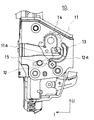
【発明の属する技術分野】
本発明は、ドアロック装置に関する。
【0002】
【従来の技術】
従来のドアロック装置としては、車両ドアに適用可能であると共に車両ボデー側のストライカと係脱可能なラッチ機構と、ラッチ機構をストライカとの係合状態から非係合状態へ作動可能なリフトレバーと、車両ドアに配設された開扉部材の操作により作動するオープンレバーと、車両ドアに配設された施解錠部材の操作によりアンロック位置とロック位置との間を移動可能なロックレバーと、ロックレバーと連動してアンロック位置とロック位置との間を移動可能であると共に、アンロック位置にある場合には前記オープンレバーからの操作によりリフトレバーと該リフトレバーを作動可能な一方向に係合し、ロック位置にある場合にはオープンレバーからの操作によりリフトレバーに対して空振りしかつ空振り状態でロック位置からアンロック位置に移動した場合にリフトレバーと該リフトレバーを作動不可能な他方向に係合するオープン部材とを備えるものが公知となっている。
【0003】
かかる装置では、オープン部材がアンロック位置にある場合をアンロック状態と言い、ロック位置にある場合をロック状態と言う。そして、アンロック状態においては、ドアハンドル等の操作によって、オープン部材がリフトレバーと係合、作動させ、その結果、ラッチ機構のストライカとの係合が外れる。ロック状態においては、ドアハンドル等が操作されても、オープン部材はリフトレバーに対して空振りするためにリフトレバーが作動しない。その結果、ラッチ機構のストライカとの係合が外れないようになっている。
【0004】
これらの装置は、ロック状態において、ドアハンドル等とロックノブ等の施解錠部材を重畳的に操作した場合には、次の様な不具合が起こることが知られている。即ち、ドアハンドルの方が早く操作された場合には、オープン部材がリフトレバーに対して空振りして、ロック状態でのフルストローク位置に移動する。その後、フルストローク位置からアンロック位置の方向に移動する。この際、オープン部材がリフトレバーと他方向に係合するため、アンロック位置方向に移動できないという状態が発生し得る。この際、ロッキングレバーも、オープン部材と連動しているために、アンロック位置方向に移動できないという状態が発生し得る。よって、その後ドアハンドルの操作を元に戻したときは、一度ロックノブを操作したにも関わらず、アンロック状態への切替えが未成立のままの状態となる(この状態をパニック状態と称する)。よって、アンロック状態へ切替えるためには、再度ロックノブを操作する必要があり、操作が煩わしいという不具合があった。この様な不具合は、他にも、人がドアハンドルを操作するためにドアハンドルに手を接近させたことを感知して自動的にロック状態からアンロック状態に切替える様なドアロックシステムにおいても同様に起こり得る。なぜならば、制御のタイミングによっては、自動的なアンロック状態への切替え作動より、手動によるドアハンドル操作の方が早く行われることが起こり得るからである。
【0005】
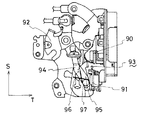
上記の不具合を解決するための装置としては、後述の特許文献1に示されるものが公知となっている。その構成を図16に示した。この装置は、ラッチ機構を車両ボデー側のストライカとの係合状態から非係合状態へ作動可能なリフトレバー90と、車両ドアに配設されたドアハンドル等の操作により作動するオープンレバー91と、車両ドアに配設されたロックノブ等の操作に移動するロックレバー92と、ロックレバー92と連動してアンロック位置とロック位置との間を移動可能であると共に、アンロック位置にある場合にはオープンレバー91からの操作によりリフトレバー90と図示S方向に係合してリフトレバー90を作動させ、ロック位置にある場合にはオープンレバー90に対して空振りするオープン部材93とを備えるドアロック装置である。また、オープン部材93は、オープンレバー91とロックレバー92とを連結するメインリンク94と、メインリンク94に軸97にて回動可能に支持されると共にリフトレバー90との係合部を備えるサブリンク95とメインリンク94とサブリンク95との間に配設されるスプリング96とから構成されている。尚、図16は、オープン部材93がロック位置にあるロック状態を示してる。
【0006】
この装置においては、ロック状態においてドアハンドル等とロックノブ等を重畳的に操作した場合には、次の様に作動する。まず、ドアハンドル等の操作により、オープン部材93がリフトレバー90に対して空振りしつつ図示略S方向に移動する。その後、ロックノブ等の操作によって、オープン部材93はアンロック位置方向である図示T方向に移動する。その際、サブリンク95はリフトレバー90にT方向に係合するが、サブリンク95がメインリンク94と相対回動する。その結果、オープン部材93のうちメインリンク94の部分は、ロックレバー92と共に、アンロック位置まで移動することができる。従って、ドアハンドルを元に戻した場合には、スプリング96によって、サブリンク95がメインリンク94に対して相対回動し(復帰し)、オープン部材93全体が、アンロック位置に復帰する(パニック状態から復帰する)。従って、再度ロックノブを操作する必要が無い。
【0007】
しかしながら、この装置においては、メインリンク94に対して回動可能にサブリンク95を配設し、その上で、それらの間にスプリング96を配設しているため、部品点数が多く構造が複雑となっており、組み付け性の観点においても不利なものであるという不具合があった。
【0008】
【特許文献1】
特開平11−166337号公報(4頁、図7)
【0009】
【発明が解決しようとする課題】
本発明は、ドアロック装置の構造を複雑化することなく、操作の煩わしさを抑えることを課題とする。
【0010】
【課題を解決するための手段】
上記課題を解決するために本発明にて講じた技術的手段は、車両ドアに適用可能であると共に車両ボデー側のストライカと係脱可能なラッチ機構と、該ラッチ機構を前記ストライカとの係合状態から非係合状態へ作動可能なリフトレバーと、前記車両ドアに配設された開扉部材の操作により作動するオープンレバーと、前記車両ドアに配設された施解錠部材の操作によりアンロック位置とロック位置との間を移動可能なロックレバーと、前記ロックレバーと連動してアンロック位置とロック位置との間を移動可能であるオープン部材とを備え、該オープン部材は、アンロック位置にある場合には前記開扉部材の操作に伴う前記オープンレバーの作動により前記ロックレバーに対して相対移動して、前記リフトレバーに対し該リフトレバーを作動可能な一方向に係合し、ロック位置にある場合には前記オープンレバーの作動により前記ロックレバーに対して相対移動しつつ前記リフトレバーに対し空振りし、かつ空振り状態でロック位置からアンロック位置方向に移動した場合に前記リフトレバーに対し該リフトレバーを作動不可能な他方向に係合する作用部を有するドアロック装置であって、前記オープン部材は、前記オープンレバーから操作力が入力される入力部及び前記作用部を有するリンク部材と、該リンク部材に支持されるとともに前記ロックレバーが少なくともロック位置からアンロック位置方向に移動する場合に前記ロックレバーに当接し、前記作用部が前記リフトレバーと他方向に係合することにより前記リンク部材のアンロック方向への移動が規制された状態において、前記ロックレバーのアンロック位置までの移動を撓変形することで許容する弾性部材とを備え、前記弾性部材又は、前記弾性部材及び前記リンク部材を、前記オープンレバーの作動による該オープン部材の前記ロックレバーに対する前記相対移動を許容するガイドとしても機能するよう構成したことである。
【0011】
この構成によれば、ロック状態において開扉部材と施解錠部材を重畳的に操作した場合には、次のように作動する。まず、開扉部材の操作によりオープン部材はロックレバーに対して相対移動しつつリフトレバーに対して空振りする。そして、空振り状態において施解錠部材が操作されて、ロックレバーがロック位置からアンロック位置方向に移動した場合は作用部がリフトレバーと他方向に係合してリンク部材の移動が規制されたとしても、弾性部材が撓変形することでロックレバーのアンロック位置への移動が許容される。従って、この状態で開扉部材の操作状態が解除された場合には、リンク部材とリフトレバーとの係合が外れ、弾性部材が自身の付勢力によって復元することにより、オープン部材全体がアンロック位置に移動する。以上の作動によって、ドアロック装置のロック状態からアンロック状態への切替えが成立する。つまり、これらの構成によって、ロック状態において、開扉部材、施解錠部材が重畳的に操作された場合であってもパニック状態とならず、アンロック状態への切替えを成立させることができる。従って、再度の施解錠部材の操作の必要がなく、操作の煩わしさを抑えることができる。
【0012】
また、この構成においては、オープン部材として、リンク部材と、リンク部材に対して弾性部材とを配設するのみで操作の煩わしさを抑えることができ、部品点数が少なく、全体の構造は簡易なものとなっている。
【0013】
好ましくは、前記開扉部材が前記車両ドアの車両室内側に配設されるインサイドハンドルを含み、前記オープン部材がロック位置にある状態で前記インサイドハンドルが操作された場合に、前記オープンレバーと連動して前記オープン部材をアンロック位置へ移動させるキャンセルレバーを備え、前記作用部は、前記オープン部材が前記キャンセルレバーによりアンロック位置に移動された際に前記リフトレバーと前記一方向に係合するように構成されると良い。
【0014】
この構成によれば、ロック状態であっても、インサイドハンドルを一回操作することによって、リフトレバーを作動させることができる。すなわち、オープン部材はキャンセルレバーによってアンロック位置方向へ移動し、作用部がリフトレバーと一方向に係合するため、リフトレバーが作動する。その結果、ラッチ機構を作動させて、車両ドアを車両ボデーに対して開作動可能とすることができる。
【0015】
好ましくは、前記オープン部材のロック位置からアンロック位置方向への移動に基づいて前記ロックレバーをロック位置からアンロック位置方向へ移動させる中間部材を備えると良い。
【0016】
この構成によれば、オープン部材がロック位置からアンロック位置方向に移動した場合に、中間部材を介して、ロックレバーもアンロック位置へ移動させることができる。
【0017】
好ましくは、前記弾性部材は、前記オープン部材の前記ロックレバーに対する相対移動方向に延在し、かつその先端が折り返されて延在するとともに、前記リンク部材の係止ピンを中心として揺動するように撓変形自在に前記リンク部材に支持され、前記弾性部材の延在部位間に前記ロックレバーの有する連結ピンが相対移動自在に係合されると良い。
【0018】
好ましくは、前記弾性部材は、前記オープン部材の前記ロックレバーに対する相対移動方向に延在するとともに、前記リンク部材の係止ピンを中心として揺動するように撓変形自在に前記リンク部材に支持され、前記リンク部材は前記相対方向に延在し、かつその先端が屈曲して前記弾性部材の端部に当接するフランジを有し、前記弾性部材の延在部位と前記リンク部材の延在部位との間に前記ロックレバーの有する連結ピンが相対移動自在に係合されると良い。
【0021】
【発明の実施の形態】
(第1の実施の形態)図1から図9に基づいて第1の実施の形態を説明する。各図においては、車両前方向をF、車両幅方向室内方向をI、車両上方向をUにて矢示している。
【0022】
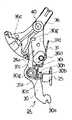
まず、図1を基に、ドアロック装置10(ドアロック装置)のラッチ機構の部分を説明する。ドアロック装置10は、ドア(図示なし)(車両ドア)に配設されるものであり、ラッチ11(ラッチ機構)及びポール12(ラッチ機構)を備えている。また、ラッチ11は収容溝11aを備えている。収容溝11aは車両ボデー(図示なし)に取り付けられたストライカ13(ストライカ)を、その内部に保持するものである。またポール12は当接部12aを有している。当接部12aはラッチ11と当接し、ラッチ11の図1示時計回り方向への回動を規制可能となっている。尚、ラッチ11とポール12はドアロック装置10の軸14、軸15に対して、一体的に回動可能に軸支されている。
【0023】
ここで、ドアロック装置10のラッチ機構の作動を説明する。図1は、ラッチ11がストライカ13と係合するラッチ状態を示している。このラッチ状態は、ドアが車両ボデーに対して保持された閉保持状態である。ラッチ状態からラッチ11が図1示時計回りに所定角度回動したアンラッチ状態では、ストライカ13が図1示左方向に離脱する。つまり、ラッチ11がストライカ13と非係合した状態となる。その結果、ドアは車両ボデーに対して開作動可能な状態となる。なお、ラッチ11は、軸14の周りに配設されたスプリング(図示なし)により図1示時計回り方向に付勢されている。つまり、ラッチ11の回動はそのスプリングの付勢力による。ここで、ポール12は前述の様に、ラッチ状態では当接部12aによりラッチ11の回動を抑えている。しかしながら、ポール12が図1示時計回り方向に所定角度分だけ回動すると、当接部12aとラッチ11の当接が外れ、ラッチ11はアンラッチ状態まで回動する。ポール12は、ラッチ11に対して当接状態から非当接状態となることによりラッチ11を作動させるものである。なお、ポール12も、軸15の周りに配設されたスプリング(図示なし)により、図1示反時計回り方向に付勢されている。
【0024】
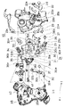
次に図2および図3を基にして、ドアロック装置10のロック機構の部分の説明をする。図2に示す様に、ドアロック装置10は、2枚のケース20a、20bから構成されるハウジング20に各部材が収容されている。図2は分解斜視図を、図3は、ケース部20a側に主要な部材を収容した状態を示す平面図である。
【0025】
ドアロック装置10のロック機構は、大まかに見て、オープン系操作部材と、ロック系操作部材とから構成されている。オープン系操作部材は、ドアの車両外側に配設される公知な構成のアウトサイドハンドル(開扉部材)(図示なし)や車両室内側に配設される公知な構成のインサイドハンドル(開扉部材・インサイドハンドル)(図示なし)の操作に基づいて、ラッチ11を作動させて、ドアを車両ボデーから開作動させる部材である。ロック系操作部材は、アウトサイドハンドル等の操作によってラッチ11の作動が可能なアンロック状態と作動が不可能なロック状態とを切替える部材である。
【0026】
オープン系部材は、アウトサイドオープンレバー21(オープンレバー)、第1インサイドオープンレバー22(オープンレバー)、第2インサイドオープンレバー23(オープンレバー)、オープン部材24(オープン部材)、リフトレバー25(リフトレバー)(図3示2点鎖線)、キャンセルレバー26(キャンセルレバー)から構成されている。
【0027】
アウトサイドオープンレバー21は、車両前後方向(図3示左右方向)に延在するの軸27に回動自在に軸支されている。その一端には、連結孔21aが形成されており、ロッド(図示なし)等を介してアウトサイドハンドルが連結している。また、他端側には略8字形状の連結孔21bが形成されている。そして、アウトサイドオープンレバー21はアウトサイドハンドルを操作すると、軸27を中心として回動する構成となっている。
【0028】
第1インサイドオープンレバー22は、ケース20bの車両幅方向室内側の面(ハウジング20外)にピン28にて回動自在に固定されている。第1インサイドオープンレバー22の一端には、連結切欠22aが形成されており、ケーブル(図示なし)等を介してインサイドハンドルが連結している。また、他端には、ケース20bに形成された円弧孔20c内に延在するフランジが形成されている。そして、インサイドオープンレバー22は、インサイドハンドルを操作すると、ピン28を中心として回動する構成となっている。
【0029】
第2インサイドオープンレバー23は、ケース20bの車両幅方向外側の面(ハウジング20内)にピン28にて回動自在に固定されている。第2インサイドオープンレバー23は、連結孔23aを備えている。連結孔23aには、前述の第1インサイドオープンレバー22のフランジが嵌合する。この部分にて、第1インサイドオープンレバー22から第2インサイドオープンレバーへトルクが伝達される。よって、両レバー22、23は一体的に回動する。また、第2インサイドオープンレバー23には、突起部23b、フランジ23cが形成されている。
【0030】
オープン部材24はオープンリンク30(リンク部材)とスプリング31(弾性部材)とから形成されている。オープンリンク30は剛性を有する金属性板状物であり、連結部30a(入力部)、ケース20bが位置する方向に屈曲形成され図3示上下方向に延びるフランジ30b(作用部)、図3示左右方向に延びるフランジ30c(入力部)、係止ピン30d、異形孔30e、ケース20aが位置する方向に屈曲形成されたフランジ30f等を備えている。連結部30aは、前述のアウトサイドオープンレバー21の連結孔21bに連結している。そして、この部分において、オープンレバー21からのトルク(操作力)が入力される。つまり、オープンレバー21が回動した場合には、オープンリンク30が連動して図3示上下方向に移動する。
【0031】
フランジ30bは、図3に示す様に、リフトレバー25の近傍に位置している。尚、リフトレバー25は、前述のポール12が軸支されている軸15に一体回動可能に軸支されており、リフトレバー25が図3示上方向に移動した場合には、ポール12が図1示時計回り方向に回動する様に構成されている。
【0032】
フランジ30cは、第2インサイドオープンレバー23が図3示反時計回り方向に回動したときに、突起部23bが係合するものである。つまり、該レバー23が回動したときには、突起部23bがフランジ30cと係合し、フランジ30cにトルク(操作力)が入力される。その結果、オープンリンク30は図3示上方向に移動しうる。
【0033】
係止ピン30dには、スプリング31が配設される。スプリング31は、その一端31aがオープンリンク30に支持されており、係止ピン30dを巻回してU字形状部31bが図3示上方向に延在している。そして、U字形状部31bの部分が係止ピン30d付近を中心として揺動する様に、撓変形可能となっている。
【0034】
キャンセルレバー26は、ピン29にて、ケース20bに回動自在に配設されており、突起部26aおよびフランジ26b(図2示)を備えている。突起部26aは、第2インサイドレバー23が図3示反時計回り方向に回動したときにフランジ23cが係合するものである。この構成により、係合した後には、第2インサイドレバー23とキャンセルレバー26は連動する。また、フランジ26bにはボス26cが配設されており、ボス26cはオープンリンク30の異形孔30eと連結している。
【0035】
ドアロック装置10のロック系操作部材は、インサイドロッキングレバー32(中間部材)、キーレバー33、モータ34、ホイルギア35、アクティブレバー36(ロックレバー)等から構成されている。インサイドロッキングレバー32は、ピン37によってケース30aの車両幅方向室内側(ハウジング30内)に回動可能に固定されている。そして、その一端には連結孔32aが形成されており、連結孔32aは、ケーブル(図示なし)等を介して、ドアの車両室内側に配設されるロックノブ(図示なし)に連結している。そして、ロックノブの操作によって、インサイドロッキングレバー32はピン37を中心として回動する。また、インサイドロッキングレバー32の他端側には、連結長孔32bが形成されており、また、ピン37と他端側との間にはケース20bが位置する方向に屈曲延在する屈曲フランジ32cが形成されている。この屈曲フランジ32cと前述のオープンリンク30のフランジ30fとは、係合可能な構成となっている。
【0036】
キーレバー33は、ロッド(図示なし)等を介して、ドアの車両外側に配設されるキーシリンダ(図示なし)に連結している。そして、キーシリンダがキー操作された場合に、回動する構成となっている。また、キーレバー33には連結切欠33aが形成されている。
【0037】
モータ34は、ドア若しくは車両ボデー内に配設されたECU(図示なし)によって作動するものである。このECUは、ドアの車両室内側に配設されるロックスイッチ(図示なし)の信号を受けて、モータ34に作動信号を送る。また、ECUは、アウトサイドハンドルに配設された静電容量センサが、人の手の接近を検知した信号を受けても、モータ34に作動信号を送信する構成となっている。尚、このECUが作動信号を送るための手段としては、これらの手段に限られない。ホイルギア35は軸38によって、ケース20aに回転自在に配設されており、モータ34の駆動に応じて回転する。また、ホイルギア35は、2本の連結ピン35aが形成されている。
【0038】
アクティブレバー36は略扇形状を呈しており、軸40上に揺動自在に配設されている。そして、アクティブレバー36は、ケース20a側に延在する連結ピン36a、節度ピン36e、ケース20b側に延在する連結ピン36b、36d、および連結凹部36cが形成されている。連結ピン36aはインサイドロッキングレバー32の連結長孔32bと連結しており、連結ピン36bはキーレバー33の連結切欠33aと連結している。また、ホイルギア35の回転によっては、2本の連結ピン35aが連結凹部36cと係脱する構成となっている。以上の構成によって、アクティブレバー36はインサイドロッキングレバー32、キーレバー33、モータ34からの操作によって、軸40を中心として揺動する。この揺動する際には、節度ピン36eがケース20aに固定された節度スプリング41内を移動する。そして、節度スプリング41の挟持形状と節度ピン36eの構成によって、アクティブレバー36が揺動する際の節度感が得られる。また、アクティブレバー36の連結ピン36dは、スプリング31のU字形状部31b内に位置しており、アクティブレバー36の揺動に伴って、オープン部材24全体(スプリング31とオープンリンク30)が連動する(連結部30a部分を中心として揺動する)。
【0039】
ここで、図4から図10に基づいてドアロック装置10の作動の説明をする。図4はドアロック装置10のアンロック状態を示している。アンロック状態では、オープン部材24は、オープンリンク30のフランジ30bがリフトレバー25の下側に位置する様なアンロック位置に位置している。また、このとき、アクティブレバー36もアンロック位置に位置している。この状態で、オープン操作されたときは、以下の様に作動する。アウトサイドハンドル等が操作されると、前述のアウトサイドオープンレバー21等を介して、オープン部材24全体が図4示上方向に移動する。そして、オープンリンク30のフランジ30bがリフトレバー25と図4示上方向(一方向)に係合する。ここで、リフトレバー25は上方向に作動可能となっており、その結果、ポール12、ラッチ11が作動する(アンラッチ状態となる)。その状態を図5に示した。このオープン部材24全体が移動する場合には、アクティブレバー36連結ピン36dがスプリング31のU字形状部31b内を相対的に移動する。
【0040】
次に、図4のアンロック状態でロック操作(ロック状態への切替え操作)がされたときは、以下の様に作動する。例えば、モータ34が作動した場合には、ホイルギア35を介して、アクティブレバー36が軸40を中心として図4示時計回り方向へ所定量回動する。この場合、連結軸36dを介してスプリング31へ回動力が伝達され、その結果、オープン部材24全体が、連結部30a部分を中心として図4示反時計回り方向へ所定量回動する。その状態を図6に示した。図6の状態では、アクティブレバー36、オープン部材24共にロック位置に位置する、ロック状態となっている。
【0041】
ロック状態にてアウトサイドハンドルを操作した場合(オープン操作した場合)には、オープン部材24全体が図6示略上方向に移動する。しかしながら、このときのフランジ30bの移動軌跡はリフトレバー25とオフセットしており、オープンリンク30は、リフトレバー25に対して空振りする。その状態を図7に示した。以上説明した様に、ロック状態でオープン操作された場合には、リフトレバー25が作動せず、アンラッチ状態とはならない。
【0042】
図7に示す状態にてアンロック操作(アンロック状態への切替え操作)がされたときには以下の様に作動する。例えば、モータ34が作動した場合には、ホイルギア35を介して、アクティブレバー36が軸40を中心として図7示反時計回り方向へ所定量回動する。この場合、連結軸36dがスプリング31の図7示右側部分に当接する。つまり、アクティブレバー36がロック位置からアンロック位置方向へ移動する場合に、アクティブレバー36がスプリング31の図7示右側部分に当接する構成となっている。その結果、オープン部材24全体が、連結部30a部分を中心として図7示時計回り方向へ所定量回動する。そして、フランジ30bがリフトレバー25に対して図7示右方向(他方向)に係合する。この方向は、リフトレバー25の作動が不可能な方向であるため、係合により、オープンリンク30の移動が規制される。しかしながら、アクティブレバー36の連結軸36dがスプリング31の図7示右側部分を更に右方向に押圧することにより、スプリング31は、係止ピン30d付近を中心として撓変形する。その結果、アクティブレバー36は、アンロック位置まで移動し得る。尚、本実施の形態では、節度スプリング41のスプリングトルクが、スプリング31のスプリングトルクよりも小さく設定されているため、アクティブレバー36がアンロック位置まで移動することができる。その状態を図8に示した。
【0043】
図8に示す状態からアウトサイドハンドルの操作を元に戻す(オープン操作を解除する)と、オープン部材24全体が図8示下方向に移動し、フランジ30bとリフトレバー25との係合が外れる。そして、スプリング31自身の付勢力によりオープンリンク30が連結部30aを中心として、所定量回動する。その結果、図4に示すアンロック状態となる。
【0044】
以上説明した様に、ロック状態において、アウトサイドハンドル等による操作およびモータ等によるの操作が重畳的に加わった場合であっても、アウトサイドハンドル等の操作を元に戻した場合はアンロック状態に切替わる。よって、再度のアンロック状態への切替え操作を行う必要が無く、操作の煩わしさが抑えられる。また、本実施の形態においては、この目的(操作の煩わしさの低減)は、オープンリンク30にスプリング31を配設することにより達成されており、部品点数が少なく、全体の構成が簡易なものとなっている。
【0045】
次に、本実施の形態において、図6示ロック状態からインサイドハンドルを操作した場合の作動を説明する。インサイドハンドルを操作した場合には、第1インサイドオープンレバー22および第2インサイドオープンレバー23を介してオープンリンク30のフランジ30cに操作力が入力される。その結果、オープン部材24全体が図6示略上方向に移動する。この作動と同時に、前述の様に、第2インサイドオープンレバー23はキャンセルレバー26を作動させる。その結果、キャンセルレバー26に配設されたボス26cと、異形孔30eを介して、オープンリンク30には、連結部30aを中心として図6示時計回り方向へ回動力が加えられる。更にこの場合、オープンリンク30のフランジ30fと屈曲フランジ32cが係合することにより、インサイドロッキングレバー32がピン37を中心として図6示時計回り方向に所定量回動する。そして、連結長孔32bおよび連結ピン36aを介して、アクティブレバー36が軸40を中心として図6示反時計回り方向へ回動する。その結果、図9に示す様に、オープンリンク30のフランジ30bは、リフトレバー25に対して図9示上方向に係合し得る構成となっている。そして、図5に示した様に、リフトレバー25を作動させることができ、ポール12、ラッチ11を作動させることができる(アンラッチ状態とすることができる)。以上説明した様に、ドアロック装置10は、ロック状態においてインサイドハンドルを一回操作した場合に、アンロック操作をするまでもなくドアを開けることが可能な構成(ワンモーション操作が可能な構成)となっている。尚、前述した様に、ワンモーション操作した場合には、インサイドロッキングレバー32が、リンク30のロック位置からアンロック位置方向への移動に基づいて、アクティブレバー36をロック位置からアンロック位置方向へ移動させる。つまり、オープン部材24のスプリング31を介してアクティブレバー36を移動させずに、剛性のあるインサイドロッキングレバー32を介してアクティブレバー36を移動させる構成としたため、その移動を確実に行うことができる。
【0046】
(第2の実施の形態)図10に基づいて第2の実施の形態を説明する。本実施の形態では、フランジ30bの図10示上下方向の長さが第1の実施の形態と比較して長く設定してある。それ以外の構成は第1の実施の形態と同じである。本実施の形態では、ロック状態からインサイドハンドルを一回操作した場合には、第1の実施の形態と同様に、第2インサイドオープンレバー23とキャンセルレバー26からの操作力によって、図10に示す状態となる。すなわち、オープンリンク30のフランジ30bが、リフトレバーに対して図10示右方向(他方向)に係合する様に構成されている。このときはリフトレバー25が作動しないため、一回の操作によっては、ポール12、ラッチ11を作動させることができない。しかしながら、第1の実施の形態と同様に、スプリング31が係止ピン30d付近を中心として撓変形することにより、アクティブレバー36は、アンロック位置まで移動し得る。そして、インサイドハンドルの操作を元に戻した場合には、フランジ30bとリフトレバー25との係合が外れ、図4に対応する様なアンロック状態となる。そして、再度インサイドハンドルを操作した場合には、ドアを開作動させることができる。以上説明した様に、本実施の形態のドアロック装置10は、ロック状態においてインサイドハンドルをニ回操作した場合に、アンロック操作をするまでもなくドアを開けることが可能な構成(ツーモーション操作が可能な構成)となっている。第1の実施の形態および第2の実施の形態から分かる様に、ドアロック装置10は、フランジ30bの長さを変えるだけで、簡易に、ワンモーション操作の機構とツーモーション操作の機構の何れをも設定することができる。
【0047】
(第3の実施の形態)図11から図15に基づいて第3の実施の形態を説明する。本実施の形態では、オープン部材24が第1の実施の形態と異なっている。本実施の形態では、オープン部材24が、図11等に示す様なオープンリンク30とスプリング31によって構成されている。オープンリンク30は、一端が、第1の実施の形態と同様に、アウトサイドオープンレバー21側に連結する連結部30aとなっており、他端が、アクティブレバー36側と当接する端部30gとなっている。端部30g側は、アクティブレバー36上に当接している。つまり、剛性のあるオープンリンク30が、アウトサイドオープンレバー21側とアクティブレバー36側に支持される構成となっている。従って、第1の実施の形態と比較して、オープン部材24全体の支持構成が安定なものとなっている。尚、オープンリンク30には、第1の実施の形態と同様にフランジ30b、フランジ30cを備えているが、それ以外にも、係止孔30h、抑えフランジ30i、ボス30jを備えている。
【0048】
スプリング31は、その一端31aが係止孔30hに係止されており、ボス30j周りにループ部31cが形成され、図11示上方向に延在している。その延在する途中は、抑えフランジ30iによって、図11示紙面手前方向への移動が抑えられており、他端31dは、フランジ30の端部30gに当接している。そして、スプリング31は、自身の付勢力によって、他端31dが端部30gと当接する方向へ付勢されている。以上の構成によって、オープン部材24は、オープンリンク30とスプリング31とによって挟まれる、連結部24aを備える構成となっている。この連結部24aは、図11示上下方向が長手方向となる形状となっており、連結部24aには、アクティブレバー36の連結ピン36dが嵌っている。
【0049】
ここで、図11から図15に基づいて作動の説明をする。図11は、アンロック状態を示している。アンロック状態では、オープン部材24、アクティブレバー36がアンロック位置に位置している。この状態で、オープン操作されたときは、オープン部材24全体が図11示上方向に移動する。そして、オープンリンク30のフランジ30bがリフトレバー25と上方向(一方向)に係合する。その結果、ポール12、ラッチ11が作動する(アンラッチ状態となる)。その状態を図12に示した。このオープン部材24全体が移動する場合には、アクティブレバー36連結ピン36dが、連結部24a内を相対的に移動する。
【0050】
次に、図11のアンロック状態でロック操作されたときは、アクティブレバー36が軸40を中心として図11示時計回り方向へ所定量回動する。この場合、連結軸36dがリンク30と当接する。つまり、アクティブレバー36がアンロック位置からロック位置方向に移動する方向にはリンク30が位置しており、アクティブレバー36がリンク30と当接する構成となっている。その結果、オープン部材24全体が、連結部30a部分を中心として図11示反時計回り方向へ所定量回動する。その状態を図13に示した。図13の状態では、アクティブレバー36、オープン部材24共にロック位置に位置する、ロック状態となっている。
【0051】
ロック状態にてアウトサイドハンドルを操作した場合(オープン操作した場合)には、オープン部材24全体が図13示略上方向に移動し、オープンリンク30は、リフトレバー25に対して空振りする。その状態を図14に示した。
【0052】
図14に示す状態にてアンロック操作(アンロック状態への切替え操作)がされたときには以下の様に作動する。アクティブレバー36が軸40を中心として図14示反時計回り方向へ所定量回動した場合、連結軸36dがスプリング31に当接する。つまり、アクティブレバー36がロック位置からアンロック位置方向へ移動する方向にはスプリング31が位置しており、アクティブレバー36がスプリング31と当接する構成となっている。その結果、オープン部材24全体が、連結部30a部分を中心として図14示時計回り方向へ所定量回動する。そして、フランジ30bがリフトレバー25に対して図14示右方向(他方向)に係合し、この係合により、オープンリンク30の移動が規制される。しかしながら、アクティブレバー36の連結軸36dがスプリング31を更に図14示右方向に押圧することにより、スプリング31は、ループ部31c付近を中心として撓変形する。その結果、アクティブレバー36は、アンロック位置まで移動し得る。尚、本実施の形態では、節度スプリング41のスプリングトルクが、スプリング31のスプリングトルクよりも小さく設定されているため、アクティブレバー36がアンロック位置まで移動することができる。その状態を図15に示した。
【0053】
図15に示す状態からアウトサイドハンドルの操作を元に戻す(オープン操作を解除する)と、オープン部材24全体が図15示下方向に移動し、フランジ30bとリフトレバー25との係合が外れる。そして、スプリング31自身の付勢力により、オープンリンク30が連結部30aを中心として、所定量回動する。その結果、図11に示すアンロック状態となる。
【0054】
以上説明した様に、ロック状態において、アウトサイドハンドル等による操作およびモータ等によるの操作が重畳的に加わった場合であっても、アウトサイドハンドル等の操作を元に戻した場合はアンロック状態に切替わる。よって、再度のアンロック状態への切替え操作を行う必要が無く、操作の煩わしさが抑えられる。また、本実施の形態においては、この目的(操作の煩わしさの低減)は、オープンリンク30にスプリング31を配設することにより達成されており、部品点数が少なく、全体の構成が簡易なものとなっている。
【0055】
尚、本実施の形態では、オープンリンク30に第1の実施の形態の異形孔30eに対応する孔を形成して、キャンセルレバー26のボス26cが連結する構成としても良い。その場合には、第1の実施の形態と同様に、ワンモーション操作の機構やツーモーション操作の機構を設定することができる。ここで、本実施の形態では、キャンセルレバー26によってオープン部材24全体がロック位置からアンロック位置方向に移動する場合、リンク30が連結ピン36dを直接押圧することにより、アクティブレバー36がロック位置からアンロック位置に移動させられる構成となっている。つまり、剛性のあるオープンリンク30がアクティブレバー36に当接しているため、オープン部材24の移動に基づいて、直接的にアクティブレバー36が移動させられるものとなっている。つまり、第1の実施の形態の様に、オープン部材24からインサイドロッキングレバー32を介してアクティブレバー36を動かす構成となっていないため、その構成は、より簡易なものとなっている。
【0056】
【発明の効果】
本発明は、ロック状態において、開扉部材、施解錠部材が重畳的に操作された場合であってもパニック状態とならず、アンロック状態への切替えを成立させることができる。従って、再度の施解錠部材の操作の必要がなく、操作の煩わしさを抑えることができる。また、オープン部材として、リンク部材と、リンク部材に対して弾性部材とを配設するのみで操作の煩わしさを抑えることができ、部品点数が少なく、全体の構造は簡易なものとなっている。
【0057】
本発明は、リンク部材の作用部の構成を変えることにより、ロック状態から、インサイドハンドルを一回若しくは二回操作することによって、車両ドアを車両ボデーに対して開作動可能とすることができる。換言すると、ロック状態からインサイドハンドルを何回操作すれば開作動するかを、リンク部材の作用部の構成を変えることにより、簡易に設定することができる。
【図面の簡単な説明】
【図1】 第1の実施の形態のドアロック装置の、ラッチ機構を表す平面図である。
【図2】 第1の実施の形態のドアロック装置の、ロック機構を表す分解斜視図である。
【図3】 第1の実施の形態のドアロック装置の、ロック機構を表す平面図である。
【図4】 第1の実施の形態のドアロック装置の、アンロック状態を表す図である。
【図5】 第1の実施の形態のドアロック装置の、アンロック状態においてオープン操作された状態を表す図である。
【図6】 第1の実施の形態のドアロック装置の、ロック状態を表す図である。
【図7】 第1の実施の形態のドアロック装置の、ロック状態においてオープン操作された状態を表す図である。
【図8】 図7示状態からアンロック状態への切替え操作がされた状態を表す図である。
【図9】 第1の実施の形態のドアロック装置の、ロック状態においてインサイドハンドルが操作された状態を表す図である。
【図10】 第2の実施の形態のドアロック装置の、ロック状態においてインサイドハンドルが操作された状態を表す図である。
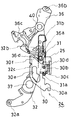
【図11】 第3の実施の形態のドアロック装置の、アンロック状態を表す図である。
【図12】 第3の実施の形態のドアロック装置の、アンロック状態においてオープン操作された状態を表す図である。
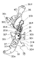
【図13】 第3の実施の形態のドアロック装置の、ロック状態を表す図である。
【図14】 第3の実施の形態のドアロック装置の、ロック状態においてオープン操作された状態を表す図である。
【図15】 図14示状態からアンロック状態への切替え操作がされた状態を表す図である。
【図16】 従来のドアロック装置を示す図である。
【符号の説明】
10 ドアロック装置
11 ラッチ(ラッチ機構)
12 ポール(ラッチ機構)
13 ストライカ
21 アウトサイドオープンレバー(オープンレバー)
22 第1インサイドオープンレバー(オープンレバー)
23 第2インサイドオープンレバー(オープンレバー)
24 オープン部材
25 リフトレバー
26 キャンセルレバー
30 オープンリンク(リンク部材)
30a 連結部(入力部)
30b フランジ(作用部)
30c フランジ(入力部)
31 スプリング(弾性部材)
32 インサイドロッキングレバー(中間部材)
36 アクティブレバー(ロックレバー)[0001]
BACKGROUND OF THE INVENTION
The present invention relates to a door lock device.
[0002]
[Prior art]
As a conventional door lock device, a latch mechanism that can be applied to a vehicle door and can be engaged with and disengaged from a striker on the vehicle body side, and a lift lever capable of operating the latch mechanism from an engaged state to an unengaged state with the striker An open lever that is operated by an operation of an opening member disposed on the vehicle door, and a lock lever that is movable between an unlock position and a lock position by an operation of a locking / unlocking member disposed on the vehicle door; In addition to being able to move between the unlocked position and the locked position in conjunction with the lock lever, and in the unlocked position, the lift lever and the one direction in which the lift lever can be operated by operation from the open lever When the lock lever is in the locked position, the lever is swung with respect to the lift lever by the operation from the open lever, and is unlocked from the lock position in the idle state. Those comprising an open member for engaging the lift lever and the lift lever in the other direction can not operate has become known when moving to the click position.
[0003]
In such a device, the case where the open member is in the unlocked position is referred to as an unlocked state, and the case where it is in the locked position is referred to as a locked state. In the unlocked state, the open member engages and operates with the lift lever by operating the door handle or the like, and as a result, the latch mechanism disengages from the striker. In the locked state, even if the door handle or the like is operated, the open member swings with respect to the lift lever, so that the lift lever does not operate. As a result, the latch mechanism cannot be disengaged from the striker.
[0004]
These devices are known to cause the following problems when the door handle or the like and the locking / unlocking member such as the lock knob are operated in a locked state. That is, when the door handle is operated earlier, the open member swings with respect to the lift lever and moves to the full stroke position in the locked state. Then, it moves from the full stroke position to the unlock position. At this time, since the open member engages with the lift lever in the other direction, a state in which the open member cannot move in the unlock position direction may occur. At this time, since the locking lever is also interlocked with the open member, a state where the locking lever cannot move in the unlock position direction may occur. Therefore, when the operation of the door handle is thereafter restored, the switch to the unlocked state remains unsatisfied even though the lock knob has been operated once (this state is referred to as a panic state). Therefore, in order to switch to the unlocked state, it is necessary to operate the lock knob again, and there is a problem that the operation is troublesome. In addition to this, there are other problems in door lock systems that automatically switch from the locked state to the unlocked state when a person approaches the door handle to operate the door handle. It can happen as well. This is because depending on the timing of control, manual door handle operation may be performed earlier than the automatic switching operation to the unlocked state.
[0005]
As a device for solving the above-mentioned problems, a device disclosed in Patent Document 1 described below is known. The configuration is shown in FIG. This device includes a
[0006]
This device operates as follows when the door handle and the lock knob are operated in a superimposed state in the locked state. First, the open member 93 moves in an approximately S direction in the figure while swinging with respect to the
[0007]
However, in this apparatus, since the
[0008]
[Patent Document 1]
JP-A-11-166337 (page 4, FIG. 7)
[0009]
[Problems to be solved by the invention]
An object of the present invention is to suppress the troublesome operation without complicating the structure of the door lock device.
[0010]
[Means for Solving the Problems]
The technical means taken in the present invention to solve the above-mentioned problems is applicable to a vehicle door and is capable of engaging and disengaging with a striker on the vehicle body side, and engaging the latch mechanism with the striker. Unlocked by operation of a lift lever operable from a state to a non-engaged state, an open lever operated by operation of an opening member disposed on the vehicle door, and an unlocking member disposed on the vehicle door A lock lever that can move between a position and a lock position, and can move between an unlock position and a lock position in conjunction with the lock lever.With open members,When the open member is in the unlocked positionRelative movement with respect to the lock lever by the operation of the open lever accompanying the operation of the door opening member,The lift leverAgainstWhen the lift lever is engaged in one operable direction and is in the locked position, the open leverOperationByWhile moving relative to the lock leverSwing to the lift lever,And the lift lever when moving from the locked position to the unlocked position in the idle stateAgainstA door lock device having an action part that engages the lift lever in the other direction incapable of being operated, wherein the open member has an input part to which an operating force is inputted from the open lever and a link member having the action part And when the lock lever moves at least from the lock position to the unlock position while being supported by the link member.On the lock leverContactThen, the movement of the lock lever to the unlock position is flexibly deformed in a state where the movement of the link member in the unlock direction is restricted by the action portion engaging with the lift lever in the other direction. AllowAn elastic member,The elastic member or the elastic member and the link member are configured to function also as a guide that allows the relative movement of the open member with respect to the lock lever by the operation of the open lever.
[0011]
According to this configuration, when the door opening member and the locking / unlocking member are operated in a superimposed manner in the locked state, the operation is as follows. First, the opening member is operated by operating the opening member.While moving relative to the lock leverSwing the lift lever. And the locking / unlocking member is operated in the idle state.When the lock lever moves from the lock position to the unlock position, even if the action portion engages with the lift lever in the other direction and the movement of the link member is restricted, the elastic member is bent and deformed to lock. The lever is allowed to move to the unlock position. Accordingly, when the operation state of the opening member is released in this state, the link member and the lift lever are disengaged, and the elastic member is restored by its own urging force, so that the entire open member is unlocked. Move to position.By the above operation,Door lock deviceSwitching from the locked state to the unlocked state is established. That is, with these configurations, even when the door opening member and the locking / unlocking member are operated in a superimposed manner in the locked state, the panic state is not established, and the switching to the unlocked state can be established. Therefore, it is not necessary to operate the locking / unlocking member again, and the troublesomeness of the operation can be suppressed.
[0012]
Further, in this configuration, as an open member, it is possible to suppress the troublesome operation only by disposing the link member and the elastic member with respect to the link member, the number of parts is small, and the entire structure is simple. It has become a thing.
[0013]
Preferably, the inside handle in which the opening member is disposed on the vehicle interior side of the vehicle door.IncludingWhen the inside handle is operated while the open member is in the locked position, the open member is moved to the unlocked position in conjunction with the open lever.With a cancel leverThe action part isWhen the open member is moved to the unlock position by the cancel leverIt may be configured to engage with the lift lever in the one direction.
[0014]
According to this configuration, even in the locked state, the lift lever can be operated by operating the inside handle once. That is, the open member is moved toward the unlock position by the cancel lever, and the action portion is engaged with the lift lever in one direction, so that the lift lever is operated. As a result, the latch mechanism can be operated so that the vehicle door can be opened with respect to the vehicle body.
[0015]
Preferably, an intermediate member that moves the lock lever from the lock position toward the unlock position based on the movement of the open member from the lock position toward the unlock position is preferably provided.
[0016]
According to this configuration, when the open member moves from the lock position toward the unlock position, the lock lever can also be moved to the unlock position via the intermediate member.
[0017]
Preferably, the elastic member extends in a direction of relative movement of the open member with respect to the lock lever, extends at a tip end thereof, and swings about a locking pin of the link member. It is preferable that the link pin is supported by the link member so as to be flexibly deformed, and a connecting pin of the lock lever is engaged between the extending portions of the elastic member so as to be relatively movable.
[0018]
Preferably, the elastic member extends in a direction of relative movement of the open member with respect to the lock lever, and is supported by the link member so as to be flexibly deformable so as to swing around a locking pin of the link member. The link member has a flange that extends in the relative direction and has a flange that is bent at a tip thereof and abuts against an end of the elastic member, and an extension portion of the elastic member and an extension portion of the link member, It is preferable that the connecting pin of the lock lever is engaged between the two so as to be relatively movable.
[0021]
DETAILED DESCRIPTION OF THE INVENTION
(First Embodiment) The first embodiment will be described with reference to FIGS. In each figure, the front direction of the vehicle is indicated by F, the vehicle width direction indoor direction is indicated by I, and the vehicle upward direction is indicated by U.
[0022]
First, the latch mechanism portion of the door lock device 10 (door lock device) will be described with reference to FIG. The
[0023]
Here, the operation of the latch mechanism of the
[0024]
Next, the part of the lock mechanism of the
[0025]
The lock mechanism of the
[0026]
The open members include an outside open lever 21 (open lever), a first inside open lever 22 (open lever), a second inside open lever 23 (open lever), an open member 24 (open member), and a lift lever 25 (lift) Lever) (two-dot chain line in FIG. 3) and cancel lever 26 (cancel lever).
[0027]
The outside
[0028]
The first inside
[0029]
The second inside
[0030]
The
[0031]
The
[0032]
The
[0033]
A
[0034]
The cancel
[0035]
The lock system operation member of the
[0036]
The
[0037]
The
[0038]
The
[0039]
Here, the operation of the
[0040]
Next, when a locking operation (switching operation to the locked state) is performed in the unlocked state of FIG. 4, the operation is as follows. For example, when the
[0041]
When the outside handle is operated in the locked state (when the opening operation is performed), the entire
[0042]
When an unlocking operation (switching operation to the unlocking state) is performed in the state shown in FIG. 7, the operation is as follows. For example, when the
[0043]
When the operation of the outside handle is returned from the state shown in FIG. 8 (open operation is released), the entire
[0044]
As described above, even when the operation by the outside handle or the like and the operation by the motor or the like are added in a superimposed state in the locked state, the operation is unlocked when the operation of the outside handle or the like is restored. Switch to. Therefore, it is not necessary to perform the switching operation to the unlocked state again, and the troublesomeness of the operation can be suppressed. Further, in the present embodiment, this object (reduction of troublesome operation) is achieved by disposing the
[0045]
Next, in the present embodiment, an operation when the inside handle is operated from the locked state shown in FIG. 6 will be described. When the inside handle is operated, an operating force is input to the
[0046]
(Second Embodiment) A second embodiment will be described with reference to FIG. In the present embodiment, the length of the
[0047]
(Third Embodiment) A third embodiment will be described with reference to FIGS. In the present embodiment, the
[0048]
One
[0049]
Here, the operation will be described with reference to FIGS. FIG. 11 shows the unlocked state. In the unlocked state, the
[0050]
Next, when the locking operation is performed in the unlocked state of FIG. 11, the
[0051]
When the outside handle is operated in the locked state (when the open handle is operated), the entire
[0052]
When the unlocking operation (switching operation to the unlocking state) is performed in the state shown in FIG. 14, the operation is as follows. When the
[0053]
When the operation of the outside handle is returned from the state shown in FIG. 15 (open operation is released), the entire
[0054]
As described above, even when the operation by the outside handle or the like and the operation by the motor or the like are added in a superimposed state in the locked state, the operation is unlocked when the operation of the outside handle or the like is restored. Switch to. Therefore, it is not necessary to perform the switching operation to the unlocked state again, and the troublesomeness of the operation can be suppressed. Further, in the present embodiment, this object (reduction of troublesome operation) is achieved by disposing the
[0055]
In this embodiment, the
[0056]
【The invention's effect】
In the locked state, even if the door opening member and the locking / unlocking member are operated in a superimposed manner, the present invention does not panic and can be switched to the unlocked state. Therefore, it is not necessary to operate the locking / unlocking member again, and the troublesomeness of the operation can be suppressed. In addition, as an open member, it is possible to suppress the troublesomeness of operation only by disposing a link member and an elastic member with respect to the link member, the number of parts is small, and the overall structure is simple. .
[0057]
In the present invention, by changing the configuration of the action portion of the link member, the vehicle door can be opened with respect to the vehicle body by operating the inside handle once or twice from the locked state. In other words, how many times the inside handle is operated from the locked state can be easily set by changing the configuration of the action portion of the link member.
[Brief description of the drawings]
FIG. 1 is a plan view illustrating a latch mechanism of a door lock device according to a first embodiment.
FIG. 2 is an exploded perspective view showing a lock mechanism of the door lock device of the first exemplary embodiment.
FIG. 3 is a plan view showing a lock mechanism of the door lock device of the first exemplary embodiment.
FIG. 4 is a diagram showing an unlocked state of the door lock device of the first exemplary embodiment.
FIG. 5 is a diagram illustrating a state in which the door lock device according to the first exemplary embodiment is opened in an unlocked state.
FIG. 6 is a diagram illustrating a locked state of the door lock device according to the first embodiment.
FIG. 7 is a diagram illustrating a state in which the door lock device according to the first exemplary embodiment is opened in the locked state.
8 is a diagram illustrating a state in which a switching operation from the state illustrated in FIG. 7 to the unlocked state has been performed.
FIG. 9 is a diagram illustrating a state in which the inside handle is operated in the locked state of the door lock device of the first exemplary embodiment.
FIG. 10 is a diagram illustrating a state in which the inside handle is operated in the locked state of the door lock device of the second exemplary embodiment.
FIG. 11 is a diagram illustrating an unlocked state of the door lock device of the third exemplary embodiment.
FIG. 12 is a diagram illustrating a state in which the door lock device according to the third exemplary embodiment is opened in an unlocked state.
FIG. 13 is a diagram showing a locked state of the door lock device of the third exemplary embodiment.
FIG. 14 is a diagram illustrating a state in which the door lock device according to the third exemplary embodiment is opened in a locked state.
15 is a diagram illustrating a state in which a switching operation from the state illustrated in FIG. 14 to the unlocked state has been performed.
FIG. 16 is a view showing a conventional door lock device.
[Explanation of symbols]
10 Door lock device
11 Latch (Latch mechanism)
12 pole (latch mechanism)
13 striker
21 Outside open lever (open lever)
22 1st Inside Open Lever (Open Lever)
23 Second inside open lever (open lever)
24 Open material
25 Lift lever
26 Cancel lever
30 Open link (link member)
30a Connecting part (input part)
30b Flange (action part)
30c Flange (input part)
31 Spring (elastic member)
32 Inside locking lever (intermediate member)
36 Active lever (lock lever)
Claims (5)
該ラッチ機構を前記ストライカとの係合状態から非係合状態へ作動可能なリフトレバーと、
前記車両ドアに配設された開扉部材の操作により作動するオープンレバーと、
前記車両ドアに配設された施解錠部材の操作によりアンロック位置とロック位置との間を移動可能なロックレバーと、
前記ロックレバーと連動してアンロック位置とロック位置との間を移動可能であるオープン部材とを備え、
該オープン部材は、アンロック位置にある場合には前記開扉部材の操作に伴う前記オープンレバーの作動により前記ロックレバーに対して相対移動して、前記リフトレバーに対し該リフトレバーを作動可能な一方向に係合し、ロック位置にある場合には前記オープンレバーの作動により前記ロックレバーに対して相対移動しつつ前記リフトレバーに対し空振りし、かつ空振り状態でロック位置からアンロック位置方向に移動した場合に前記リフトレバーに対し該リフトレバーを作動不可能な他方向に係合する作用部を有するドアロック装置であって、
前記オープン部材は、前記オープンレバーから操作力が入力される入力部及び前記作用部を有するリンク部材と、
該リンク部材に支持されるとともに前記ロックレバーが少なくともロック位置からアンロック位置方向に移動する場合に前記ロックレバーに当接し、前記作用部が前記リフトレバーと他方向に係合することにより前記リンク部材のアンロック方向への移動が規制された状態において、前記ロックレバーのアンロック位置までの移動を撓変形することで許容する弾性部材とを備え、
前記弾性部材又は、前記弾性部材及び前記リンク部材を、前記オープンレバーの作動による該オープン部材の前記ロックレバーに対する前記相対移動を許容するガイドとしても機能するよう構成したことを特徴とするドアロック装置。 A latch mechanism that is applicable to a vehicle door and that can be engaged with and disengaged from a striker on the vehicle body side;
A lift lever capable of operating the latch mechanism from the engaged state to the non-engaged state with the striker;
An open lever that is operated by an operation of an opening member disposed on the vehicle door;
A lock lever capable of moving between an unlock position and a lock position by operating a locking / unlocking member disposed on the vehicle door;
An open member that is movable between an unlock position and a lock position in conjunction with the lock lever ;
When the open member is in the unlock position, the open lever is moved relative to the lock lever by the operation of the open lever accompanying the operation of the opening member, and the lift lever can be operated with respect to the lift lever. When engaged in one direction and is in the locked position, the open lever is operated to swing relative to the lock lever while swinging relative to the lift lever , and from the locked position to the unlocked position while swinging. to the lift lever when moving a door lock device having an acting portion to be engaged in the other direction can not operate the lift lever,
The open member is a link member having an input portion to which an operating force is input from the open lever and the action portion;
Wherein by the locking lever while being supported by the link member is abutting on the lock lever when moving the unlock position direction from at least the locked position, the working portion is engaged with the lift lever and the other direction An elastic member that allows the movement of the lock lever to the unlock position by bending and deforming in a state where movement of the link member in the unlock direction is restricted ,
The door lock device characterized in that the elastic member or the elastic member and the link member function as a guide that allows the relative movement of the open member with respect to the lock lever by operation of the open lever. .
前記オープン部材がロック位置にある状態で前記インサイドハンドルが操作された場合に、前記オープンレバーと連動して前記オープン部材をアンロック位置へ移動させるキャンセルレバーを備え、
前記作用部は、前記オープン部材が前記キャンセルレバーによりアンロック位置に移動された際に前記リフトレバーと前記一方向に係合するように構成されることを特徴とする請求項1に記載のドアロック装置。 The opening member includes an inside handle disposed on the vehicle interior side of the vehicle door ;
A cancel lever that moves the open member to the unlock position in conjunction with the open lever when the inside handle is operated while the open member is in the lock position ;
The door according to claim 1, wherein the action portion is configured to engage with the lift lever in the one direction when the open member is moved to the unlocked position by the cancel lever. Locking device.
前記弾性部材の延在部位間に前記ロックレバーの有する連結ピンが相対移動自在に係合されることを特徴とする、請求項1〜3のいずれか一項に記載のドアロック装置。The door lock device according to any one of claims 1 to 3, wherein a connecting pin of the lock lever is engaged between extended portions of the elastic member so as to be relatively movable.
前記リンク部材は前記相対方向に延在し、かつその先端が屈曲して前記弾性部材の端部に当接するフランジを有し、The link member has a flange that extends in the relative direction and has a flange that is bent at its tip and abuts against an end of the elastic member;
前記弾性部材の延在部位と前記リンク部材の延在部位との間に前記ロックレバーの有する連結ピンが相対移動自在に係合されることを特徴とする、請求項1〜3のいずれか一項に記載のドアロック装置。4. The connection pin of the lock lever is engaged with the extension part of the elastic member and the extension part of the link member so as to be relatively movable. 5. The door lock device according to item.
Priority Applications (1)
| Application Number | Priority Date | Filing Date | Title |
|---|---|---|---|
| JP2002364040A JP4196665B2 (en) | 2002-07-29 | 2002-12-16 | Door lock device |
Applications Claiming Priority (2)
| Application Number | Priority Date | Filing Date | Title |
|---|---|---|---|
| JP2002219863 | 2002-07-29 | ||
| JP2002364040A JP4196665B2 (en) | 2002-07-29 | 2002-12-16 | Door lock device |
Publications (2)
| Publication Number | Publication Date |
|---|---|
| JP2004124687A JP2004124687A (en) | 2004-04-22 |
| JP4196665B2 true JP4196665B2 (en) | 2008-12-17 |
Family
ID=32300606
Family Applications (1)
| Application Number | Title | Priority Date | Filing Date |
|---|---|---|---|
| JP2002364040A Expired - Fee Related JP4196665B2 (en) | 2002-07-29 | 2002-12-16 | Door lock device |
Country Status (1)
| Country | Link |
|---|---|
| JP (1) | JP4196665B2 (en) |
Families Citing this family (6)
| Publication number | Priority date | Publication date | Assignee | Title |
|---|---|---|---|---|
| JP4659602B2 (en) * | 2005-11-30 | 2011-03-30 | 三井金属アクト株式会社 | Control device for vehicle door latch |
| JP4775345B2 (en) | 2007-08-24 | 2011-09-21 | アイシン精機株式会社 | Vehicle door lock device |
| JP5108476B2 (en) * | 2007-11-22 | 2012-12-26 | アイシン精機株式会社 | Vehicle door lock device |
| JP4952752B2 (en) * | 2009-07-27 | 2012-06-13 | アイシン精機株式会社 | Vehicle door lock device |
| JP5129854B2 (en) * | 2010-11-05 | 2013-01-30 | 三井金属アクト株式会社 | Control device for vehicle door latch |
| JP6989076B2 (en) * | 2019-03-04 | 2022-01-05 | 三井金属アクト株式会社 | Automotive door latch device |
-
2002
- 2002-12-16 JP JP2002364040A patent/JP4196665B2/en not_active Expired - Fee Related
Also Published As
| Publication number | Publication date |
|---|---|
| JP2004124687A (en) | 2004-04-22 |
Similar Documents
| Publication | Publication Date | Title |
|---|---|---|
| JP4196617B2 (en) | Door lock device | |
| US7399010B2 (en) | Power-actuated motor-vehicle door latch with quick unlock | |
| JP3324223B2 (en) | Door lock device | |
| US6655179B2 (en) | Automotive door lock assembly | |
| JP2816796B2 (en) | Vehicle door lock device with idle swing type super lock mechanism | |
| US6045168A (en) | Door latch with improved double lock | |
| JP2000303731A (en) | Vehicle door latch device with double action mechanism | |
| US7438331B2 (en) | Apparatus for opening and closing door | |
| JP2000345751A (en) | Vehicle door latch device with block type anti-theft mechanism | |
| JP4165176B2 (en) | Door lock device | |
| US7390034B2 (en) | Latch apparatus | |
| JP4196665B2 (en) | Door lock device | |
| GB2284636A (en) | Vehicle door locking device with an antitheft mechanism | |
| JP2004244993A (en) | Door lock device | |
| JP3310964B2 (en) | Vehicle door latch device with double action mechanism and anti-theft mechanism | |
| JP2001271531A (en) | Door lock device for automobile | |
| US20220065005A1 (en) | Door latch device | |
| JP4196258B2 (en) | Door lock device | |
| JP2001248347A (en) | Door lock device for automobile | |
| JPH061021B2 (en) | Opening and closing device for vehicle doors | |
| JPH08270290A (en) | Door lock device | |
| JPH0735707B2 (en) | Opening and closing device for vehicle doors | |
| JP2023154186A (en) | outside handle device | |
| JP2000274129A (en) | Slide door lock device for construction machine | |
| JP2004027509A (en) | Door lock device |
Legal Events
| Date | Code | Title | Description |
|---|---|---|---|
| A621 | Written request for application examination |
Free format text: JAPANESE INTERMEDIATE CODE: A621 Effective date: 20051125 |
|
| A977 | Report on retrieval |
Free format text: JAPANESE INTERMEDIATE CODE: A971007 Effective date: 20080409 |
|
| A131 | Notification of reasons for refusal |
Free format text: JAPANESE INTERMEDIATE CODE: A131 Effective date: 20080603 |
|
| A521 | Written amendment |
Free format text: JAPANESE INTERMEDIATE CODE: A523 Effective date: 20080728 |
|
| TRDD | Decision of grant or rejection written | ||
| A01 | Written decision to grant a patent or to grant a registration (utility model) |
Free format text: JAPANESE INTERMEDIATE CODE: A01 Effective date: 20080909 |
|
| A01 | Written decision to grant a patent or to grant a registration (utility model) |
Free format text: JAPANESE INTERMEDIATE CODE: A01 |
|
| A61 | First payment of annual fees (during grant procedure) |
Free format text: JAPANESE INTERMEDIATE CODE: A61 Effective date: 20080922 |
|
| FPAY | Renewal fee payment (event date is renewal date of database) |
Free format text: PAYMENT UNTIL: 20111010 Year of fee payment: 3 |
|
| R151 | Written notification of patent or utility model registration |
Ref document number: 4196665 Country of ref document: JP Free format text: JAPANESE INTERMEDIATE CODE: R151 |
|
| FPAY | Renewal fee payment (event date is renewal date of database) |
Free format text: PAYMENT UNTIL: 20111010 Year of fee payment: 3 |
|
| FPAY | Renewal fee payment (event date is renewal date of database) |
Free format text: PAYMENT UNTIL: 20121010 Year of fee payment: 4 |
|
| FPAY | Renewal fee payment (event date is renewal date of database) |
Free format text: PAYMENT UNTIL: 20121010 Year of fee payment: 4 |
|
| FPAY | Renewal fee payment (event date is renewal date of database) |
Free format text: PAYMENT UNTIL: 20131010 Year of fee payment: 5 |
|
| LAPS | Cancellation because of no payment of annual fees |