JP4198768B2 - Door frame - Google Patents
Door frame Download PDFInfo
- Publication number
- JP4198768B2 JP4198768B2 JP11990497A JP11990497A JP4198768B2 JP 4198768 B2 JP4198768 B2 JP 4198768B2 JP 11990497 A JP11990497 A JP 11990497A JP 11990497 A JP11990497 A JP 11990497A JP 4198768 B2 JP4198768 B2 JP 4198768B2
- Authority
- JP
- Japan
- Prior art keywords
- tongue
- frame
- slot
- door
- door frame
- Prior art date
- Legal status (The legal status is an assumption and is not a legal conclusion. Google has not performed a legal analysis and makes no representation as to the accuracy of the status listed.)
- Expired - Lifetime
Links
- 230000007423 decrease Effects 0.000 claims description 2
- 238000005452 bending Methods 0.000 claims 1
- 210000002105 tongue Anatomy 0.000 description 34
- 238000010586 diagram Methods 0.000 description 6
- 238000004519 manufacturing process Methods 0.000 description 2
- 238000012986 modification Methods 0.000 description 2
- 230000004048 modification Effects 0.000 description 2
- 241000283973 Oryctolagus cuniculus Species 0.000 description 1
- 238000000034 method Methods 0.000 description 1
- 238000004080 punching Methods 0.000 description 1
- 238000003466 welding Methods 0.000 description 1
Images


Classifications
-
- E—FIXED CONSTRUCTIONS
- E06—DOORS, WINDOWS, SHUTTERS, OR ROLLER BLINDS IN GENERAL; LADDERS
- E06B—FIXED OR MOVABLE CLOSURES FOR OPENINGS IN BUILDINGS, VEHICLES, FENCES OR LIKE ENCLOSURES IN GENERAL, e.g. DOORS, WINDOWS, BLINDS, GATES
- E06B3/00—Window sashes, door leaves, or like elements for closing wall or like openings; Layout of fixed or moving closures, e.g. windows in wall or like openings; Features of rigidly-mounted outer frames relating to the mounting of wing frames
- E06B3/96—Corner joints or edge joints for windows, doors, or the like frames or wings
- E06B3/988—Corner joints or edge joints for windows, doors, or the like frames or wings specially adapted for sheet metal frame members with an open U-shaped cross-section
Landscapes
- Engineering & Computer Science (AREA)
- Civil Engineering (AREA)
- Structural Engineering (AREA)
- Joining Of Corner Units Of Frames Or Wings (AREA)
- Elevator Door Apparatuses (AREA)
- Door And Window Frames Mounted To Openings (AREA)
- Wing Frames And Configurations (AREA)
- Supports Or Holders For Household Use (AREA)
Description
【0001】
【発明の属する技術分野】
本発明は、接続手段を用いて接続可能なフレーム要素から成るドアフレームに関する。
【0002】
【従来の技術】
接続ブラケットを用いて着脱可能に接続されるドア用フレーム要素が、特許明細書WO95/32912に開示されている。ドアポスト2本およびトランサム(transom)要素で、ドアフレームが形成される。L字形状の接続ブラケットの長尺リム(long limb)には孔があり、短尺リム(short limb)には延長スロット(elongate slot)がある。接続ブラケットの長尺リムは、別の接続ブラケットにネジで接続され、この別の接続ブラケットはドアポストに接続されて、ドアポスト(door post)の剛性を高める。トランサム要素にはドアドライブが配設されており、トランサム要素は、接続ブラケットの長尺リムおよび短尺リムにネジで接続される。延長スロットを備えた別の接続ブラケットは、フレーム構造を壁に固定する手段となり、短尺リムにネジ止めされる。
【0003】
【発明が解決しようとする課題】
製造コストが高く、組み立てが面倒な接続ブラケットが、フレーム要素の接続に必要なこと、また、接続手段となるネジやナットが緩み、そのため、例えばエレベータ用ドアのフレームなどの場合に重大な結果を招くことが前記ドアフレームの問題点である。
【0004】
【課題を解決するための手段】
本発明は、前記の問題点を解消するものである。本発明は、接続手段によって接続可能なフレーム要素1、2、3から成るドアフレームであって、前記接続手段が前記フレーム要素1、2、3の構成要素であることを特徴とするドアフレームであり、前記既知のドアフレームの問題点を解決するという目的を満たすとともに、一旦接続すると分離不可能となる差し込み可能なフレーム要素を備えたドアフレームを提供するものである。
【0005】
本発明の主な特徴は、溶接、ネジ止め、リベット止めなど、コストのかかる組み立て作業が不必要であり、したがって、組み立てコストを実質的に節減できる点にある。また、固定金具を備えた一体型のフレーム要素を機械的に製造できるため、本発明によるドアフレームは、従来の接続手段に必要である組み立てゲージを使用しなくても正確に組み立てることができる。接続方法が単純であることから、本発明のドアフレームは軽量であり、分解して輸送した後、現場で組み立てることができる。
【0006】
以下、一実施の形態についてのみ図示した図面を参照して、本発明につき詳細に説明する。
【0007】
【発明の実施の形態】
図1から図11に、フレーム要素四つから成るドアフレームを示す。図において、底部の敷居要素(threshold element)1、各側それぞれ一つずつのドアポスト2、および上部のまぐさ要素(lintel element)3が、フレーム要素として設けられ、ドアポスト2は、敷居要素1の上に立ち、まぐさ要素3は、ドアポスト2の間に配設されている。
【0008】
図1から図4において、敷居要素1は、基部4、第1の長手方向側部6の第1のカラー(collar)5、および第2の長手方向側部8の第2のカラー7を備え、U字形の断面形状をしている。ドアポスト2は、L字形状であって、第1のリム9の位置に第3のカラー10を備え、また第2のリム11の位置に第4のカラー12を備えている。敷居要素1、ドアポスト2、およびまぐさ要素3にある組み立てに必要な開口部であるリセスには、参照番号13を付してある。第1のトング(tongue)すなわち舌状突部14は、ドアポスト2の第3のカラー10に配設され、第2のトング15は、ドアポスト2の第2のリム11に配設されている。第1のリム9および第2のリム11によって形成される、ドアポスト2のコーナには、敷居要素1の第1の長手方向側部6の高さに切り込み16が設けられている。敷居要素1の基部4には、第1のスロット17があり、第2のカラー7には、第2のスロット18がある。第1の長手方向側部6の第1のカラー5は、ドアポスト2の第1のリム9の幅に相当するだけ切り取られている。
【0009】
組み立て時に、第1のトング14を第1のスロット17に差し込み、第2のトング15を第2のスロット18に差し込むと、ドアポスト2の第1のリム9は、第1のカラー5の切り込み領域で、敷居要素1の長手方向側部6の裏側と係合する。次に図3および図4に示すように第1のトング14と第2のトング15とを変形させ、これにより敷居要素1は、ドアポスト2と機械的に確実にかつ分離不可能に接続される。
【0010】
図5および図6に、敷居要素1とドアポスト2との別の接続例を示す。第1のリム9は、第1のダブルトング(double tongue)19を備え、ドアポスト2の第2のリム11は、第2のダブルトング20を備えている。第1のダブルトング19に嵌合する第1のリセス(recess)21は、敷居要素1の第1の長手方向側部6に配設されている。敷居要素1の基部4から打ち抜かれた第1のブラケット(bracket)22は、第2のダブルトング20に嵌合する第2のリセス23を備えている。組み立て時、図6に示すようにダブルトング19および20をリセス21および23に差し込んで変形させると、敷居要素1は、ドアポスト2と機械的に確実にかつ分離不可能に接続される。
【0011】
敷居要素1とドアポスト2とのさらに別の接続例では、図1から図4の接続例を、図5および図6の接続例と組み合わせている。
【0012】
図7から図9に、ドアポスト2をまぐさ要素3と接続する実施の形態を示す。U字形状のまぐさ要素3は、第3のカラー25を備えた第3の長手方向側部24と、第4のカラー27を備えた第4の長手方向側部26を有している。第3の長手方向側部24の端部には、第3のスロット29を備えた第3のトング28と、第4のスロット31を備えた第4のトング30とがある。また、第4の長手方向側部26の端部には、第5のスロット33を備えた第5のトング32と、第6のスロット35を備えた第6のトング34とがある。そして、第4のカラー27の端部には、第7のトング36がある。
【0013】
ドアポスト2のまぐさ側端部には、第7のスロット37、第8のスロット38、第9のスロット39、第10のスロット40、および第11のスロット41があり、この端部で第7のスロット37は第3のトング28に嵌合し、第8のスロット38は第4のトング30に嵌合し、第9のスロット39は第5のトング32に嵌合し、第10のスロット40は第6のトング34に嵌合し、第11のスロット41は第7のトング36に嵌合する。
【0014】
追加要素45の第8のトング44を備えた第4のリセス43に嵌合する第3のリセス42は、ドアポスト2の位置に配設されている。第9のトング47を備えた第5のリセス46、第10のトング49を備えた第6のリセス48、第11のトング50、および第12のトング51は、追加要素45に配設され、ここで前記のトングおよびスロットは、まぐさ要素3のトングおよびスロットに嵌合する。
【0015】
組み立て時、まぐさ要素3のトングをドアポスト2のスロットに差し込み、追加要素45をドアポスト端部でまぐさ要素3のトングに対して押圧する。図8および図9に示すように、まぐさ要素3のトングは、ドアポスト2のスロット37、38、39、および40から突出する。次に、追加要素45を下方に移動すると、追加要素45のトング47、49、50、および51は、まぐさ要素3のスロット29、31、33、および35に嵌合する。第8のトング44が、ドアポスト2の第3のリセス42の内部に曲がり込むため、このトングにより、追加要素45の上方への動きが防止される。第7のトング36は、ドアポスト端部で変形させる。ドアポスト2とまぐさ要素3との差し込み式接続は、機械的に確実であり、分離不可能である。
【0016】
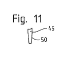
図10は、追加要素45のトング50を示す図である。トング50の幅は、その自由端部に向かって減少する。すなわち、トング50は、わずかに楔形状になっている。打抜き工具を用いて平らにすることにより、図11に示すごとく、厚さがわずかに楔形状になるようにトング50の自由端部を成形することも可能である。追加要素45のその他のトング44、47、49、および51は、トング50と同様に作られている。トング44、47、49、50、および51は、幅または厚さあるいはその両方が楔形状になっているため、スロット29、31、22、35、および42に容易に差し込むことができる。楔形状のトング44、47、49、50、および51については、製造公差の補償が可能である。
【図面の簡単な説明】
【図1】接続する二つのフレーム要素を示す図である。
【図2】相互に接続した図1の二つのフレーム要素を示す図である。
【図3】図2の接続したフレーム要素の詳細を示す図である。
【図4】図2の接続したフレーム要素の詳細を示す図である。
【図5】接続するフレーム要素の実施の形態の変形例を示す図である。
【図6】相互に接続した図5の二つのフレーム要素を示す図である。
【図7】接続するフレーム要素の実施の形態の別の変形例を示す図である。
【図8】さらに別の要素と接続した図7の二つのフレーム要素を示す図である。
【図9】図8の別の要素により固定した二つのフレーム要素を示す図である。
【図10】別の要素のトングの平面図である。
【図11】図10のトングの側面図である。
【符号の説明】
1 敷居要素
2 ドアポスト
3 まぐさ要素
21、23、42 リセス
28、30、32、34、44、47、49、50、51 トング
29、31、33、35、37、38、39、40 スロット
45 追加要素[0001]
BACKGROUND OF THE INVENTION
The present invention relates to a door frame comprising a frame element that can be connected using connecting means.
[0002]
[Prior art]
A door frame element that is detachably connected using a connection bracket is disclosed in the patent specification WO 95/32912. A door frame is formed by two door posts and a transom element. The long limb of the L-shaped connection bracket has a hole, and the short limb has an elongated slot. The long rim of the connection bracket is screwed to another connection bracket, which is connected to the door post to increase the rigidity of the door post. A door drive is disposed on the transom element, and the transom element is connected to the long rim and the short rim of the connection bracket with screws. Another connecting bracket with an extension slot provides a means for securing the frame structure to the wall and is screwed to the short rim.
[0003]
[Problems to be solved by the invention]
Connection brackets that are expensive to manufacture and cumbersome to assemble are necessary to connect the frame elements, and the screws and nuts that make the connection are loosened, which can cause serious consequences, for example, in elevator door frames. Inviting is a problem of the door frame.
[0004]
[Means for Solving the Problems]
The present invention solves the above problems. The present invention provides a door frame comprising
[0005]
The main feature of the present invention is that costly assembly operations such as welding, screwing, and riveting are unnecessary, and therefore assembly costs can be substantially reduced. In addition, since the integrated frame element having the fixing bracket can be mechanically manufactured, the door frame according to the present invention can be accurately assembled without using an assembly gauge required for the conventional connecting means. Since the connection method is simple, the door frame of the present invention is lightweight and can be assembled on site after being disassembled and transported.
[0006]
Hereinafter, the present invention will be described in detail with reference to the drawings illustrating only one embodiment.
[0007]
DETAILED DESCRIPTION OF THE INVENTION
1 to 11 show a door frame comprising four frame elements. In the figure, a
[0008]
1 to 4, the
[0009]
During assembly, when the
[0010]
5 and 6 show another example of connection between the
[0011]
In yet another connection example between the
[0012]
7 to 9 show an embodiment in which the
[0013]
The lintel side end of the
[0014]
A
[0015]
During assembly, the tongue of the
[0016]
FIG. 10 is a diagram showing the
[Brief description of the drawings]
FIG. 1 is a diagram showing two frame elements to be connected.
FIG. 2 shows the two frame elements of FIG. 1 connected to each other.
FIG. 3 is a diagram showing details of the connected frame elements of FIG. 2;
FIG. 4 is a diagram showing details of connected frame elements of FIG. 2;
FIG. 5 is a diagram showing a modification of the embodiment of the frame element to be connected.
6 shows the two frame elements of FIG. 5 connected to each other.
FIG. 7 is a diagram showing another modification of the embodiment of the frame element to be connected.
8 shows the two frame elements of FIG. 7 connected to yet another element.
FIG. 9 shows two frame elements fixed by another element of FIG.
FIG. 10 is a plan view of a tongue of another element.
11 is a side view of the tongue of FIG.
[Explanation of symbols]
1
Claims (3)
第1のフレーム要素(3)の各舌状突部(28、30、32、34)が、追加要素(45)の舌状突部(47、49、50、51)が嵌合されるスロット(29、31、33、35)を有しており、
追加要素(45)は、板状であって、舌状突部(47、49、50、51)を備えた開口部(46、48)を有しており、
第1のフレーム要素(3)を第2のフレーム要素(2)に差し込んだ後、板状の追加要素(45)を第2のフレーム要素端部において第1のフレーム要素(3)の舌状突部(28、30、32、34)に対して押圧してから下方に移動させることにより、この追加要素の舌状突部(47、49、50、51)が、第1のフレーム要素(3)の舌状突部(28、30、32、34)のスロット(29、31、33、35)内に保持されることを特徴とするドアフレーム。The first frame element (3) in the horizontal direction and the second frame element (2) in the vertical direction, which are connected by using the connection means, are provided as connection means on the first frame element (3). A door frame in which a plurality of tongue-like protrusions (28, 30, 32, 34) are inserted into slots (37, 38, 39, 40) of the second frame element (2),
Each tongue projection of the first frame element (3) (28, 30, 32, 34) are tongue-shaped protrusions (47,49,50,51) is fitted in the additional element (45) Slot (29, 31, 33, 35),
The additional element (45) is plate-shaped and has openings (46, 48) with tongue-like protrusions (47, 49, 50, 51),
After inserting the first frame element (3) into the second frame element (2), the plate-like additional element (45) is tongued out of the first frame element (3) at the end of the second frame element. By pressing against the protrusions (28, 30, 32, 34) and then moving downwards, the tongue-like protrusions (47, 49, 50, 51) of this additional element become the first frame elements ( 3) A door frame which is held in the slot (29, 31, 33, 35) of the tongue-like protrusion (28, 30, 32, 34) of 3).
Applications Claiming Priority (2)
| Application Number | Priority Date | Filing Date | Title |
|---|---|---|---|
| CH96810300.2 | 1996-05-13 | ||
| EP96810300 | 1996-05-13 |
Publications (2)
| Publication Number | Publication Date |
|---|---|
| JPH1061340A JPH1061340A (en) | 1998-03-03 |
| JP4198768B2 true JP4198768B2 (en) | 2008-12-17 |
Family
ID=8225605
Family Applications (1)
| Application Number | Title | Priority Date | Filing Date |
|---|---|---|---|
| JP11990497A Expired - Lifetime JP4198768B2 (en) | 1996-05-13 | 1997-05-09 | Door frame |
Country Status (10)
| Country | Link |
|---|---|
| US (1) | US6041565A (en) |
| JP (1) | JP4198768B2 (en) |
| CN (1) | CN1076069C (en) |
| AR (1) | AR007114A1 (en) |
| AT (1) | ATE256245T1 (en) |
| BR (1) | BR9703129A (en) |
| CA (1) | CA2205164C (en) |
| CZ (1) | CZ295842B6 (en) |
| DE (1) | DE59711090D1 (en) |
| ES (1) | ES2212012T3 (en) |
Families Citing this family (10)
| Publication number | Priority date | Publication date | Assignee | Title |
|---|---|---|---|---|
| AUPN967096A0 (en) * | 1996-05-06 | 1996-05-30 | Beaton, Ross | Door frames |
| CA2266358A1 (en) * | 1998-03-23 | 1999-09-23 | Ingersoll-Rand Company | Door frame for metal buildings |
| US7333794B2 (en) * | 2001-03-06 | 2008-02-19 | At&T Mobility Ii Llc | Real-time network analysis and performance management |
| AU2007202762B2 (en) * | 2006-09-18 | 2013-10-03 | Capral Limited | Interconnection of a mullion with a window frame or door frame |
| EP2019074A1 (en) * | 2007-07-26 | 2009-01-28 | Macpuar, S.A. | Automatic elevator door and method of assembling it |
| AU2008100058B4 (en) * | 2008-01-18 | 2011-10-13 | Jds Metal Doorframe Manufacture Pty Ltd | Improved Joining System for Metal Door Frames |
| EP2857623A1 (en) * | 2013-10-02 | 2015-04-08 | Masonite Corporation | Doorset installation comprising an opening frame, and method for assembling the doorset installation in a bay of a wall |
| CN103670142A (en) * | 2013-12-10 | 2014-03-26 | 南乐广安金属门业制造有限公司 | Assembling door frame |
| CN103628777B (en) * | 2013-12-11 | 2015-08-26 | 合肥美的电冰箱有限公司 | Doorframe and there is its door body of chiller plant |
| JP2016069135A (en) * | 2014-09-30 | 2016-05-09 | 株式会社日立製作所 | Jamb of elevator device, elevator device using the same and jamb assembling method for elevator device |
Family Cites Families (12)
| Publication number | Priority date | Publication date | Assignee | Title |
|---|---|---|---|---|
| US1327441A (en) * | 1916-07-07 | 1920-01-06 | Mesker Brothers Iron Company | Metallic window construction |
| GB556752A (en) * | 1942-04-16 | 1943-10-20 | George Charles Wright | Improvements in metal door and like frames for buildings |
| US2741344A (en) * | 1953-03-02 | 1956-04-10 | American Welding And Mfg Compa | Knock-down metal door frame |
| AU812166A (en) * | 1967-07-11 | 1969-01-10 | Wormald Brothers Industries Limited | An improved frame for the door jambs of a firedoor |
| US3769773A (en) * | 1972-06-05 | 1973-11-06 | M Mochizuki | Collapsible door-fitting frame |
| DE2548003A1 (en) * | 1975-10-27 | 1977-04-28 | Graf Gmbh | Door case profile corner connection - has slits on lugs engaged by clamping unit between lugs |
| US4021988A (en) * | 1976-06-16 | 1977-05-10 | National Manufacturing Company | Metal frame construction |
| NL7903171A (en) * | 1979-04-23 | 1980-10-27 | Metaal En Kunststofindustrie B | MASONRY FRAME. |
| DE2924442C2 (en) * | 1979-06-18 | 1982-10-14 | Georg 5950 Finnentrop Stuff | Frame for windows or doors |
| SE8202633L (en) * | 1982-04-28 | 1983-10-29 | Hellbergs Ind Ab | DEVICE AT KARM |
| IT235086Y1 (en) * | 1994-05-31 | 2000-03-31 | Selcom Spa | CONNECTION ELEMENT AND MULTI-FUNCTIONAL SUPPORT IN AUTOMATIC DOOR HANDLING MECHANISM FOR LIFTS AND ELEVATORS |
| US5581953A (en) * | 1995-05-31 | 1996-12-10 | Ingersoll-Rand | Metal frame assembly |
-
1997
- 1997-05-03 DE DE59711090T patent/DE59711090D1/en not_active Expired - Lifetime
- 1997-05-03 AT AT97107330T patent/ATE256245T1/en active
- 1997-05-03 ES ES97107330T patent/ES2212012T3/en not_active Expired - Lifetime
- 1997-05-09 JP JP11990497A patent/JP4198768B2/en not_active Expired - Lifetime
- 1997-05-12 BR BR9703129A patent/BR9703129A/en not_active IP Right Cessation
- 1997-05-12 CZ CZ19971439A patent/CZ295842B6/en not_active IP Right Cessation
- 1997-05-12 CN CN97111183A patent/CN1076069C/en not_active Expired - Fee Related
- 1997-05-12 CA CA002205164A patent/CA2205164C/en not_active Expired - Fee Related
- 1997-05-13 AR ARP970101997A patent/AR007114A1/en unknown
- 1997-05-13 US US08/855,194 patent/US6041565A/en not_active Expired - Lifetime
Also Published As
| Publication number | Publication date |
|---|---|
| US6041565A (en) | 2000-03-28 |
| JPH1061340A (en) | 1998-03-03 |
| CZ295842B6 (en) | 2005-11-16 |
| MX9703383A (en) | 1998-06-30 |
| AR007114A1 (en) | 1999-10-13 |
| CZ143997A3 (en) | 1997-12-17 |
| CA2205164C (en) | 2005-08-23 |
| DE59711090D1 (en) | 2004-01-22 |
| ES2212012T3 (en) | 2004-07-16 |
| ATE256245T1 (en) | 2003-12-15 |
| CA2205164A1 (en) | 1997-11-12 |
| CN1167202A (en) | 1997-12-10 |
| BR9703129A (en) | 1998-09-22 |
| CN1076069C (en) | 2001-12-12 |
Similar Documents
| Publication | Publication Date | Title |
|---|---|---|
| US7918065B2 (en) | Fastening member and external wall construction structure using the same | |
| US20040088943A1 (en) | Plug connector for hollow sections | |
| CN102037195B (en) | Building assembly structure, and building assembly method using the same | |
| JP3867719B2 (en) | Fastening member, outer wall construction structure and outer wall construction method using the same | |
| US6325349B1 (en) | Self-leveling window bracket | |
| JPH1061340A (en) | Door frame | |
| KR20100103168A (en) | Module unit for modular building | |
| KR200354388Y1 (en) | Sandwich panels and wall fabricated using them | |
| JP3188632B2 (en) | Frame assembly equipment | |
| KR200163581Y1 (en) | A apparatus assembly a doorframe | |
| CN112211535A (en) | Door leaf frame, door leaf, and manufacturing method of door leaf frame | |
| CN100445501C (en) | Fixing member for exterior wall panel and construction structure and method of exterior wall using same | |
| JP4306495B2 (en) | Housing structure | |
| JP7503377B2 (en) | fence | |
| JPS6350744Y2 (en) | ||
| MXPA97003383A (en) | Cerque de pue | |
| JP2544691Y2 (en) | Partition panel | |
| KR20100010018A (en) | Window frame supporting bracket | |
| JP2537924Y2 (en) | Partition panel connecting device | |
| KR20240002010U (en) | bracket assembly for balanced installation of roll blind snaps | |
| JP4012364B2 (en) | Partitions such as exterior materials and joinery | |
| JP2952347B2 (en) | Structure of ventilation layer in building | |
| JPH11236740A (en) | Wall-panel connecting structure of unit room | |
| JP2000124642A (en) | Assembly parts rack | |
| JP4200322B2 (en) | Reinforcing tool for corner connection of wall panel |
Legal Events
| Date | Code | Title | Description |
|---|---|---|---|
| A621 | Written request for application examination |
Free format text: JAPANESE INTERMEDIATE CODE: A621 Effective date: 20040507 |
|
| A131 | Notification of reasons for refusal |
Free format text: JAPANESE INTERMEDIATE CODE: A131 Effective date: 20070529 |
|
| A601 | Written request for extension of time |
Free format text: JAPANESE INTERMEDIATE CODE: A601 Effective date: 20070827 |
|
| A602 | Written permission of extension of time |
Free format text: JAPANESE INTERMEDIATE CODE: A602 Effective date: 20070830 |
|
| A521 | Request for written amendment filed |
Free format text: JAPANESE INTERMEDIATE CODE: A523 Effective date: 20071017 |
|
| A131 | Notification of reasons for refusal |
Free format text: JAPANESE INTERMEDIATE CODE: A131 Effective date: 20080108 |
|
| A521 | Request for written amendment filed |
Free format text: JAPANESE INTERMEDIATE CODE: A523 Effective date: 20080407 |
|
| A131 | Notification of reasons for refusal |
Free format text: JAPANESE INTERMEDIATE CODE: A131 Effective date: 20080520 |
|
| A521 | Request for written amendment filed |
Free format text: JAPANESE INTERMEDIATE CODE: A523 Effective date: 20080818 |
|
| TRDD | Decision of grant or rejection written | ||
| A01 | Written decision to grant a patent or to grant a registration (utility model) |
Free format text: JAPANESE INTERMEDIATE CODE: A01 Effective date: 20080909 |
|
| A01 | Written decision to grant a patent or to grant a registration (utility model) |
Free format text: JAPANESE INTERMEDIATE CODE: A01 |
|
| A61 | First payment of annual fees (during grant procedure) |
Free format text: JAPANESE INTERMEDIATE CODE: A61 Effective date: 20081002 |
|
| FPAY | Renewal fee payment (event date is renewal date of database) |
Free format text: PAYMENT UNTIL: 20111010 Year of fee payment: 3 |
|
| R150 | Certificate of patent or registration of utility model |
Free format text: JAPANESE INTERMEDIATE CODE: R150 |
|
| FPAY | Renewal fee payment (event date is renewal date of database) |
Free format text: PAYMENT UNTIL: 20111010 Year of fee payment: 3 |
|
| FPAY | Renewal fee payment (event date is renewal date of database) |
Free format text: PAYMENT UNTIL: 20121010 Year of fee payment: 4 |