JP4199560B2 - Endoscope with sheath - Google Patents
Endoscope with sheath Download PDFInfo
- Publication number
- JP4199560B2 JP4199560B2 JP2003047247A JP2003047247A JP4199560B2 JP 4199560 B2 JP4199560 B2 JP 4199560B2 JP 2003047247 A JP2003047247 A JP 2003047247A JP 2003047247 A JP2003047247 A JP 2003047247A JP 4199560 B2 JP4199560 B2 JP 4199560B2
- Authority
- JP
- Japan
- Prior art keywords
- tube
- channel tube
- sheath
- distal end
- outer sheath
- Prior art date
- Legal status (The legal status is an assumption and is not a legal conclusion. Google has not performed a legal analysis and makes no representation as to the accuracy of the status listed.)
- Expired - Fee Related
Links
- 238000003780 insertion Methods 0.000 claims description 41
- 230000037431 insertion Effects 0.000 claims description 41
- 238000005452 bending Methods 0.000 description 9
- 210000000078 claw Anatomy 0.000 description 8
- 229920001971 elastomer Polymers 0.000 description 2
- 230000002093 peripheral effect Effects 0.000 description 2
- 229920013716 polyethylene resin Polymers 0.000 description 2
- 238000007789 sealing Methods 0.000 description 2
- XLYOFNOQVPJJNP-UHFFFAOYSA-N water Substances O XLYOFNOQVPJJNP-UHFFFAOYSA-N 0.000 description 2
- 230000000694 effects Effects 0.000 description 1
- 238000001839 endoscopy Methods 0.000 description 1
- 208000015181 infectious disease Diseases 0.000 description 1
- 239000000463 material Substances 0.000 description 1
- 238000000034 method Methods 0.000 description 1
- 239000011347 resin Substances 0.000 description 1
- 229920005989 resin Polymers 0.000 description 1
- 238000000926 separation method Methods 0.000 description 1
- 239000010865 sewage Substances 0.000 description 1
- 230000001568 sexual effect Effects 0.000 description 1
- 229920002379 silicone rubber Polymers 0.000 description 1
- BFKJFAAPBSQJPD-UHFFFAOYSA-N tetrafluoroethene Chemical group FC(F)=C(F)F BFKJFAAPBSQJPD-UHFFFAOYSA-N 0.000 description 1
Images




Landscapes
- Endoscopes (AREA)
Description
【0001】
【発明の属する技術分野】
この発明は、内視鏡の可撓性挿入部が汚染されるのを防止するための外套シースを有する外套シース付内視鏡に関する。
【0002】
【従来の技術】
内視鏡検査において内視鏡を介して患者間感染が発生しないようにするためには、内視鏡の可撓性挿入部に外套シースを被覆して、その外套シースを内視鏡検査一回毎に取り替えるようにすればよい。
【0003】
そして、内視鏡検査の際に処置具類を使用できるようにするためには、処置具類を通すためのチャンネルチューブを外套シースに設けて、可撓性挿入部側に設けた案内管路にチャンネルチューブが通されるように構成される。
【0004】
そのような外套シース付内視鏡においては、内視鏡検査中に、観察窓等が配置されている可撓性挿入部の先端部分に対して、そこに被覆された外套シースの先端部分が移動してしまわないようにする必要がある。
【0005】
そこで従来は、可撓性挿入部の先端部分が外套シースの先端内から後方に抜け出すのを規制するための爪機構からなる抜け止め機構を設けて、内視鏡検査終了後に外套シースから可撓性挿入部を抜き出す際には、キャップ状に形成された外套シースの先端部材を外側から押しつぶして径方向に弾性変形させることにより爪機構の係合が外れるようにしていた(例えば、特許文献1、特許文献2)。
【0006】
【特許文献1】
特開平3−193023号公報
【特許文献2】
実開平7−33301号公報
【0007】
【発明が解決しようとする課題】
しかし、爪機構の係合を外す際に、キャップ状に形成された外套シースの先端部材を外側から押しつぶして弾性変形させると、力加減が分からなくて係合がうまく外れない場合があるだけでなく、力が入り過ぎて外套シースの先端部分を破損してしまう場合があった。
【0008】
そこで本発明は、可撓性挿入部の先端部分が外套シースの先端部分内から抜け出すのを規制するための抜け止め機構を、確実かつ部材を破損する恐れなく係脱させることができる外套シース付内視鏡を提供することを目的とする。
【0009】
【課題を解決するための手段】
上記の目的を達成するため、本発明の外套シース付内視鏡は、内視鏡の可撓性挿入部に着脱自在に被覆される外套シース内にチャンネルチューブが挿通配置されてチャンネルチューブの先端が外套シースの先端に固着され、外套シースが可撓性挿入部に被覆された状態においてチャンネルチューブが通される案内管路が可撓性挿入部に設けられると共に、可撓性挿入部の先端部分が外套シースの先端部分内から抜け出すのを規制するための係脱自在な抜け止め機構が設けられた外套シース付内視鏡において、外套シースが可撓性挿入部に被覆されてチャンネルチューブが案内管路に挿通された状態において、チャンネルチューブを案内管路の両端の間において軸線周りに捩じった状態にセットして、チャンネルチューブが自己の弾性で元の状態に戻ろうとする回転力によって抜け止め機構が係合状態になり、それと逆方向の回転力を加えることにより抜け止め機構の係合状態を解除することができるようにしたものである。
【0010】
なお、抜け止め機構が、可撓性挿入部の先端部分の外面に形成されたL字状の溝状部と、その溝状部に係脱自在に外套シースの先端部分の内面に形成された爪状部とを有していてもよい。
【0011】
【発明の実施の形態】
図面を参照して本発明の実施例を説明する。
図3において、10は内視鏡、20は、内視鏡10の可撓性挿入部11,12,13に着脱自在に被覆される外套シース、30は、内視鏡10の案内チューブ17(案内管路)の基端側接続筒17bに着脱自在に取り付けられる吸引アダプタ、40は吸引チューブである。
【0012】
内視鏡10の可撓性挿入部11,12,13は、遠隔操作によって屈曲する湾曲部12が細長い可撓管11の先端に連結され、観察窓14等が配置された先端部本体13が湾曲部12の先端に連結されて構成されている。
【0013】
可撓管11の基端に連結された操作部15には、湾曲部12を遠隔的に屈曲操作する湾曲操作ノブ16等が配置されており、湾曲操作ノブ16を回転操作することによって湾曲部12が二点鎖線で示されるように屈曲する。
【0014】
可撓管11と湾曲部12の内部には、中心軸線から偏位した位置に、例えば可撓性のポリエチレン樹脂チューブ等からなる案内チューブ17が全長にわたって挿通配置されており、その先端開口17aが先端部本体13に形成され、案内チューブ17の基端は、操作部15から斜め方向に突出する基端側接続筒17bに連通している。
【0015】
外套シース20には、例えばシリコンゴムチューブ等のような伸縮性のある材料によって薄肉円筒状に形成された被覆チューブ21が、内視鏡10の可撓管11と湾曲部12に着脱自在に被覆されるように設けられ、その先端には透明な部材により形成されて先端部本体13部分に被嵌される先端キャップ22が水密に取り付けられている。
【0016】
被覆チューブ21の基端に固着された連結環24は操作部15と可撓管11との連結部に対して係脱自在になっていて、手動の外套シース固定ネジ25を締め付けることにより連結部に任意に固定することができる。
【0017】
被覆チューブ21内には、例えば可撓性の四フッ化エチレン樹脂チューブ又はポリエチレン樹脂チューブ等からなるチャンネルチューブ23が全長にわたって挿通配置されており、チャンネルチューブ23の先端は先端キャップ22の先端面において外面に開口するように先端キャップ22に接続・固着され、チャンネルチューブ23の基端部分は連結環24内を通って後方に延出している。
【0018】
このチャンネルチューブ23は内視鏡10の案内チューブ17内に全長にわたって挿脱自在であり、チャンネルチューブ23の基端部分を案内チューブ17に先端開口17a側から差し込んで基端側接続筒17bから長く引き出すことができる。
【0019】
基端側接続筒17bから引き出されるチャンネルチューブ23の基端寄りの部分には、チャンネルチューブ23の長手方向に沿う細長い側孔23aが穿設されており、吸引アダプタ30を基端側接続筒17bに取り付けてその中にチャンネルチューブ23を通すと、側孔23aが吸引アダプタ30内に位置するようになっている。
【0020】
図4は、図3に示されるIV−IV断面におけるチャンネルチューブ23の断面図であり、この実施例のチャンネルチューブ23には、処置具通過路兼吸引路23Sと送気路23Aと送水路23Wの三つの孔路が並んで形成されたマルチルーメンチューブであり、側孔23aは処置具通過路兼吸引路23Sに対して通じている。
【0021】
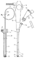
図2は、内視鏡10の可撓性挿入部11,12,13に外套シース20が被せられ、案内チューブ17の基端側接続筒17bに吸引アダプタ30が取り付けられた使用状態を示しており、外套シース20の基端に配置されている外套シース固定ネジ25が締め付けられて、連結環24が可撓管11と操作部15との連結部付近に固定されている。
【0022】
その結果、外套シース20によって内視鏡10の可撓性挿入部11,12,13が外部環境から絶縁され、被覆チューブ21が軸線方向に弾力的に引き伸ばされて、先端キャップ22が先端部本体13の先端面に密着した状態になっている。
【0023】
そして、吸引チューブ40が吸引アダプタ30に接続され、吸引アダプタ30に通して引き出されたチャンネルチューブ23の基端部が、操作部15に配置された接続装置50において送気送水分離チューブ51に接続されている。
【0024】
吸引アダプタ30には、チャンネルチューブ23を吸引アダプタ30に固定するための手動のチャンネル固定ネジ38が配置されており、案内チューブ17に通された状態のチャンネルチューブ23の基端寄りの部分を、チャンネル固定ネジ38で吸引アダプタ30に任意に固定することができる。
【0025】
そして、チャンネルチューブ23は、図2に矢印A、Bで示されるように、先端キャップ22とチャンネル固定ネジ38との間で軸線周りに捩じった状態にセットされて、チャンネル固定ネジ38により吸引アダプタ30に固定されている。
【0026】
チャンネルチューブ23の捩じり角度は、例えば90°〜180°程度である。その結果、チャンネルチューブ23が自己の弾性で元の状態に戻ろうとする回転力(矢印A、Bと逆方向の回転力)が先端キャップ22とチャンネル固定ネジ38とに作用している。
【0027】
図5は、吸引アダプタ30の内部の状態を示しており、吸引アダプタ30には、基端側接続筒17bに差し込み接続される接続筒31内から真っ直ぐに貫通するチャンネルチューブ通過孔32が形成されている。39は、操作部15に固定的に突設されている基端側接続筒17bに手動で螺合する固定ナットである。
【0028】
チャンネルチューブ通過孔32の中間部分から斜め方向に分岐する方向に処置具差込孔33が形成されていて、さらにその処置具差込孔33の途中から分岐して外方に突出する吸引口金36に吸引チューブ40が接続されている。処置具差込孔33の突端部は処置具挿入口34になっていて、そこにシール機能を有するゴム製の鉗子栓35が取り付けられている。
【0029】
そして、チャンネルチューブ通過孔32内を通過するチャンネルチューブ23に形成されている側孔23aは、チャンネルチューブ通過孔32部分における処置具差込孔33の開口を臨む状態に位置し、処置具差込孔33の開口より前後両方向にはみ出すように大きく形成されている。
【0030】
また、そのような側孔23aの前後位置においてチャンネルチューブ通過孔32とチャンネルチューブ23との間の隙間をシールするためのゴム製の一対のOリング37が配置されていて、吸引アダプタ30の内部が吸引チューブ40内とチャンネルチューブ23の処置具通過路兼吸引路23S以外の部分と通気しないようになっている。
【0031】
チャンネル固定ネジ38は、チャンネルチューブ通過孔32の外端側口元に形成されている雌ネジ部に対して螺合しており、チャンネルチューブ23をチャンネルチューブ通過孔32に通してチャンネル固定ネジ38を締め込むことにより、その内側に配置されているOリング37が押し潰されてチャンネルチューブ23を外側から締め付ける。
【0032】
その結果、チャンネルチューブ23が吸引アダプタ30に固定された状態になり、チャンネルチューブ23を緩めれば吸引アダプタ30とチャンネルチューブ23との固定状態が解除される。
【0033】
そのような構成により、吸引チューブ40から吸引をすれば、その吸引力が処置具差込孔33から側孔23aを介してチャンネルチューブ23の処置具通過路兼吸引路23Sに作用し、処置具通過路兼吸引路23Sを通じて体内汚液等を吸引することができる。
【0034】
また、処置具挿入口34から処置具100を差し込めば、その処置具100が処置具差込孔33からチャンネルチューブ23の側孔23aを経由して処置具通過路兼吸引路23S内に挿入され、体内組織の採取その他の内視鏡的処置を行うことができる。
【0035】
図6は、内視鏡10の可撓性挿入部11,12,13に外套シース20が被覆された状態の先端部分を示し、図1は、先端部本体13から先端キャップ22が外された状態を、被覆チューブ21を省略して示している。
【0036】
図6に示されるように、可撓性挿入部11,12,13に外套シース20が被覆された状態では、先端キャップ22の先端内面が先端部本体13の先端外面に密着し、外套シース20のチャンネルチューブ23が内視鏡10の案内チューブ17内に通されている。
【0037】
そして、先端部本体13内においてチャンネルチューブ23が通過する部分には、VII−VII断面を図示する図7に示されるように、チャンネル変形空間19が形成されていて、チャンネルチューブ23がチャンネル変形空間19内で弾性変形することができる。
【0038】
また、図1に示されるように、先端キャップ22と先端部本体13には、先端キャップ22内から先端部本体13が後方に抜け出すのを規制するための爪状部28と溝状部18からなる抜け止め機構が設けられている。
【0039】
この実施例においては、爪状部28は、先端キャップ22の内周面の4ヵ所にL字状に突出形成され、溝状部18は、爪状部28が係脱できるように先端部本体13の外周面の4ヵ所にL字状に窪んで形成されている。
【0040】
図8は、その爪状部28と溝状部18の係合状態を示しており、爪状部28の爪部分28aが溝状部18の段差部分18aに係合することにより、先端キャップ22と先端部本体13とが軸線方向に相対的に移動できない抜け止め状態になる。
【0041】
そして、チャンネルチューブ23が軸線周りに捩じってセットされていることにより、その捩じり方向と逆方向(図8に示される「反A方向」)の回転力が先端キャップ22を軸線周りに回転させ、先端キャップ22の爪部分28aが先端部本体13の段差部分18aに係合する抜け止め状態になって、その状態を維持している。
【0042】
そのような抜け止め状態を解除するには、溝状部18が爪状部28より周方向に幅広に形成されているので、先端キャップ22を先端部本体13の周りにA方向に回転させればよく、チャンネル固定ネジ38を緩めてからそれを行えばより簡単に回転させることができる。
【0043】
そのように先端キャップ22を回転させることにより、チャンネルチューブ23がチャンネル変形空間19内で変形しながら、図9に示されるように爪部分28aが段差部分18aから外れて、先端部本体13を先端キャップ22内から後方に抜き出すことができる抜け止め解除状態になる。
【0044】
なお、外套シース20を可撓性挿入部11,12,13に被覆する際には、爪状部28の先端の角部分が斜面状に形成されているので、爪状部28が溝状部18内にスムーズに導入される。
【0045】
なお、本発明は上記実施例に限定されるものではなく、例えば案内チューブ17が可撓性挿入部11,12,13内に挿通配置されずに、可撓性挿入部11,12,13の外表面から凹んだ溝状に形成されている装置等であっても、上述の実施例と同様に本発明を適用することができる。
【0046】
【発明の効果】
本発明によれば、軸線周りに捩じってセットされたチャンネルチューブが自己の弾性により元の状態に戻ろうとする回転力により、可撓性挿入部の先端部分が外套シースの先端部分内から抜け出すのを規制する抜け止め機構が係合状態になり、チャンネルチューブの先端が固着されている外套シースの先端部分を逆方向に回転させるだけで抜け止め機構の係合を解除することができるので、部材を破損する恐れなく抜け止め機構を確実に係脱させることができる。
【図面の簡単な説明】
【図1】本発明の実施例の外套シース付内視鏡の可撓性挿入部から外套シースが外された状態を一部を省略して示す斜視図である。
【図2】本発明の実施例の外套シース付内視鏡の側面図である。
【図3】本発明の実施例の外套シース付内視鏡の使用準備状態の側面一部断面図である。
【図4】本発明の実施例の図3におけるIV−IV断面図である。
【図5】本発明の実施例の外套シース付内視鏡の吸引アダプタ部分の側面断面図である。
【図6】本発明の実施例の外套シース付内視鏡の可撓性挿入部に外套シースが被覆された状態の先端部分の側面断面図である。
【図7】本発明の実施例の図6におけるVII−VII断面図である。
【図8】本発明の実施例の抜け止め機構の係合状態の側面断面図である。
【図9】本発明の実施例の抜け止め機構の係合解除状態の側面断面図である。
【符号の説明】
10 内視鏡
11 可撓管(可撓性挿入部)
12 湾曲部(可撓性挿入部)
13 先端部本体(可撓性挿入部の先端部分)
17 案内チューブ(案内管路)
18 溝状部(抜け止め機構)
18a 段差部分
19 チャンネル変形空間
20 外套シース
21 被覆チューブ
22 先端キャップ
23 チャンネルチューブ
28 爪状部(抜け止め機構)
28a 爪部分
30 吸引アダプタ
32 チャンネルチューブ通過孔
38 チャンネル固定ネジ[0001]
BACKGROUND OF THE INVENTION
The present invention relates to an endoscope with a sheath sheath having a sheath sheath for preventing the flexible insertion portion of the endoscope from being contaminated.
[0002]
[Prior art]
In order to prevent infection between patients through an endoscope in an endoscopic examination, a flexible sheath of the endoscope is covered with a mantle sheath, and the mantle sheath is subjected to endoscopic examination. It should be replaced every time.
[0003]
In order to make it possible to use the treatment instrument during the endoscopic examination, a channel tube for passing the treatment instrument is provided on the outer sheath, and a guide conduit provided on the flexible insertion portion side. The channel tube is configured to pass through.
[0004]
In such an endoscope with a sheath, during the endoscopy, the distal end portion of the sheath sheath that is covered with the distal end portion of the flexible insertion portion where the observation window or the like is disposed is provided. It is necessary not to move.
[0005]
Therefore, conventionally, a retaining mechanism including a claw mechanism for restricting the distal end portion of the flexible insertion portion from being pulled backward from the distal end of the outer sheath is provided, and the flexible sheath is flexed from the outer sheath after the endoscopic examination is completed. When extracting the sexual insertion portion, the distal end member of the outer sheath formed in a cap shape is crushed from the outside and elastically deformed in the radial direction so as to disengage the claw mechanism (for example, Patent Document 1). Patent Document 2).
[0006]
[Patent Document 1]
Japanese Patent Laid-Open No. 3-1903023 [Patent Document 2]
Japanese Utility Model Publication No. 7-33301 [0007]
[Problems to be solved by the invention]
However, when the claw mechanism is disengaged, if the distal end member of the outer sheath formed in a cap shape is crushed from the outside and elastically deformed, the force may not be controlled and the engagement may not be disengaged. In other cases, the tip of the outer sheath may be damaged due to excessive force.
[0008]
Therefore, the present invention provides a sheath sheath with a sheath sheath that can securely and securely disengage a retaining mechanism for restricting the distal end portion of the flexible insertion portion from slipping out of the distal end portion of the sheath sheath. An object is to provide an endoscope.
[0009]
[Means for Solving the Problems]
In order to achieve the above object, an endoscope with a sheath sheath according to the present invention is configured such that a channel tube is inserted into a sheath sheath that is detachably covered by a flexible insertion portion of the endoscope so that the distal end of the channel tube is inserted. Is fixed to the distal end of the outer sheath, and a guide channel through which the channel tube is passed in the state where the outer sheath is covered by the flexible insertion portion is provided in the flexible insertion portion, and the distal end of the flexible insertion portion In an endoscope with a sheath sheath provided with a detachable retaining mechanism for restricting the portion from slipping out of the distal end portion of the sheath sheath, the sheath sheath is covered with a flexible insertion portion, and the channel tube is With the channel tube inserted through the guide pipe, set the channel tube to be twisted around the axis between both ends of the guide pipe, and the channel tube will return to its original shape with its own elasticity. Retaining mechanism by the rotating force of returning to become engaged, in which therewith to be able to release the engagement of the retaining mechanism by applying a rotational force in the opposite direction.
[0010]
The retaining mechanism is formed on the outer surface of the distal end portion of the flexible insertion portion and on the inner surface of the distal end portion of the outer sheath so as to be detachable from the groove portion. You may have a nail | claw-shaped part.
[0011]
DETAILED DESCRIPTION OF THE INVENTION
Embodiments of the present invention will be described with reference to the drawings.
In FIG. 3, 10 is an endoscope, 20 is an outer sheath that is detachably covered by the
[0012]
The
[0013]
A
[0014]
Inside the
[0015]
On the
[0016]
The connecting
[0017]
A
[0018]
The
[0019]
An
[0020]
4 is a cross-sectional view of the
[0021]
FIG. 2 shows a usage state in which the
[0022]
As a result, the
[0023]
Then, the
[0024]
The
[0025]
Then, as indicated by arrows A and B in FIG. 2, the
[0026]
The twist angle of the
[0027]
FIG. 5 shows an internal state of the
[0028]
A treatment
[0029]
The
[0030]
In addition, a pair of rubber O-
[0031]
The
[0032]
As a result, the
[0033]
With such a configuration, when suction is performed from the
[0034]
When the
[0035]
FIG. 6 shows the distal end portion of the
[0036]
As shown in FIG. 6, in a state where the
[0037]
And in the part which the
[0038]
Further, as shown in FIG. 1, the
[0039]
In this embodiment, the claw-shaped
[0040]
FIG. 8 shows an engagement state between the claw-shaped
[0041]
Since the
[0042]
In order to release such a retaining state, the groove-
[0043]
By rotating the
[0044]
When the
[0045]
In addition, this invention is not limited to the said Example, For example, the
[0046]
【The invention's effect】
According to the present invention, the distal end portion of the flexible insertion portion is moved from the distal end portion of the outer sheath by the rotational force that the channel tube set by twisting around the axis returns to its original state by its own elasticity. Since the retaining mechanism that restricts the slipping out is engaged, the retaining mechanism can be released simply by rotating the distal end portion of the outer sheath to which the distal end of the channel tube is fixed in the reverse direction. The retaining mechanism can be securely engaged and disengaged without fear of damaging the member.
[Brief description of the drawings]
FIG. 1 is a perspective view showing a state in which a mantle sheath has been removed from a flexible insertion portion of an endoscope with mantle sheath according to an embodiment of the present invention.
FIG. 2 is a side view of the endoscope with a sheath sheath according to the embodiment of the present invention.
FIG. 3 is a partial cross-sectional side view of the endoscope with a sheath sheath according to the embodiment of the present invention in a ready state for use.
4 is a cross-sectional view taken along the line IV-IV in FIG. 3 according to the embodiment of the present invention.
FIG. 5 is a side sectional view of the suction adapter portion of the endoscope with a sheath sheath according to the embodiment of the present invention.
FIG. 6 is a side cross-sectional view of the distal end portion of the endoscope with a sheath sheath according to the embodiment of the present invention in a state where the sheath is covered on the flexible insertion portion.
7 is a cross-sectional view taken along the line VII-VII in FIG. 6 according to the embodiment of the present invention.
FIG. 8 is a side sectional view of the engagement state of the retaining mechanism according to the embodiment of the present invention.
FIG. 9 is a side sectional view showing a disengagement state of the retaining mechanism according to the embodiment of the present invention.
[Explanation of symbols]
10
12 Curved part (flexible insertion part)
13 Tip body (tip part of flexible insert)
17 Guide tube (guide line)
18 Groove (Retaining mechanism)
18a Stepped
Claims (2)
上記外套シースが上記可撓性挿入部に被覆されて上記チャンネルチューブが上記案内管路に挿通された状態において、上記チャンネルチューブを上記案内管路の両端の間において軸線周りに捩じった状態にセットして、上記チャンネルチューブが自己の弾性で元の状態に戻ろうとする回転力によって上記抜け止め機構が係合状態になり、それと逆方向の回転力を加えることにより上記抜け止め機構の係合状態を解除することができるようにしたことを特徴とする外套シース付内視鏡。A channel tube is inserted and disposed in an outer sheath that is detachably covered by the flexible insertion portion of the endoscope, and the distal end of the channel tube is fixed to the distal end of the outer sheath, and the outer sheath is the flexible sheath. A guide conduit through which the channel tube is passed in the state covered with the insertion portion is provided in the flexible insertion portion, and the distal end portion of the flexible insertion portion is pulled out from the distal end portion of the outer sheath. In an endoscope with an outer sheath provided with a detachable retaining mechanism for restricting
In a state where the outer sheath is covered with the flexible insertion portion and the channel tube is inserted through the guide conduit, the channel tube is twisted around the axis between both ends of the guide conduit. The channel tube is engaged by the rotational force of the channel tube to return to its original state by its own elasticity, and by applying a rotational force in the opposite direction to the channel tube, the channel tube is engaged. An endoscope with an outer sheath, wherein the combined state can be released.
Priority Applications (1)
| Application Number | Priority Date | Filing Date | Title |
|---|---|---|---|
| JP2003047247A JP4199560B2 (en) | 2003-02-25 | 2003-02-25 | Endoscope with sheath |
Applications Claiming Priority (1)
| Application Number | Priority Date | Filing Date | Title |
|---|---|---|---|
| JP2003047247A JP4199560B2 (en) | 2003-02-25 | 2003-02-25 | Endoscope with sheath |
Publications (2)
| Publication Number | Publication Date |
|---|---|
| JP2004254823A JP2004254823A (en) | 2004-09-16 |
| JP4199560B2 true JP4199560B2 (en) | 2008-12-17 |
Family
ID=33113545
Family Applications (1)
| Application Number | Title | Priority Date | Filing Date |
|---|---|---|---|
| JP2003047247A Expired - Fee Related JP4199560B2 (en) | 2003-02-25 | 2003-02-25 | Endoscope with sheath |
Country Status (1)
| Country | Link |
|---|---|
| JP (1) | JP4199560B2 (en) |
Families Citing this family (7)
| Publication number | Priority date | Publication date | Assignee | Title |
|---|---|---|---|---|
| JP2009089725A (en) * | 2007-10-03 | 2009-04-30 | Olympus Corp | Separate type endoscope |
| JP2009089724A (en) * | 2007-10-03 | 2009-04-30 | Olympus Corp | Separate type endoscope |
| JP5289812B2 (en) * | 2008-03-31 | 2013-09-11 | オリンパスメディカルシステムズ株式会社 | Endoscope, endoscope with tip cap, and cleaning sheath for endoscope |
| JP2012187138A (en) * | 2011-03-08 | 2012-10-04 | Fujifilm Corp | Rigid endoscope |
| JP6052557B2 (en) * | 2011-11-01 | 2016-12-27 | 武漢佑康科技有限公司 | Integrated soft endoscope that can be adjusted in all directions |
| JP6713879B2 (en) * | 2016-08-29 | 2020-06-24 | 富士フイルム株式会社 | Endoscope |
| CN116236229A (en) * | 2023-02-22 | 2023-06-09 | 深圳微创踪影医疗装备有限公司 | Ultrasound imaging system and ultrasound imaging catheter assembly |
-
2003
- 2003-02-25 JP JP2003047247A patent/JP4199560B2/en not_active Expired - Fee Related
Also Published As
| Publication number | Publication date |
|---|---|
| JP2004254823A (en) | 2004-09-16 |
Similar Documents
| Publication | Publication Date | Title |
|---|---|---|
| JP4131012B2 (en) | Endoscope with sheath | |
| US5458132A (en) | Endoscope cover-sheathed endoscope system | |
| CN101637408B (en) | Endoscope insertion aid and endoscope apparatus | |
| US6908428B2 (en) | Sleeve for endoscopic tools | |
| JP5273980B2 (en) | Endoscope ligation tool and endoscope ligation system | |
| US7762949B2 (en) | Endoscope with open channels | |
| JP3831683B2 (en) | Bending prevention of flexible tube insertion part of endoscope with outer sheath | |
| KR20080078821A (en) | Protective sleeve for endoscope tools | |
| JP4199560B2 (en) | Endoscope with sheath | |
| JPH07184830A (en) | Endoscope cover type endoscope apparatus | |
| JP5686711B2 (en) | Endoscope plug body and endoscope having the same | |
| JP4261215B2 (en) | Endoscope with sheath | |
| JP3376852B2 (en) | Endoscope device | |
| JP2005230084A (en) | Balloon attaching tool | |
| JP4349830B2 (en) | Endoscope with sheath | |
| JP3859489B2 (en) | Endoscope with sheath | |
| JP4542351B2 (en) | Endoscope | |
| JP3911151B2 (en) | Endoscope contamination prevention device | |
| JP4242175B2 (en) | Endoscope with sheath | |
| JP4047026B2 (en) | Endoscope contamination prevention device | |
| JP3934408B2 (en) | Endoscope contamination prevention device | |
| JP3949968B2 (en) | Endoscope with sheath | |
| JP3914441B2 (en) | Endoscope with sheath | |
| JP3989773B2 (en) | Endoscope with sheath | |
| JP3869700B2 (en) | Endoscope with sheath |
Legal Events
| Date | Code | Title | Description |
|---|---|---|---|
| A621 | Written request for application examination |
Free format text: JAPANESE INTERMEDIATE CODE: A621 Effective date: 20051110 |
|
| A711 | Notification of change in applicant |
Free format text: JAPANESE INTERMEDIATE CODE: A712 Effective date: 20080501 |
|
| A977 | Report on retrieval |
Free format text: JAPANESE INTERMEDIATE CODE: A971007 Effective date: 20080917 |
|
| TRDD | Decision of grant or rejection written | ||
| A01 | Written decision to grant a patent or to grant a registration (utility model) |
Free format text: JAPANESE INTERMEDIATE CODE: A01 Effective date: 20080925 |
|
| A01 | Written decision to grant a patent or to grant a registration (utility model) |
Free format text: JAPANESE INTERMEDIATE CODE: A01 |
|
| A61 | First payment of annual fees (during grant procedure) |
Free format text: JAPANESE INTERMEDIATE CODE: A61 Effective date: 20081003 |
|
| FPAY | Renewal fee payment (event date is renewal date of database) |
Free format text: PAYMENT UNTIL: 20111010 Year of fee payment: 3 |
|
| R150 | Certificate of patent or registration of utility model |
Free format text: JAPANESE INTERMEDIATE CODE: R150 |
|
| LAPS | Cancellation because of no payment of annual fees |