JP4199909B2 - Screw fastener - Google Patents
Screw fastener Download PDFInfo
- Publication number
- JP4199909B2 JP4199909B2 JP2000180078A JP2000180078A JP4199909B2 JP 4199909 B2 JP4199909 B2 JP 4199909B2 JP 2000180078 A JP2000180078 A JP 2000180078A JP 2000180078 A JP2000180078 A JP 2000180078A JP 4199909 B2 JP4199909 B2 JP 4199909B2
- Authority
- JP
- Japan
- Prior art keywords
- screw
- plug
- rods
- fixing tool
- cross
- Prior art date
- Legal status (The legal status is an assumption and is not a legal conclusion. Google has not performed a legal analysis and makes no representation as to the accuracy of the status listed.)
- Expired - Fee Related
Links
Images




Classifications
-
- F—MECHANICAL ENGINEERING; LIGHTING; HEATING; WEAPONS; BLASTING
- F16—ENGINEERING ELEMENTS AND UNITS; GENERAL MEASURES FOR PRODUCING AND MAINTAINING EFFECTIVE FUNCTIONING OF MACHINES OR INSTALLATIONS; THERMAL INSULATION IN GENERAL
- F16B—DEVICES FOR FASTENING OR SECURING CONSTRUCTIONAL ELEMENTS OR MACHINE PARTS TOGETHER, e.g. NAILS, BOLTS, CIRCLIPS, CLAMPS, CLIPS OR WEDGES; JOINTS OR JOINTING
- F16B13/00—Dowels or other devices fastened in walls or the like by inserting them in holes made therein for that purpose
- F16B13/12—Separate metal or non-separate or non-metal dowel sleeves fastened by inserting the screw, nail or the like
- F16B13/124—Separate metal or non-separate or non-metal dowel sleeves fastened by inserting the screw, nail or the like fastened by inserting a threaded element, e.g. screw or bolt
Landscapes
- Engineering & Computer Science (AREA)
- General Engineering & Computer Science (AREA)
- Mechanical Engineering (AREA)
- Dowels (AREA)
- Joining Of Building Structures In Genera (AREA)
Description
【0001】
【発明の属する技術分野】
この発明は、コンクリートやモルタル等の建築物にねじを用いて器具や器材を取り付けるために使用するねじ固着具とこの固着具とねじの組合せ体に関する。
【0002】
【従来の技術】
従来、コンクリートやモルタル等の建築物にねじを用いて器具や器材を取り付ける方法は、コンクリートやモルタルに下孔を穿設した後、この下孔内に円筒状のプラグを挿入し、コンクリートやモルタルに重ねた器具や器材にねじを挿通し、このねじを下孔内のプラグにねじ込むことにより、ねじがプラグを拡張し、コンクリートやモルタルに対して器具や器材を締結するようにしている。
【0003】
【発明が解決しようとする課題】
ところで、上記のような従来のプラグは、ねじのねじ込みで均等に拡張して下孔の内周面に圧着し、ねじと下孔の間の空間の発生をなくすことにより締結力を得ようとするものであるが、拡張したプラグの外面と、コンクリート又はモルタルの内壁面の摩擦によって、プラグとコンクリート又はモルタルとの滑りを防ぐ構造であるために、材質的に脆くて壊れやすい性質のコンクリートやモルタルに対して空転が発生しやすいという問題がある。
【0004】
そこで、この発明の課題は、下孔に挿入したプラグに対してねじをねじ込むことにより、プラグが不均一に変形移動し、ねじ山が下孔とプラグの両者にそれぞれ直接食い込み、材質的に脆くて壊れやすい性質のコンクリートやモルタルに対してねじ山の食い込み量を十分に確保でき、しかも、プラグによる締結力の強化が図れるねじ固着具と、この固着具とねじの組合せ体を提供することにある。
【0005】
【課題を解決するための手段】
上記のような課題を解決するため、この発明は、ねじをねじ込むために設けた下孔内に挿入するプラグが、二本の柔軟な材質でできた棒体を平行になるように部分的に接続し、両棒体の一端側に、棒体の断面形状よりも大きな頭部をそれぞれ設け、両頭部の互いに対向する面側の位置に、組み合わせ使用するねじの先端部のガイド孔を二本の棒体間の中心と同軸上の配置で設けて形成され、このプラグが挿入された前記下孔に対してガイド孔から棒体間にねじ込んだねじのねじ山が下孔と棒体の両者にそれぞれ直接食い込むよう、このプラグの断面最大幅を組み合わせ使用するねじのねじ山径よりも小さく設定した構成を採用したものである。
【0007】
ここで、上記プラグのガイド孔にねじの先端部を嵌合することにより、ねじ固着具とねじを接続状態にセットした組み合わせ体とすることができる。
【0008】
【発明の実施の形態】
以下、この発明の実施の形態を図示例と共に説明する。
【0009】
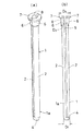
図1と図2は、この発明のねじ固着具1の基本構造を示し、ねじ固着具1は、合成樹脂等の柔軟性のある材質を用いた二本の棒体2、2が平行になるように部分的に接続されたプラグ1aに形成され、このプラグ1aの断面最大幅D1 を組み合わせ使用するタッピングねじや木ねじの如きねじ3のねじ山径D2 よりも小さく設定したものである。
【0010】
図1(a)に示す例のプラグ1aは、二本の棒体2、2を断面円軸状とし、両棒体2、2を先端接続部4で二本の棒体2、2が平行になるように結合して形成されている。
【0011】
図1(b)に示す例のプラグ1aは、二本の棒体2、2を断面円軸状とし、両棒体2、2の中間複数箇所を細い線状の接続部5で互いに結合し、二本の棒体1、1が平行になるようにしたものである。なお、何れの例においても、二本の棒体2、2の軸方向の長さは、組み合わせ使用するねじ3の長さに合わせて設定すればよい。
【0012】
図3に示すこの発明のねじ固着具1は、プラスチック等の柔軟性のある材質を用いた二本の棒体2、2を、先端接続部4と中間部の細い線状の接続部5で互いに結合し、二本の棒体2、2が平行になるようにすると共に、両棒体2、2の上端側に、棒体2、2の断面形状よりも大きな軸状部6と、この軸状部6の端部に該軸状部6の断面形状よりも大きな頭部7をそれぞれ設けてプラグ1aを形成し、上記両棒体2、2に設けた頭部7から軸状部6の互いに対向する面側の位置に、組み合わせ使用するねじ3の先端部のガイド孔8を設けた構造になっている。
【0013】
上記二本の棒体2、2は、図4(b)に示す場合、外径の弧状面と内側の傾斜面を備えた断面形状になっており、この棒体2、2の上端に連ねて設けた軸状部6とその上端の頭部7は断面半円形になり、両棒体2、2の頭部7から軸状部6の互いに対向する面側の位置に設けたガイド孔8は、二本の棒体2、2間の中心と同軸上に配置され、組み合わせ使用するねじ3の先端部をこのガイド孔8に嵌合もしくは螺合することにより、図4(a)の如く、プラグ1aとねじ3を同軸状の接続状態にセットした組み合わせ体を形成することができる。
【0014】
この発明のねじ固着具1において、軸状部6の外径D3 はねじ3のねじ山径D2 と等しいかそれよりも小径に設定され、頭部7の外径D4 は軸状部6の外径D3 及び下孔よりも大径となり、プラグ1aの断面最大幅D1 はねじ3のねじ山径D2 よりも小さく設定されている。
【0015】
図5(a)乃至(i)の各々は、この発明のねじ固着具1において、二本の棒体2、2に採用する断面形状の異なった例を示し、円形、角形、多角形、半円形、三角形等任意の断面形状を採用でき、(a)乃至(e)は棒体2、2に等しい断面形状を組み合わせ例を示し、また、(f)乃至(i)は棒体2、2に異なる断面形状や同形の大小を組み合わせ例を示している。
【0016】
この発明のねじ固着具は、上記のような構成であり、次にこのねじ固着具1を用いた締結方法を説明する。
【0017】
図6(a)のように、コンクリートやモルタル等の建築物Aやブロック等の表面に機器や器材等の被固定物Bを重ね、この被固定物Bから建築物Aに、建築物Aやブロック等の性状に応じてねじのねじ山径と略同じかそれよりも少し大きめもしくは小さめの内径と、ねじの長さに対応する深さの下孔Cをドリル11で穿設し、次に、図6(b)のように、この下孔Cにねじ固着具1の棒体2、2を挿入する。
【0018】
この状態で、ねじ固着具1のガイド孔8から二本の棒体2、2間に向けてねじ3をねじ込む。ねじ込んだねじ3が、頭部7から軸部6間を通過して棒体2、2間に進入すると、棒体2、2は断面最大幅D1 がねじ3のねじ山径よりも小さく設定されているので、棒体2、2間へのねじ3の進入を許容し、棒体2、2はねじ3の回転方向の一方に押しやられ、この結果、図7(b)のように、下孔Cに対してねじ3は偏心した配置になり、これにより、ねじ3のねじ山3aはコンクリートやモルタル面と棒体2、2の双方にわたってねじ山を切りつつ進入し、ねじ3の頭部3bで被固定物Bを締めつけて締結が完了する。
【0020】
上記ねじ3による締結時において、ねじ固着具1を柔軟性のある合成樹脂で形成することにより、棒体2、2間へのねじ3のねじ込み回転時に高熱が発生し、この熱で棒体2、2が解けてねじ3に接着し、ねじ3の緩み止め効果が増大すると共に、合成樹脂製のねじ固着具1は微振動を吸収することができる。
【0021】
また、合成樹脂製の棒体2、2が保護パッキンの役目を果たし、ねじ込み締結後のオーバートルクを吸収し、棒体2、2に形成されたねじ山が壊れるのを防止することができると共に、圧縮を受けて変形した棒体2、2は、コンクリートやモルタル面に圧着するので、ねじ3の数回の取り外しが可能で、締結強度の低下もない。
【0022】
なお、この発明のねじ固着具1においては、棒体2、2の上端に軸状部6と頭部7を設けたものにおいては、ねじ3のねじ込み開始直後に軸状部6が押し開かれ、下孔Cとの摩擦によって、ねじ固着具1の空転を防止することができる。
【0023】
さらに、棒体2、2を可破壊性の接続部で接続してあるので、棒体2、2間へのねじの進入時に、接続部5が下孔Cの軸心に対してねじ3を一方に偏心させる誘導部となると共に、この接続部5はねじ3のねじ込みによる圧力で切れることにより、役目を終わる。
【0024】
このように、建築物Aの表面に機器や器材等の被固定物Bを固定する際に、被固定物Bと建築物Aに対して重ね合わせ状態で同時に下孔Cを穿設し、この下孔Cにねじ固着具1を挿入することで、建築物Aと被固定物Bに下孔を別々に設ける場合のような下孔合わせのような作業が不要になり、被固定物が長尺物の場合に特に有利であり、作業能率の大幅な向上が図れる。
【0025】
【発明の効果】
以上のように、この発明によると、二本の柔軟な材質でできた棒体が平行になるように部分的に接続されたプラグに形成され、このプラグの断面最大幅を組み合わせ使用するねじのねじ山径よりも小さく設定したので、ねじの進入に対して棒体はねじの回転方向の一方に押しやられ、この結果、下孔の軸心に対してねじは偏心した配置になり、これにより、ねじのねじ山はコンクリートやモルタル面と棒体の双方にわたってねじ山を切りつつ進入し、緩みのない強固な締結が得られると共に、棒体が保護パッキンの役目を果たし、ねじ込み締結後のオーバートルクを吸収し、棒体に形成されたねじ山が壊れるのを防止することができると共に、圧縮を受けて変形した棒体は、コンクリートやモルタル面に圧着するので、ねじの数回の取り外しが可能で、締結強度の低下もない。
【0026】
また、棒体の一方端部に軸部と頭部を設けたねじ固着具は、ねじのねじ込み開始直後に軸部が開いて拡開し、下孔との摩擦によって、ねじ固着具の空転を防止することができる。
【0027】
さらに、ねじ固着具とねじの組合せ体は、そのままの状態でねじ固着具を下孔に挿入して使用することができ、ねじのねじ込みによる締結作業が能率よく行える。
【図面の簡単な説明】
【図1】(a)はこの発明に係るねじ固着具における基本構造を示す第1の例の正面図、(b)は同第2の例を示す正面図
【図2】(a)はねじの正面図、(b)はねじ固着具とねじの直径の関係を示す横断面図
【図3】(a)はこの発明のねじ固着具を示す斜視図、(b)は同正面図
【図4】(a)はねじ固着具とねじの組み合わせ体を示す正面図、(b)はその棒体の拡大横断面図
【図5】(a)乃至(i)の各々はねじ固着具における棒体の断面形状の異なる例を示す横断面図
【図6】(a)と(b)はねじ固着具を用いて行う被固定物の締結の工程を順番に示す説明図
【図7】(a)はねじ固着具による被固定物の締結状態を示す拡大縦断面図、(b)は同横断平面図
【符号の説明】
1 ねじ固着具
1a プラグ
2 棒体
3 ねじ
4 先端接続部
5 接続部
6 軸状部
7 頭部
8 ガイド孔[0001]
BACKGROUND OF THE INVENTION
The present invention relates to a screw fixing tool used for attaching an instrument or equipment to a building such as concrete or mortar by using a screw and a combination of the fixing tool and the screw.
[0002]
[Prior art]
Conventionally, a method of attaching an instrument or equipment to a building such as concrete or mortar by using a screw is to drill a pilot hole in the concrete or mortar, and then insert a cylindrical plug into the concrete hole or mortar. A screw is inserted into a tool or equipment stacked on top of each other, and this screw is screwed into a plug in the pilot hole so that the screw expands the plug and fastens the equipment or equipment to concrete or mortar.
[0003]
[Problems to be solved by the invention]
By the way, the conventional plug as described above tries to obtain a fastening force by uniformly expanding the screw by screwing it in and crimping it to the inner peripheral surface of the pilot hole, thereby eliminating the space between the screw and the pilot hole. However, because the structure prevents the sliding of the plug and the concrete or mortar by friction between the outer surface of the expanded plug and the inner wall of the concrete or mortar, There is a problem that slipping easily occurs with respect to mortar.
[0004]
Accordingly, an object of the present invention is to screw the screw into the plug inserted into the lower hole, so that the plug is deformed and moved unevenly, and the screw thread directly bites into both the lower hole and the plug, making the material brittle. To provide a screw fixing tool that can secure a sufficient amount of screw thread penetration against concrete and mortar that is fragile and that can enhance the fastening force by a plug, and a combination of this fixing tool and screw. is there.
[0005]
[Means for Solving the Problems]
In order to solve the problems as described above, the present invention is partially adapted so that a plug inserted into a pilot hole provided for screwing a screw is parallel to a rod body made of two flexible materials. Connect the two heads to one end of each rod, and provide two heads larger than the cross-sectional shape of the rods. The thread of the screw screwed between the rod body from the guide hole to the lower hole into which the plug is inserted is formed on both the lower hole and the rod body. A configuration is adopted in which the maximum cross-sectional width of the plug is set to be smaller than the thread diameter of the screw to be used so as to directly bite into each.
[0007]
Here, by fitting the tip of the screw into the guide hole of the plug, a combined body in which the screw fixing tool and the screw are set in a connected state can be obtained.
[0008]
DETAILED DESCRIPTION OF THE INVENTION
Hereinafter, embodiments of the present invention will be described with reference to the drawings.
[0009]
1 and 2 show a basic structure of a
[0010]
The
[0011]
The
[0012]
A
[0013]
In the case shown in FIG. 4 (b), the two
[0014]
In the
[0015]
5 (a) to 5 (i) show examples of different cross-sectional shapes adopted for the two
[0016]
Threaded fastener of the present invention has a configuration as described above, will now be described fastening method had use of the
[0017]
As shown in FIG. 6 (a), a fixed object B such as equipment or equipment is stacked on the surface of a building A such as concrete or mortar or a block, and the building A or the building A or the like. Depending on the properties of the block or the like, a
[0018]
In this state, the
[0020]
When the
[0021]
In addition, the
[0022]
In the
[0023]
Further, since the
[0024]
Thus, when fixing the fixed object B such as equipment and equipment to the surface of the building A, the prepared hole B and the building A are simultaneously drilled with the pilot hole C in an overlapped state. Inserting the
[0025]
【The invention's effect】
As described above, according to the present invention, the two rods made of a flexible material are formed in a plug that is partially connected so as to be parallel, and the screw that is used in combination with the maximum cross-sectional width of the plug is used. Since the thread diameter is set smaller than the thread diameter, the rod body is pushed to one side of the screw rotation direction as the screw enters, and as a result, the screw is arranged eccentrically with respect to the shaft center of the pilot hole. The thread of the screw enters the concrete and the mortar surface and the rod body while cutting the thread, and a firm fastening without loosening is obtained, and the rod body serves as a protective packing, and after the screwed fastening, It absorbs torque and prevents the thread formed on the rod from breaking, and the deformed rod is pressed against the concrete or mortar surface, so it can be removed several times. Possible, there is no reduction in the fastening strength.
[0026]
In addition, a screw fixing tool having a shaft and a head at one end of the rod body opens and expands immediately after the screw starts to be screwed, and the screw fixing tool is idled by friction with the lower hole. Can be prevented.
[0027]
Furthermore, the screw fastener and screw combination can be used by inserting the screw fastener into the pilot hole as it is, and the fastening operation by screwing the screw can be performed efficiently.
[Brief description of the drawings]
1A is a front view of a first example showing a basic structure of a screw fixing device according to the present invention, FIG. 1B is a front view of the second example, and FIG. 2A is a screw; FIG. 3B is a cross-sectional view showing the relationship between the screw fixing tool and the diameter of the screw. FIG. 3A is a perspective view showing the screw fixing tool of the present invention, and FIG. 4A is a front view showing a combination of a screw fixing tool and a screw, FIG. 5B is an enlarged cross-sectional view of the rod body, and FIGS. 5A to 5I are each a rod in the screw fixing tool. Cross-sectional views showing examples of different body cross-sectional shapes [FIG. 6] (a) and (b) are explanatory views sequentially showing the fastening process of an object to be fixed using a screw fixing tool. [FIG. ) Is an enlarged longitudinal sectional view showing a fastening state of an object to be fastened by a screw fixing tool, and (b) is a cross-sectional plan view thereof.
DESCRIPTION OF
Claims (1)
Priority Applications (2)
| Application Number | Priority Date | Filing Date | Title |
|---|---|---|---|
| JP2000180078A JP4199909B2 (en) | 2000-06-15 | 2000-06-15 | Screw fastener |
| DE2001103597 DE10103597A1 (en) | 2000-06-15 | 2001-01-26 | Screw anchor pin for concrete has two flexible rod sections in parallel partially bonded together to be distorted by the screw thread which bites into them and also the surrounding concrete in a firm anchor bond |
Applications Claiming Priority (1)
| Application Number | Priority Date | Filing Date | Title |
|---|---|---|---|
| JP2000180078A JP4199909B2 (en) | 2000-06-15 | 2000-06-15 | Screw fastener |
Publications (2)
| Publication Number | Publication Date |
|---|---|
| JP2001355618A JP2001355618A (en) | 2001-12-26 |
| JP4199909B2 true JP4199909B2 (en) | 2008-12-24 |
Family
ID=18681242
Family Applications (1)
| Application Number | Title | Priority Date | Filing Date |
|---|---|---|---|
| JP2000180078A Expired - Fee Related JP4199909B2 (en) | 2000-06-15 | 2000-06-15 | Screw fastener |
Country Status (2)
| Country | Link |
|---|---|
| JP (1) | JP4199909B2 (en) |
| DE (1) | DE10103597A1 (en) |
Families Citing this family (1)
| Publication number | Priority date | Publication date | Assignee | Title |
|---|---|---|---|---|
| MX2011013822A (en) | 2010-12-27 | 2012-06-26 | Shinetsu Chemical Co | Ceramic extrusion molding composition and binder. |
-
2000
- 2000-06-15 JP JP2000180078A patent/JP4199909B2/en not_active Expired - Fee Related
-
2001
- 2001-01-26 DE DE2001103597 patent/DE10103597A1/en not_active Withdrawn
Also Published As
| Publication number | Publication date |
|---|---|
| DE10103597A1 (en) | 2001-12-20 |
| JP2001355618A (en) | 2001-12-26 |
Similar Documents
| Publication | Publication Date | Title |
|---|---|---|
| US7682119B2 (en) | Screw for fastening wooden materials | |
| CN1247906C (en) | Pins and how to use them | |
| CN1289831C (en) | Plug to be fastened to hollow and solid building materials | |
| CA1141999A (en) | Expanding anchor bolt assembly | |
| CN1329603C (en) | Wall anchor for a screw, and assembly constituted by such a wall anchor and a screw | |
| US3056234A (en) | Wall and ceiling construction | |
| US20080124188A1 (en) | Concrete Screws | |
| WO2002068836A1 (en) | Dowel and method of using same | |
| US6712572B2 (en) | Expansion dowel | |
| US2470924A (en) | Fastening device | |
| US2931265A (en) | Drive socket insert for heads of screws and bolts | |
| TW200424446A (en) | Blind-setting coring rivet assembly | |
| KR100245528B1 (en) | Method for forming high strength fixed element inside solid wall layer | |
| KR101148327B1 (en) | Volume expansion type knife with length compression | |
| JP4060470B2 (en) | Screw fixing plug and combination of this plug and screw | |
| JPS6059385B2 (en) | Injection device for perforated joints | |
| JP4199909B2 (en) | Screw fastener | |
| EP0150906B1 (en) | Helical dowel | |
| JPS6129406B2 (en) | ||
| AU749876B2 (en) | Screw tipped anchor assembly | |
| JP4084891B2 (en) | Anchor device | |
| EP0441793B1 (en) | Wall tie | |
| KR102722004B1 (en) | the improved expandable type anchor structure | |
| CA2438691C (en) | Dowel and method of using same | |
| JPH0524725Y2 (en) |
Legal Events
| Date | Code | Title | Description |
|---|---|---|---|
| A621 | Written request for application examination |
Free format text: JAPANESE INTERMEDIATE CODE: A621 Effective date: 20070409 |
|
| A131 | Notification of reasons for refusal |
Free format text: JAPANESE INTERMEDIATE CODE: A131 Effective date: 20080401 |
|
| A521 | Written amendment |
Free format text: JAPANESE INTERMEDIATE CODE: A523 Effective date: 20080507 |
|
| A131 | Notification of reasons for refusal |
Free format text: JAPANESE INTERMEDIATE CODE: A131 Effective date: 20080617 |
|
| A521 | Written amendment |
Free format text: JAPANESE INTERMEDIATE CODE: A523 Effective date: 20080818 |
|
| TRDD | Decision of grant or rejection written | ||
| A01 | Written decision to grant a patent or to grant a registration (utility model) |
Free format text: JAPANESE INTERMEDIATE CODE: A01 Effective date: 20080909 |
|
| A01 | Written decision to grant a patent or to grant a registration (utility model) |
Free format text: JAPANESE INTERMEDIATE CODE: A01 |
|
| A61 | First payment of annual fees (during grant procedure) |
Free format text: JAPANESE INTERMEDIATE CODE: A61 Effective date: 20081006 |
|
| FPAY | Renewal fee payment (event date is renewal date of database) |
Free format text: PAYMENT UNTIL: 20111010 Year of fee payment: 3 |
|
| R150 | Certificate of patent or registration of utility model |
Free format text: JAPANESE INTERMEDIATE CODE: R150 |
|
| FPAY | Renewal fee payment (event date is renewal date of database) |
Free format text: PAYMENT UNTIL: 20141010 Year of fee payment: 6 |
|
| R250 | Receipt of annual fees |
Free format text: JAPANESE INTERMEDIATE CODE: R250 |
|
| S533 | Written request for registration of change of name |
Free format text: JAPANESE INTERMEDIATE CODE: R313533 |
|
| R350 | Written notification of registration of transfer |
Free format text: JAPANESE INTERMEDIATE CODE: R350 |
|
| LAPS | Cancellation because of no payment of annual fees |