JP4201214B2 - Method and apparatus for ladle treatment of steel - Google Patents
Method and apparatus for ladle treatment of steel Download PDFInfo
- Publication number
- JP4201214B2 JP4201214B2 JP53361298A JP53361298A JP4201214B2 JP 4201214 B2 JP4201214 B2 JP 4201214B2 JP 53361298 A JP53361298 A JP 53361298A JP 53361298 A JP53361298 A JP 53361298A JP 4201214 B2 JP4201214 B2 JP 4201214B2
- Authority
- JP
- Japan
- Prior art keywords
- bell
- molten metal
- ladle
- cylindrical body
- steel
- Prior art date
- Legal status (The legal status is an assumption and is not a legal conclusion. Google has not performed a legal analysis and makes no representation as to the accuracy of the status listed.)
- Expired - Lifetime
Links
Images

Classifications
-
- C—CHEMISTRY; METALLURGY
- C21—METALLURGY OF IRON
- C21C—PROCESSING OF PIG-IRON, e.g. REFINING, MANUFACTURE OF WROUGHT-IRON OR STEEL; TREATMENT IN MOLTEN STATE OF FERROUS ALLOYS
- C21C7/00—Treating molten ferrous alloys, e.g. steel, not covered by groups C21C1/00 - C21C5/00
- C21C7/0037—Treating molten ferrous alloys, e.g. steel, not covered by groups C21C1/00 - C21C5/00 by injecting powdered material
-
- F—MECHANICAL ENGINEERING; LIGHTING; HEATING; WEAPONS; BLASTING
- F27—FURNACES; KILNS; OVENS; RETORTS
- F27D—DETAILS OR ACCESSORIES OF FURNACES, KILNS, OVENS OR RETORTS, IN SO FAR AS THEY ARE OF KINDS OCCURRING IN MORE THAN ONE KIND OF FURNACE
- F27D3/00—Charging; Discharging; Manipulation of charge
- F27D3/0025—Charging or loading melting furnaces with material in the solid state
-
- F—MECHANICAL ENGINEERING; LIGHTING; HEATING; WEAPONS; BLASTING
- F27—FURNACES; KILNS; OVENS; RETORTS
- F27D—DETAILS OR ACCESSORIES OF FURNACES, KILNS, OVENS OR RETORTS, IN SO FAR AS THEY ARE OF KINDS OCCURRING IN MORE THAN ONE KIND OF FURNACE
- F27D3/00—Charging; Discharging; Manipulation of charge
- F27D3/16—Introducing a fluid jet or current into the charge
-
- C—CHEMISTRY; METALLURGY
- C21—METALLURGY OF IRON
- C21C—PROCESSING OF PIG-IRON, e.g. REFINING, MANUFACTURE OF WROUGHT-IRON OR STEEL; TREATMENT IN MOLTEN STATE OF FERROUS ALLOYS
- C21C7/00—Treating molten ferrous alloys, e.g. steel, not covered by groups C21C1/00 - C21C5/00
- C21C7/0075—Treating in a ladle furnace, e.g. up-/reheating of molten steel within the ladle
Landscapes
- Engineering & Computer Science (AREA)
- Mechanical Engineering (AREA)
- General Engineering & Computer Science (AREA)
- Chemical & Material Sciences (AREA)
- Materials Engineering (AREA)
- Metallurgy (AREA)
- Organic Chemistry (AREA)
- Treatment Of Steel In Its Molten State (AREA)
- Heat Treatment Of Steel (AREA)
- Crystals, And After-Treatments Of Crystals (AREA)
- Coating With Molten Metal (AREA)
Abstract
Description
この発明は、トリベ内の溶融金属、特に、溶融鋼を処理する方法及び装置に関する。
現在、トリベ内の溶融金属、特に、溶融鋼を処理する方法は幾つか存在する。これらの方法によれば、トリベ内に貯留されている溶融金属に対してベル又はチューブが導入される。このような処理の方法には、特に、CAS、CAS−OB、HALT等として知られているものが含まれる。
この種の方法においては、トリベに貯留されている溶融金属は、その溶融金属内に導入されているベルによって限定された制限領域内において異なる処理を受ける。発泡ガスがベルの下方から溶融金属内に導入される。これは、処理中にそれを均一化するためである。その結果、溶融金属の表面に乱流が発生し、これによって、ベルの局所摩耗がその下端縁において顕在化する。
本発明の目的は、トリベ内での溶融金属の処理中におけるベルの局所摩耗を最小にすることができる方法及び装置を提示することである。
この目的は、トリベ内での溶融金属の処理中におけるベルの局所摩耗を最小にすることを目的とする方法であって、ベルが溶融金属の処理中に所定の軸の回りに回転するように構成されている方法によって達成される。
ベルに回転動作が付与されるという事実によって、ベルの局所摩耗が最小化が可能になっている。実際、溶融金属の処理中においてベルが回転するため、溶融金属中の乱流に起因して所定の位置に発生する局所摩耗のおそれが解消されている。ベルは、実際、その周縁全体にわたって均一に摩耗する。
こうしたベルは高価であることに加えて、摩耗したベルの交換には相当の時間がかかるため、本発明の方法は装置のランニングコストの低減にも寄与する。
このような方法はヨーロッパ特許EP0110809号に開示されているトリベ内における溶融金属の処理方法を実施する場合に特に有用である。このような方法においては、トリベ内に貯留されている鋼はアルミノテルミー法によって加熱され、所定数の合金要素が鋼に添加される。ベルには非対称に応力が加えられ、
−「高温」側においては、ベル、より正確にはベルの下端縁の耐熱性のライニングは熱衝撃を受け、また、金属及びスラグの跳ね返りに起因する化学腐食作用を受ける。摩耗の原因は主として耐熱性ライニングの粉砕である。
−「低温」側においては、おそらく間欠使用において耐熱性ライニングが冷却される場合であるが、ベルは金属及び/又はスラグの跳ね返りが固化することによって「肥厚化」される。
局所摩耗及び「肥厚化」といったこれらの現象はベルの使用寿命を著しく短縮し、それに起因して、ベルを用いた添加及び加熱を含む方法による生産コストが増大してしまう。提案された方法によれば、局所摩耗を最小化することによって、局所的な「肥厚化」を低減することによって、さらには使用中に生成されるライニングによって局所摩耗を補償することによって、耐熱性のベルの使用寿命が長くされている。
第1の実施の形態によれば、溶融金属の処理中におけるベルの回転速度は毎分毎分0.5から2回転の間である。ベルの回転速度はベルの径の関数として、溶融金属に加えられる処理の関数として、及び/又はトリベ内の溶融金属を覆うスラグの構成及び粘性の関数として設定することができる。いうまでもなく、トリベはその軸回りに常時回転させ続けることが可能であり、溶融金属の処理が終了してバスからトリベが取り出される際にも回転を持続させることができる。
別の実施の形態によれば、ベルは溶融金属すなわち溶融鋼の面に対してほぼ直交する縦軸の回りに回転させられる。
別の実施の形態においては、方法を実施するための装置も提案されている。この装置は、溶融金属の処理中に、ベルを回転駆動させるための駆動装置を有している。
本発明による装置の好ましい実施の形態は添付の図面を参照して記載される。
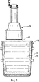
図1はベル及び溶融金属が充填されたトリベの静止状態における横断面図である。
図2はベル及び溶融金属が充填されたトリベの操作状態における横断面図である。
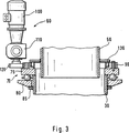
図3はベルを駆動させる装置の拡大図である。
耐熱性のライニング15を有するトリベ10は溶融鋼20で満たされ、溶融鋼20を処理するための耐熱性の筒状体すなわちベル30の下方に配置されている。操作位置においては、溶融金属の処理の間、べル30はその下端縁40が溶融鋼20に浸漬される位置まで降下される(図2)。
ベル30は供給パイプ50に連結されている。供給パイプ50を通じて、可燃性物質及び合金成分が溶融鋼20内に供給される。供給パイプ50は駆動装置60を有する。この駆動装置60はベルを駆動してそれを縦軸回りに回転させることができる。
不活性又は還元性の発泡ガスを溶融鋼20内に導入することができる。発泡ガスはトリベ10の底部に配置された多孔プラグ(図示せず)を通じて導入してもよいし、トリベ10内に導入されたランス(図示せず)を通じて導入してもよい。この発泡ガスはトリベ10内に貯留されている溶融鋼20の処理中にその鋼20を均質化するのに使用される。この発泡ガスは鋼20の表面に乱流を形成する。この乱流はベル30の局所摩耗、特に、ベル30の下端縁40の摩耗の原因となる。
図3はベル30を駆動させるための装置60の拡大図である。ベル30の上端部にはボールベアリング70が取り付けられている。ボールベアリング70は、ベル30をその縦軸回りに回転させることができるように、ベル30に対してしっかりと取り付けられている。ベアリング70の上部75はベル30に固定されているが、ベアリング70の下部80は回転自在となっている。ベアリング70に応力が加えられていない状態では、下部80はベアリング70の下方に位置するストッパ85に対して載置されている。もちろん、このベアリング70は汚染物が流入しないように保護される必要がある。
ベル30は取り付けシステム(図示せず)によって所定の位置に保持されている。この取り付けシステムはベアリング70の下部80を下方から押してベル30を供給パイプ50に押し付ける。ベル30の取り付けシステムには、たとえば、取り付けリップを設けることができる。
環状ギヤ90がベアリング70の上部75に設けられている。ベル30はモータ100によって回転させられる。なお、好ましくは、モータ100には減速ギヤ110が連結されており、ベル30の回転速度を変更できるように構成されている。モータ100はこのモータ100に固定されたギヤーホイール120を回転させ、このギヤーホイール120の回転を介して環状ギヤ90を回転させる。当然のことながら、このようなベルに回転動作を付与する手段としては、当業者であれば周知の他の手段もある。
供給パイプ50とベル30との間のシールはバッフル130によって形成されている。
ベル30及び供給パイプ50には耐熱材料で形成されたインナーライニングが設けられている。このライニングは図面の簡素化のために図示されていない。The present invention relates to a method and apparatus for treating molten metal in a ladle, in particular molten steel.
Currently, there are several methods for treating molten metal in a ladle, especially molten steel. According to these methods, a bell or a tube is introduced into the molten metal stored in the ladle. Such processing methods include in particular those known as CAS, CAS-OB, HALT, etc.
In this type of method, the molten metal stored in the ladle is subjected to different treatments in a restricted area limited by the bell introduced into the molten metal. Foaming gas is introduced into the molten metal from below the bell. This is to make it uniform during processing. As a result, a turbulent flow is generated on the surface of the molten metal, whereby local wear of the bell becomes apparent at the lower edge.
It is an object of the present invention to provide a method and apparatus that can minimize bell local wear during the processing of molten metal in a ladle.
The purpose is to minimize the local wear of the bell during the processing of the molten metal in the ladle so that the bell rotates around a predetermined axis during the processing of the molten metal. This is achieved by the structured method.
The fact that the bell is imparted with rotational movement allows the bell's local wear to be minimized. In fact, since the bell rotates during the processing of the molten metal, the possibility of local wear occurring at a predetermined position due to turbulent flow in the molten metal is eliminated. The bell actually wears uniformly over its entire periphery.
In addition to the expensiveness of such bells, the method of the present invention also contributes to a reduction in the running cost of the device, since replacing worn bells takes a considerable amount of time.
Such a method is particularly useful when carrying out the method for treating molten metal in a ladle disclosed in EP 0110809. In such a method, the steel stored in the ladle is heated by an aluminothermy method, and a predetermined number of alloy elements are added to the steel. The bell is stressed asymmetrically,
-On the "high temperature" side, the bell, more precisely the heat-resistant lining of the lower edge of the bell, is subjected to thermal shock and is subject to chemical corrosion due to metal and slag bounce. The cause of wear is mainly pulverization of the heat-resistant lining.
-On the "cold" side, perhaps the case where the refractory lining is cooled in intermittent use, the bell is "thickened" by solidification of the metal and / or slag bounce.
These phenomena, such as local wear and “thickening”, significantly shorten the service life of the bell, and thus increase the production cost of methods involving addition and heating using the bell. According to the proposed method, the heat resistance is reduced by minimizing local “thickening” by minimizing local wear and by compensating for local wear by the lining produced during use. The service life of the bell has been extended.
According to the first embodiment, the rotational speed of the bell during the processing of the molten metal is between 0.5 and 2 revolutions per minute. The rotational speed of the bell can be set as a function of the bell diameter, as a function of the treatment applied to the molten metal, and / or as a function of the composition and viscosity of the slag covering the molten metal in the ladle. Needless to say, the ladle can be continuously rotated around its axis, and the rotation can be continued even when the processing of the molten metal is completed and the ladle is taken out from the bath.
According to another embodiment, the bell is rotated about a longitudinal axis substantially perpendicular to the surface of the molten metal or steel.
In another embodiment, an apparatus for carrying out the method is also proposed. This device has a drive device for rotationally driving the bell during processing of molten metal.
Preferred embodiments of the device according to the invention will be described with reference to the accompanying drawings.
FIG. 1 is a cross-sectional view in a stationary state of a bell and a ladle filled with molten metal.
FIG. 2 is a cross-sectional view in the operating state of the bell and the ladle filled with molten metal.
FIG. 3 is an enlarged view of a device for driving the bell.
The
The
An inert or reducing foaming gas can be introduced into the
FIG. 3 is an enlarged view of a
The
An
The seal between the
The
Claims (4)
Applications Claiming Priority (3)
| Application Number | Priority Date | Filing Date | Title |
|---|---|---|---|
| LU90005 | 1997-01-15 | ||
| LU90005A LU90005B1 (en) | 1997-01-15 | 1997-01-15 | Method and installation for the treatment of acer in a pocket |
| PCT/EP1998/000044 WO1998031841A1 (en) | 1997-01-15 | 1998-01-07 | Method and installation for ladle treatment of steel |
Publications (2)
| Publication Number | Publication Date |
|---|---|
| JP2001508132A JP2001508132A (en) | 2001-06-19 |
| JP4201214B2 true JP4201214B2 (en) | 2008-12-24 |
Family
ID=19731652
Family Applications (1)
| Application Number | Title | Priority Date | Filing Date |
|---|---|---|---|
| JP53361298A Expired - Lifetime JP4201214B2 (en) | 1997-01-15 | 1998-01-07 | Method and apparatus for ladle treatment of steel |
Country Status (12)
| Country | Link |
|---|---|
| US (1) | US6413469B1 (en) |
| EP (1) | EP0954615B1 (en) |
| JP (1) | JP4201214B2 (en) |
| AT (1) | ATE206471T1 (en) |
| AU (1) | AU717378B2 (en) |
| BR (1) | BR9806315A (en) |
| CA (1) | CA2274009C (en) |
| DE (1) | DE69801895T2 (en) |
| LU (1) | LU90005B1 (en) |
| RU (1) | RU2205879C2 (en) |
| UA (1) | UA61095C2 (en) |
| WO (1) | WO1998031841A1 (en) |
Families Citing this family (2)
| Publication number | Priority date | Publication date | Assignee | Title |
|---|---|---|---|---|
| US7767698B2 (en) | 2002-06-03 | 2010-08-03 | Mcneil Ab | Formulation and use thereof |
| EP1568790A1 (en) * | 2004-02-24 | 2005-08-31 | Paul Wurth S.A. | Apparatus for the treatment of liquid metal in a ladle |
Family Cites Families (11)
| Publication number | Priority date | Publication date | Assignee | Title |
|---|---|---|---|---|
| US1942202A (en) * | 1931-04-25 | 1934-01-02 | Ralph F Cohn | Rotator |
| DE1190479B (en) * | 1960-07-07 | 1965-04-08 | Jan Erik Oestberg | Device for accelerating physicochemical processes in metal melts |
| GB1187168A (en) * | 1967-10-24 | 1970-04-08 | Standard Messo Duisburg | Improvements in or relating to the Production of Steel. |
| DE2261138C3 (en) | 1972-12-14 | 1975-05-15 | Polysius Ag, 4723 Neubeckum | Process for introducing aggregates into a metallurgical bath |
| SU609591A1 (en) * | 1976-07-08 | 1978-06-05 | Научно-производственное объединение "Тулачермет" | Device for stirring metal in open-ended mould |
| DE2707726A1 (en) * | 1977-02-23 | 1978-08-31 | Kloeckner Humboldt Deutz Ag | DEVICE FOR SEPARATING A MIXTURE OF COMPONENTS, IN PARTICULAR MOLTEN METALS, METAL COMPOUNDS AND / OR METALLIC SLAGS IN A CENTRIFUGAL FIELD |
| CH656399A5 (en) * | 1981-05-08 | 1986-06-30 | Fischer Ag Georg | DIVE EVAPORATION CHAMBER. |
| LU84472A1 (en) * | 1982-11-17 | 1984-06-13 | Arbed | PROCESS AND PLANT FOR THE TREATMENT OF POCKET STEEL |
| NO155447C (en) * | 1984-01-25 | 1987-04-01 | Ardal Og Sunndal Verk | DEVICE FOR PLANT FOR TREATMENT OF A FLUID, E.g. AN ALUMINUM MELT. |
| DE4234973C1 (en) * | 1992-10-16 | 1994-06-01 | Tech Resources Pty Ltd | Process for protecting the refractory lining in the gas space of metallurgical reaction vessels |
| NO176553C (en) * | 1993-04-14 | 1995-04-26 | Norsk Hydro As | injection equipment |
-
1997
- 1997-01-15 LU LU90005A patent/LU90005B1/en active
-
1998
- 1998-01-07 AU AU58620/98A patent/AU717378B2/en not_active Ceased
- 1998-01-07 WO PCT/EP1998/000044 patent/WO1998031841A1/en not_active Ceased
- 1998-01-07 BR BR9806315-4A patent/BR9806315A/en not_active IP Right Cessation
- 1998-01-07 US US09/341,636 patent/US6413469B1/en not_active Expired - Fee Related
- 1998-01-07 JP JP53361298A patent/JP4201214B2/en not_active Expired - Lifetime
- 1998-01-07 DE DE69801895T patent/DE69801895T2/en not_active Expired - Lifetime
- 1998-01-07 AT AT98901944T patent/ATE206471T1/en active
- 1998-01-07 EP EP98901944A patent/EP0954615B1/en not_active Expired - Lifetime
- 1998-01-07 CA CA002274009A patent/CA2274009C/en not_active Expired - Fee Related
- 1998-01-07 RU RU99117542/02A patent/RU2205879C2/en not_active IP Right Cessation
- 1998-07-01 UA UA99084660A patent/UA61095C2/en unknown
Also Published As
| Publication number | Publication date |
|---|---|
| UA61095C2 (en) | 2003-11-17 |
| US6413469B1 (en) | 2002-07-02 |
| LU90005B1 (en) | 1998-07-16 |
| CA2274009A1 (en) | 1998-07-23 |
| RU2205879C2 (en) | 2003-06-10 |
| EP0954615B1 (en) | 2001-10-04 |
| AU5862098A (en) | 1998-08-07 |
| BR9806315A (en) | 2000-03-14 |
| CA2274009C (en) | 2007-05-01 |
| DE69801895T2 (en) | 2002-04-25 |
| JP2001508132A (en) | 2001-06-19 |
| WO1998031841A1 (en) | 1998-07-23 |
| EP0954615A1 (en) | 1999-11-10 |
| ATE206471T1 (en) | 2001-10-15 |
| DE69801895D1 (en) | 2001-11-08 |
| AU717378B2 (en) | 2000-03-23 |
Similar Documents
| Publication | Publication Date | Title |
|---|---|---|
| JPH06504358A (en) | Rotary tube heat treatment equipment, in particular rotary tube furnaces with indirect heat introduction or heat extraction | |
| US6413469B1 (en) | Method and installation for ladle treatment of steel | |
| ES467377A1 (en) | Process and installation for heat treating spheroidal or lamellar graphite cast iron pipes | |
| KR100325696B1 (en) | casting machine of turntable type and casting method of the same | |
| EP1480735B1 (en) | Sealed impeller for producing metal foam and system | |
| GB2141955A (en) | Method and apparatus for continuously treating molten metal | |
| JP4010346B2 (en) | Method of induction hardening the inner peripheral surface of a member having an unequal thickness | |
| JPH10113753A (en) | Rotary immersion nozzle | |
| JP2564583B2 (en) | Raw material charging device for electric melting furnace | |
| JP3431597B2 (en) | Degassing method and molten steel stirrer in simple degassing equipment for molten steel | |
| JP2008231521A (en) | Die for centrifugal casting | |
| RU99117542A (en) | METHOD AND INSTALLATION FOR PROCESSING STEEL IN A DUCK | |
| JPH11304375A (en) | Exhaust pipe blockage prevention device | |
| RU1799921C (en) | Method for gear thermal treating | |
| RU2016911C1 (en) | Method and apparatus for preparation of aluminum alloys | |
| JPS62205236A (en) | Contact member with molten metal | |
| JPS6236055Y2 (en) | ||
| SU1044638A2 (en) | Method for carburizing melt | |
| RU2066690C1 (en) | Apparatus for bottom blowing of metal | |
| JP3113143B2 (en) | Manufacturing method of hot-dip aluminized steel sheet | |
| KR880003020A (en) | Silicon Purification Method and Apparatus | |
| JPS6330157A (en) | Cooling drum type strip continuous casting method | |
| JPS5946708B2 (en) | Overlay welding method for thin-walled metal tubes | |
| JPH11100620A5 (en) | ||
| JPS62258986A (en) | Contacting member with molten metal |
Legal Events
| Date | Code | Title | Description |
|---|---|---|---|
| A621 | Written request for application examination |
Free format text: JAPANESE INTERMEDIATE CODE: A621 Effective date: 20040720 |
|
| A711 | Notification of change in applicant |
Free format text: JAPANESE INTERMEDIATE CODE: A711 Effective date: 20060920 |
|
| A521 | Request for written amendment filed |
Free format text: JAPANESE INTERMEDIATE CODE: A523 Effective date: 20061127 |
|
| A131 | Notification of reasons for refusal |
Free format text: JAPANESE INTERMEDIATE CODE: A131 Effective date: 20071113 |
|
| A601 | Written request for extension of time |
Free format text: JAPANESE INTERMEDIATE CODE: A601 Effective date: 20080213 |
|
| A521 | Request for written amendment filed |
Free format text: JAPANESE INTERMEDIATE CODE: A523 Effective date: 20080227 |
|
| A131 | Notification of reasons for refusal |
Free format text: JAPANESE INTERMEDIATE CODE: A131 Effective date: 20080708 |
|
| A521 | Request for written amendment filed |
Free format text: JAPANESE INTERMEDIATE CODE: A523 Effective date: 20080807 |
|
| TRDD | Decision of grant or rejection written | ||
| A01 | Written decision to grant a patent or to grant a registration (utility model) |
Free format text: JAPANESE INTERMEDIATE CODE: A01 Effective date: 20080930 |
|
| A01 | Written decision to grant a patent or to grant a registration (utility model) |
Free format text: JAPANESE INTERMEDIATE CODE: A01 |
|
| A61 | First payment of annual fees (during grant procedure) |
Free format text: JAPANESE INTERMEDIATE CODE: A61 Effective date: 20081003 |
|
| R150 | Certificate of patent or registration of utility model |
Free format text: JAPANESE INTERMEDIATE CODE: R150 |
|
| FPAY | Renewal fee payment (event date is renewal date of database) |
Free format text: PAYMENT UNTIL: 20111017 Year of fee payment: 3 |
|
| FPAY | Renewal fee payment (event date is renewal date of database) |
Free format text: PAYMENT UNTIL: 20121017 Year of fee payment: 4 |
|
| FPAY | Renewal fee payment (event date is renewal date of database) |
Free format text: PAYMENT UNTIL: 20131017 Year of fee payment: 5 |
|
| R250 | Receipt of annual fees |
Free format text: JAPANESE INTERMEDIATE CODE: R250 |
|
| R250 | Receipt of annual fees |
Free format text: JAPANESE INTERMEDIATE CODE: R250 |
|
| R250 | Receipt of annual fees |
Free format text: JAPANESE INTERMEDIATE CODE: R250 |
|
| R250 | Receipt of annual fees |
Free format text: JAPANESE INTERMEDIATE CODE: R250 |
|
| R250 | Receipt of annual fees |
Free format text: JAPANESE INTERMEDIATE CODE: R250 |
|
| EXPY | Cancellation because of completion of term |