JP4201569B2 - Luggage loading locker of automatic locker device for luggage etc. - Google Patents
Luggage loading locker of automatic locker device for luggage etc. Download PDFInfo
- Publication number
- JP4201569B2 JP4201569B2 JP2002305838A JP2002305838A JP4201569B2 JP 4201569 B2 JP4201569 B2 JP 4201569B2 JP 2002305838 A JP2002305838 A JP 2002305838A JP 2002305838 A JP2002305838 A JP 2002305838A JP 4201569 B2 JP4201569 B2 JP 4201569B2
- Authority
- JP
- Japan
- Prior art keywords
- luggage
- locker
- collection
- guide plate
- automatic management
- Prior art date
- Legal status (The legal status is an assumption and is not a legal conclusion. Google has not performed a legal analysis and makes no representation as to the accuracy of the status listed.)
- Expired - Fee Related
Links
Images




Landscapes
- Supports Or Holders For Household Use (AREA)
Description
【0001】
【発明の属する技術分野】
本発明は荷物等自動管理ロッカー装置と併設され、クリーニング品などの集荷物が投入される集荷物投入ロッカーにおいて、特に店舗の営業時間帯にはバックヤード(従業員専用スペース)から集荷物の回収を可能とし、営業時間外にはロッカー内に集荷物を貯蔵可能とした集荷物投入ロッカーに関する。
【0002】
【従来の技術】
マンション等の共同住宅のエントランス部分などに設置され、宅配物の自動受け渡しを可能とする荷物等自動管理ロッカー装置は、従来から広く使用されている。また荷物等自動管理ロッカー装置には、クリーニング品や写真フィルムなどを回収する集荷物投入ロッカーを併設して、クリーニングやDPEなどのサービスによって付加価値を向上させることも一般的に行なわれている。
【0003】
出願人は、このような荷物等自動管理ロッカー装置について、既に特願2001−295329を出願している。この出願には、制御部によって施錠が制御された洗濯物等の出荷用ロッカーが開示されており、顧客が上段ロッカーの前面扉から投入した洗濯物を、集配業者が下段ロッカーの前面扉を開けて集荷する構造となっている。
【0004】
上記の集荷物投入ロッカーは店舗の一角に設置して無人で運用することを想定したもので、次の問題点を有している。
(1)集荷物をロッカー内に大量に溜め込むことができない。
(2)ロッカーの運用効率を高めるためには、集荷物を定期的あるいは頻繁に回収しなければならない。
(3)集荷物回収のための開口が前面に設置され、かつ扉が前開きであるため、集荷物回収時に扉を開くと店舗内のスペースを取り、また回収時にはロッカー前が集荷物で雑然とする。
(4)近時、図2のような店舗設計において、昼間には従業員を配置するが、夜間は無人でロッカーを使用する運用が要望されている。しかし、この場合に回収のためのロッカー開口を前面側に設けた構造にすると、前記(1)(2)(3)の問題が解決しない。更に、顧客と従業員がロッカー前で交錯するため、両者ともに作業性が悪い。
(5)前項の店舗設計で運用する場合、以上の問題を解決し且つ夜間の無人状態におけるバックヤードの防犯性を確保できるロッカーは従来存在しなかった。ここで防犯性とは、ロッカーの開口からバックヤードに危険物を投入したり、開口からの進入等を出来難くすることである。
【0005】
【特許文献1】
特願2001−295329 明細書
【0006】
【発明が解決しようとする課題】
本発明は前記従来技術の欠点を除くためにされたものであり、その目的は、通常の営業時間帯にバックヤードから集荷物の回収を可能とすることで、▲1▼ロッカー内に集荷物を溜め込むことなく、▲2▼集荷物回収の手間を抑え、▲3▼回収時の作業性を向上させた集荷物投入ロッカーを提供することである。
【0007】
また本発明の他の目的は、夜間の無人状態におけるロッカーの運用にも対応し、かつ夜間の無人状態におけるバックヤードの防犯性を確保できる集荷物投入ロッカーを提供することである。
【0008】
【課題を解決するための手段】
(1) 第1の発明は、仕切り壁2と一体となって店舗スペース3とバックヤード4(従業員専用スペース)とを区画する集荷物投入ロッカー1であって、店舗スペース3に面した前記集荷物投入ロッカー1正面の集荷物投入口6には、前記店舗スペース3内に配置された荷物等自動管理ロッカー装置10の制御部10aによって施錠が制御される投入口扉9が設けられ、バックヤード4側に面した前記集荷物投入ロッカー1背面には前記集荷物投入口6と連通する集荷物取出口11が開口され、前記集荷物投入ロッカー1の内部には前記集荷物取出口11を閉鎖可能なガイド板13が配置され、前記ガイド板13は、一辺を前記集荷物取出口11の下縁部近傍に配置し、他の一辺を集荷物投入ロッカー1内において投入口6側の斜め上方に向けて配置した傾斜配置が可能であって、
前記集荷物投入ロッカー1は、(i)前記ガイド板13を前記集荷物投入ロッカー背面側に直立状態として前記ガイド板13で集荷物取出口11を閉鎖してロッカー1内部に集荷物8を貯蔵可能とした状態と、(ii)前記ガイド板13の前記他の一辺を前記集荷物投入ロッカー正面の集荷物投入口6の下方において投入口側の斜め上方に向けて前記ガイド板13を傾斜配置し、前記ガイド板13によって前記集荷物8を前記集荷物取出口11に誘導して前記バックヤード4側に排出可能とした状態、の2つの状態を選択可能であることを特徴とする荷物等自動管理ロッカー装置10の集荷物投入ロッカー1である。
(2) 第2の発明は、第1の発明において、ガイド板13の一辺が前記集荷物取出口11の下縁部近傍に設けられたヒンジ14によって開閉可能に支持されてなることを特徴とする。
(3) 第3の発明は、第1または第2の発明において、集荷物投入ロッカー1の内部に集荷物投入量の感知手段15を設けたことを特徴とする。
(4) 第4の発明は、第1から第3のいずれかの発明において、集荷物投入口6の下側には折り返し部5aを有する仕切り板5が設けられていることを特徴とする。
(5) 第5の発明は、第1から第4のいずれかの発明において、集荷物投入ロッカー1の内部に、集荷物貯蔵部7と独立したDPE回収部16が設けられていることを特徴とする。
【0009】
なお、本明細書における「仕切り壁」は、バックヤードとロッカースペースとを実質的に仕切るものであればよく、壁であることは要さない。例えば、パーテーション、シャッター、収納棚、ショーケース等も本発明の仕切り壁として想定される。
【0010】
【発明の実施の形態】
<第1実施形態>
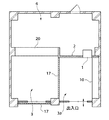
以下、本発明の集荷物投入ロッカーの第1実施形態について、図面を参照しつつ説明する。図1および図2に示すように、本発明の集荷物投入ロッカー1は仕切り壁2と一体となって店舗スペース3とバックヤード(従業員専用スペース)4とを区画しており、ロッカー1の正面側が店舗スペース3に面し、かつ背面側がバックヤード4に面する状態で設置される。図2の符号17はシャッターであり、昼間従業員が居る時は開かれ、店舗スペース(3および3a)は1つの連続した空間を形成している。一方、従業員のいない夜間などの時間帯には、シャッター17が閉じられて、出入り口以外ロッカースペース3aは閉ざされた空間となる。
【0011】
次に第1実施形態の集荷物投入ロッカー1の構造について述べる。第1実施形態の集荷物投入ロッカー1は中空の長方形箱体であって、ロッカー1内部が正面側手前に設けられた仕切り板5によって上下に区画され、仕切り板の上側が集荷物投入口6となり、仕切り板の下側が集荷物貯蔵部7となっている。集荷物投入口6と集荷物貯蔵部7とは仕切り板5の奥に位置する開口部で連通しており、集荷物投入口6から投入した集荷物8は集荷物貯蔵部7に向けて落下するようになっている。なお仕切り板5の端部には折り返し部5aが形成されており、投入した集荷物8が集荷物投入口6から取り出せないように構成されている。
【0012】
集荷物投入口6の正面側には電気錠が取り付けられた投入口扉9が取り付けられている。この投入口扉9の施錠・開錠は、荷物等自動管理ロッカー装置10の制御部10aによって制御されており、荷物等自動管理ロッカー装置10を利用できる顧客以外は開閉できないようになっている。
【0013】
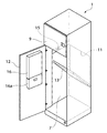
また集荷物貯蔵部7の背面側には集荷物取出口11が開口されており、バックヤード4から集荷物8が取り出せるように構成されている。一方、集荷物貯蔵部7の正面側には専用錠を備えた下側扉12が取り付けられており、鍵を有する従業員が下側扉12を開放することによって溜め込まれた集荷物8をロッカー1正面からも回収できるようになっている。
【0014】
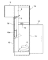
さらに、集荷物貯蔵部7の内部には前記集荷物取出口11を閉鎖可能な矩形のガイド板13が配置されている。このガイド板13の一辺は集荷物取出口11の下縁部近傍に設けられたヒンジ14に連結されており、集荷物取出口11を開閉動可能なようにロッカー1内でピン支持されている。またこのガイド板13は、他の一辺を投入口側斜め上方に向けた傾斜状態で固定できるように構成されている。
【0015】
すなわち、ガイド板13はロッカー1内において、前記の傾斜状態と、集荷物取出口11に沿った直立状態との2つの位置で固定することができる。そして、ガイド板13が前記傾斜状態の場合には、集荷物投入口6から投入された集荷物8はガイド板13を滑り降りて集荷物取出口11を通過し、バックヤード4に排出される。一方、ガイド板13が前記直立状態の場合には集荷物取出口11がガイド板13によって閉鎖され、集荷物投入口6から投入された集荷物8は集荷物貯蔵部7に溜め込まれる。なお、ガイド板13を直立状態にして荷物取出口を閉じた場合、ロックしてガイド板が棒等によって簡単に押し開けられないようにすることが好ましい[図示を省略する]。これによって防犯性を確保することができる。
【0016】
また、集荷物貯蔵部7の上側には集荷物投入量の感知手段15が設けられており、集荷物が感知手段15の取り付け位置まで到達したか否か(ロッカー1内の集荷物8が満杯か否か)が判断できるように構成されている。そして、ロッカー1内の集荷物8が満杯の場合には、感知手段15は荷物等自動管理ロッカー装置10の制御部10aに信号を出力することで該制御部10aが投入口扉9を開錠不可の状態とし、これ以上の集荷物8の投入ができないようにすることができる。なお、感知手段15は、例えば、発光素子と受光素子とを組み合わせた光学センサや、マイクロスイッチなどの公知のセンサを適宜用いて構成される。
【0017】
さらに、集荷物投入ロッカー1の内部には集荷物貯蔵部7と独立したDPE回収部16が設けられている。このDPE回収部16は下側扉12の裏面にコ字形側板を取り付けて、受け底16aを分割して回転可能に構成したものである。またDPE回収部16の上側に位置する仕切り板5には、写真フィルムを入れた袋を投入可能なDPE投入口が設けられており、このDPE投入口には回転蓋5bが取り付けられている。なお、DPE回収部16の構成は上記に限定されることなく、例えば回収袋を仕切り板のDPE投入口の下に取り付けるなど、適宜変更することができる。
【0018】
本発明の集荷物投入ロッカー1は上記のように構成されており、以下その運用を洗濯物の集荷を例として説明する。図1、図2は、本発明の集荷物投入ロッカー1および荷物等自動管理ロッカー装置10を設置した店舗の参考図である。店舗内は顧客が出入りする店舗スペース3と、従業員のみ通行可能なバックヤード4とに大別されている。また店舗スペース3は、夜間などの従業員がいない無人状態でも顧客が出入りできるロッカースペース3aと、直接従業員がカウンター20で受け付けるスペースとがシャッター17等で区画できるようになっており、店舗の営業時間外においても集荷物8の投入が可能となっている。
【0019】
本発明の集荷物投入ロッカー1は、荷物等自動管理ロッカー装置10と一体となって運用され、集荷物投入ロッカー1および荷物等自動管理ロッカー装置10は、店舗スペース3の一部であるロッカースペース3aに設置されている。そして、集荷物投入ロッカー1は仕切り壁2と一体となってロッカースペース3aとバックヤード4とを区画している。集荷物投入ロッカー1は、正面側がロッカースペース3aに面し、かつ背面側がバックヤード4に面する状態で店舗内に設置される。
【0020】
顧客が集荷物投入ロッカー1を利用しようとする場合、顧客は予め所定事項(氏名、住所、登録番号、洗濯物の種類、材質など)を記入したラベルを貼った集荷バック8に洗濯物を詰め込んでおく。
【0021】
そして顧客は荷物等自動管理ロッカー装置10の制御部10aに設けられたタッチパネル10bを操作して、会員認証等を行なった後に集荷物投入ロッカー1の投入口扉9の開錠動作を行なう。荷物等自動管理ロッカー装置10の制御部10aは、集荷物貯蔵部7の感知手段15からの信号入力がない場合(ロッカー1内が満杯ではない場合)には、投入口扉9の電気錠を開錠する信号を出力する。これにより顧客は投入口扉9を手動で開けて、集荷物投入口6から集荷バック8を投入することができる。
【0022】
また従業員のいる時間帯には、集荷物投入ロッカー1のガイド板13は傾斜状態で配置され、集荷物投入口6から投入された集荷バック8はガイド板13を滑り降りて集荷物取出口11を通過し、バックヤード4に用意された台車18などに排出される。したがって、集荷物8は集荷物貯蔵部7に溜め込まれることなく、集荷物投入ロッカー1の効率的な運用を図ることができる。
【0023】
一方、夜間など従業員がいない時間帯には、ロッカースペース3aのみ顧客が出入りできるようにシャッター17等で店舗スペース3内が区画される。そして集荷物投入ロッカー1のガイド板13は直立状態で配置されて集荷物取出口11が閉鎖され、集荷物投入口6から投入された集荷バック8はロッカー1内の集荷物貯蔵部7に溜め込まれる。なお、ロッカー1内が集荷バック8で満杯になった場合には、ロッカー1内の集荷物投入量感知手段15が信号を出力し、荷物等自動管理ロッカー装置10の制御部10aが投入口扉9を開錠不可の状態にして集荷物8の投入はできないようになる。
【0024】
そして、集荷バック8内の洗濯物は業者によってクリーニングされた後に荷物等自動管理ロッカー装置10に配達される。顧客は、荷物等自動管理ロッカー装置10のタッチパネル10bを操作して認証作業を行い、受け取りメニューを選択する。そして、顧客は洗濯物(仕上がり品)が収納された所定のロッカーを開錠し、クリーニングされた洗濯物を受け取る。なお、顧客が仕上がり品を受け取った旨の情報は、荷物等自動管理ロッカー装置10の制御部から管理者のデータベースに送信される[図7参照]。
【0025】
<参考形態>
図6は、参考形態の集荷物投入ロッカー1aを示した図である。参考形態の集荷物投入ロッカー1aは集荷物取出口11を背面扉19によって閉鎖する構成であり、ロッカー内にガイド板13が設けられていない点で第1実施形態と異なる。また参考形態では、集荷物投入ロッカー1正面側の下側扉12を設けることなく、常時バックヤード4側から集荷物8を回収するようにしてもよい。なお、参考形態で第1実施形態と同一の構成には同一符号を付して重複説明を省略する。
【0026】
以上、本発明の集荷物投入ロッカーを図示の実施形態に基いて説明してきたが、本発明の特許請求の範囲は前記実施形態に限定されるものではない。例えば、第1実施形態の集荷物投入ロッカーにおいて、ガイド板をヒンジで連結することなく独立させて、ロッカー内に設けた挿入溝にガイド板を差し込んで傾斜状態と直立状態とを選択できるようにしてもよい[図示を省略する]。また、本発明の集荷物は洗濯物に限定されることなく、レンタルビデオ、図書などの集荷に利用することも可能である。
【0027】
【発明の効果】
本発明の集荷物投入ロッカーは、通常の営業時間帯にバックヤードから集荷物の回収を可能としたことにより、▲1▼ロッカー内に集荷物を溜め込むことなく、▲2▼集荷物回収の手間を抑え、▲3▼回収時の作業性が向上するという効果を奏する。
【0028】
また本発明の集荷物投入ロッカーは、夜間の無人状態におけるロッカーの運用にも対応し、かつ夜間の無人状態におけるバックヤードの防犯性を確保できる。
【図面の簡単な説明】
【図1】 集荷物投入ロッカーおよび荷物等自動管理ロッカー装置を配置した店舗の様子を示した参考斜視図である。
【図2】 図1に対応する店舗間取図である。
【図3】 (a)は第1実施形態の集荷物投入ロッカーの正面図であって、(b)はその背面図である。
【図4】 第1実施形態の集荷物投入ロッカーの下側扉を開けた状態の斜視図である。
【図5】 (a)は第1実施形態の集荷物投入ロッカーにおけるガイド板の傾斜状態を示す側面図であり、(b)はガイド板の直立状態を示す側面図である。
【図6】 参考形態の集荷物投入ロッカーの側面図である。
【図7】 洗濯物の仕上がり品受取時の状況を示すフローチャートである。
【符号の説明】
1,1a 集荷物投入ロッカー
2 仕切り壁
3 店舗スペース
3a ロッカースペース
4 バックヤード(従業員専用スペース)
5 仕切り板
5a 折り返し部
5b 回転蓋
6 集荷物投入口
7 集荷物貯蔵部
8 集荷物(集荷バック)
9 投入口扉
10 荷物等自動管理ロッカー装置
10a 制御部
10b タッチパネル
11 集荷物取出口
12 下側扉
13 ガイド板
14 ヒンジ
15 集荷物投入量感知手段
16 DPE回収部
16a 受け底
17 シャッター
18 台車
19 背面扉
20 カウンター[0001]
BACKGROUND OF THE INVENTION
The present invention is a luggage collection locker that is provided with an automatic management locker device for luggage, etc., and that collects luggage such as cleaning items, and collects luggage from the backyard (employee dedicated space) especially during store hours. The present invention relates to a luggage collection locker that can store luggage in the locker outside business hours.
[0002]
[Prior art]
2. Description of the Related Art An automatic luggage locker device that is installed at the entrance of a condominium, such as a condominium, and enables automatic delivery of parcels has been widely used. In addition, a load collection locker that collects cleaning products, photographic films, and the like is also provided in the automatic management locker device for luggage and the like, and it is generally performed to increase added value by services such as cleaning and DPE.
[0003]
The applicant has already filed Japanese Patent Application No. 2001-295329 for such an automatic management locker device for luggage and the like. This application discloses a locker for shipping such as laundry whose locking is controlled by the control unit, and the collection / delivery company opens the front door of the lower locker after the customer puts the laundry put in from the front door of the upper locker. It is structured to collect.
[0004]
The above luggage collection locker is assumed to be installed in a corner of a store and operated unattended, and has the following problems.
(1) A large amount of luggage cannot be stored in the locker.
(2) In order to increase the operational efficiency of lockers, the collected luggage must be collected regularly or frequently.
(3) Since the opening for collecting luggage is installed on the front and the door is opened forward, opening the door when collecting luggage collects space in the store. And
(4) Recently, in the store design as shown in FIG. 2, employees are arranged in the daytime, but there is a demand for an operation that uses no lockers at night. However, in this case, if the structure is provided with a rocker opening for recovery on the front side, the problems (1), (2) and (3) cannot be solved. Furthermore, since the customer and the employee cross together in front of the locker, both of them have poor workability.
(5) When operating in the store design of the previous paragraph, there has been no locker that can solve the above problems and can secure the security of the backyard in the unattended state at night. Here, crime prevention means that a dangerous substance is thrown into the backyard from the opening of the locker, and it is difficult to enter from the opening.
[0005]
[Patent Document 1]
Japanese Patent Application No. 2001-295329 Specification [0006]
[Problems to be solved by the invention]
The present invention has been made to eliminate the disadvantages of the prior art, and its purpose is to enable collection of luggage from the backyard during normal business hours, so that (1) luggage collection in the locker. (2) To provide a load collection locker that improves the workability at the time of collection.
[0007]
Another object of the present invention is to provide a load-carrying locker that can cope with the operation of a locker in an unattended state at night and can secure crime prevention of a backyard in an unattended state at night.
[0008]
[Means for Solving the Problems]
(1) 1st invention is the
The load collection locker 1 (i) stores the
(2) The second invention is characterized in that, in the first invention, one side of the
(3) The third invention is characterized in that, in the first or second invention, the cargo collection input amount detecting means 15 is provided inside the
( 4 ) The fourth invention is characterized in that, in any one of the first to third inventions, a
( 5 ) The fifth invention is characterized in that, in any one of the first to fourth inventions, a
[0009]
Note that the “partition wall” in the present specification is not limited to a wall as long as it substantially partitions the backyard and the locker space. For example, a partition, a shutter, a storage shelf, a showcase, and the like are also assumed as the partition wall of the present invention.
[0010]
DETAILED DESCRIPTION OF THE INVENTION
<First Embodiment>
Hereinafter, a first embodiment of a luggage collection locker according to the present invention will be described with reference to the drawings. As shown in FIGS. 1 and 2, the
[0011]
Next, the structure of the
[0012]
An
[0013]
In addition, a
[0014]
Further, a
[0015]
That is, the
[0016]
Also, a cargo collection
[0017]
Further, a
[0018]
The
[0019]
The
[0020]
When the customer intends to use the
[0021]
Then, the customer operates the
[0022]
Also, during the time when employees are present, the
[0023]
On the other hand, in the time zone when there are no employees such as at night, the
[0024]
Then, the laundry in the
[0025]
< Reference form>
FIG. 6 is a view showing a
[0026]
As mentioned above, although the luggage collection locker of this invention has been demonstrated based on embodiment of illustration, the claim of this invention is not limited to the said embodiment. For example, in the luggage collection locker of the first embodiment, the guide plate is made independent without being connected by a hinge, and the guide plate is inserted into the insertion groove provided in the locker so that the inclined state or the upright state can be selected. [The illustration is omitted]. Further, the luggage collection of the present invention is not limited to laundry, but can be used for collecting rental videos, books, and the like.
[0027]
【The invention's effect】
The luggage collection locker according to the present invention enables collection of luggage from the backyard during normal business hours. (1) No need to collect luggage in the locker. (3) The workability during collection is improved.
[0028]
In addition, the luggage collection locker according to the present invention can cope with the operation of the locker in the unattended state at night, and can secure the security of the backyard in the unattended state at night.
[Brief description of the drawings]
FIG. 1 is a reference perspective view showing a state of a store where a load collection locker and an automatic management locker device for luggage etc. are arranged.
FIG. 2 is a store floor plan corresponding to FIG. 1;
FIG. 3A is a front view of the luggage collection locker according to the first embodiment, and FIG. 3B is a rear view thereof.
FIG. 4 is a perspective view showing a state in which a lower door of the luggage collection locker according to the first embodiment is opened.
5A is a side view showing the inclined state of the guide plate in the luggage loading locker of the first embodiment, and FIG. 5B is a side view showing the upright state of the guide plate.
FIG. 6 is a side view of a load collection locker of a reference form.
FIG. 7 is a flowchart showing a situation when a laundry finished product is received.
[Explanation of symbols]
1,1a
5
Claims (5)
前記集荷物投入ロッカーは、(i)前記ガイド板を前記集荷物投入ロッカー背面側に直立状態として前記ガイド板で集荷物取出口を閉鎖してロッカー内部に集荷物を貯蔵可能とした状態と、(ii)前記ガイド板の前記他の一辺を前記集荷物投入ロッカー正面の集荷物投入口の下方において投入口側の斜め上方に向けて前記ガイド板を傾斜配置し、前記ガイド板によって前記集荷物を前記集荷物取出口に誘導して前記バックヤード側に排出可能とした状態、の2つの状態を選択可能であることを特徴とする荷物等自動管理ロッカー装置の集荷物投入ロッカー。A luggage collection locker that divides a store space and a backyard together with a partition wall, and is disposed in the store space at a luggage input port in front of the luggage input locker facing the store space. An entrance door whose locking is controlled by the control unit of the automatic management locker device is provided, and on the back side of the luggage input locker facing the backyard side, there is a luggage collection outlet communicating with the luggage entrance. A guide plate capable of closing the luggage collection outlet is disposed inside the luggage collection locker, and the guide plate is disposed on one side in the vicinity of the lower edge of the luggage collection outlet. An inclined arrangement in which one side is arranged obliquely upward on the loading port side in the luggage collection locker is possible,
The luggage collection locker is (i) a state in which the guide plate is in an upright state on the back side of the luggage collection locker, the luggage collection opening is closed with the guide plate, and the luggage collection can be stored inside the locker; (Ii) The guide plate is disposed so that the other one side of the guide plate is inclined obliquely upward on the loading port side below the loading port on the front of the luggage loading locker. It is possible to select two states: a state in which the baggage can be discharged to the backyard side by guiding it to the baggage collection outlet, and a load collection locker for an automatic management locker device for luggage, etc.
Priority Applications (1)
| Application Number | Priority Date | Filing Date | Title |
|---|---|---|---|
| JP2002305838A JP4201569B2 (en) | 2002-10-21 | 2002-10-21 | Luggage loading locker of automatic locker device for luggage etc. |
Applications Claiming Priority (1)
| Application Number | Priority Date | Filing Date | Title |
|---|---|---|---|
| JP2002305838A JP4201569B2 (en) | 2002-10-21 | 2002-10-21 | Luggage loading locker of automatic locker device for luggage etc. |
Publications (2)
| Publication Number | Publication Date |
|---|---|
| JP2004136025A JP2004136025A (en) | 2004-05-13 |
| JP4201569B2 true JP4201569B2 (en) | 2008-12-24 |
Family
ID=32452829
Family Applications (1)
| Application Number | Title | Priority Date | Filing Date |
|---|---|---|---|
| JP2002305838A Expired - Fee Related JP4201569B2 (en) | 2002-10-21 | 2002-10-21 | Luggage loading locker of automatic locker device for luggage etc. |
Country Status (1)
| Country | Link |
|---|---|
| JP (1) | JP4201569B2 (en) |
Families Citing this family (2)
| Publication number | Priority date | Publication date | Assignee | Title |
|---|---|---|---|---|
| JP2019194876A (en) * | 2019-06-11 | 2019-11-07 | 株式会社Fuji | Stocker and commodity supply system |
| JP7459763B2 (en) * | 2020-11-06 | 2024-04-02 | トヨタ自動車株式会社 | Control devices, systems, storage, and service provision methods |
-
2002
- 2002-10-21 JP JP2002305838A patent/JP4201569B2/en not_active Expired - Fee Related
Also Published As
| Publication number | Publication date |
|---|---|
| JP2004136025A (en) | 2004-05-13 |
Similar Documents
| Publication | Publication Date | Title |
|---|---|---|
| US4786785A (en) | Method and apparatus for secure storage of valuables | |
| JPH0135390B2 (en) | ||
| WO1997021899A2 (en) | Tamper-resistant cash box | |
| KR100200010B1 (en) | Baggage relay device and delivery baggage keeping box | |
| JP5323510B2 (en) | Goods collection device | |
| JP4201569B2 (en) | Luggage loading locker of automatic locker device for luggage etc. | |
| US4201333A (en) | Fare collection apparatus | |
| JP4290527B2 (en) | Cleaning box | |
| US5538159A (en) | Portable wood dispenser | |
| GB2430608A (en) | Automated multiple compartment locker with roller shutter fascia | |
| EP2835479A1 (en) | Locker for a delivery or collection system | |
| US9153086B2 (en) | Device for handling coins | |
| JP5323511B2 (en) | Goods collection device | |
| US11412877B2 (en) | System for parcel transport and tracking operated responsive to data bearing records | |
| US11776338B2 (en) | System for parcel transport and tracking operated responsive to data bearing records | |
| CA2525687A1 (en) | Cards safe | |
| WO2000057759A1 (en) | System for the delivery of goods to a premises | |
| KR200438682Y1 (en) | Single coin box locker | |
| GB2364697A (en) | A delivery receiving system | |
| RU2835791C1 (en) | Loading station for filling protective case serving for transportation of valuable items, and protective case | |
| JPH0232677B2 (en) | HAITATSUSHIMONOTONOJURYOBOTSUKUSU | |
| JPH0328148Y2 (en) | ||
| JP2732427B2 (en) | Locker system for receiving courier and picking up luggage | |
| JP2501438Y2 (en) | vending machine | |
| JPS626069B2 (en) |
Legal Events
| Date | Code | Title | Description |
|---|---|---|---|
| A621 | Written request for application examination |
Free format text: JAPANESE INTERMEDIATE CODE: A621 Effective date: 20050830 |
|
| A131 | Notification of reasons for refusal |
Free format text: JAPANESE INTERMEDIATE CODE: A131 Effective date: 20080617 |
|
| A521 | Written amendment |
Free format text: JAPANESE INTERMEDIATE CODE: A523 Effective date: 20080814 |
|
| TRDD | Decision of grant or rejection written | ||
| A01 | Written decision to grant a patent or to grant a registration (utility model) |
Free format text: JAPANESE INTERMEDIATE CODE: A01 Effective date: 20080916 |
|
| A01 | Written decision to grant a patent or to grant a registration (utility model) |
Free format text: JAPANESE INTERMEDIATE CODE: A01 |
|
| A61 | First payment of annual fees (during grant procedure) |
Free format text: JAPANESE INTERMEDIATE CODE: A61 Effective date: 20081007 |
|
| R150 | Certificate of patent or registration of utility model |
Free format text: JAPANESE INTERMEDIATE CODE: R150 |
|
| FPAY | Renewal fee payment (event date is renewal date of database) |
Free format text: PAYMENT UNTIL: 20111017 Year of fee payment: 3 |
|
| LAPS | Cancellation because of no payment of annual fees |