JP4210941B2 - Image forming apparatus - Google Patents
Image forming apparatus Download PDFInfo
- Publication number
- JP4210941B2 JP4210941B2 JP2005013396A JP2005013396A JP4210941B2 JP 4210941 B2 JP4210941 B2 JP 4210941B2 JP 2005013396 A JP2005013396 A JP 2005013396A JP 2005013396 A JP2005013396 A JP 2005013396A JP 4210941 B2 JP4210941 B2 JP 4210941B2
- Authority
- JP
- Japan
- Prior art keywords
- press roller
- recording paper
- body member
- forming apparatus
- image forming
- Prior art date
- Legal status (The legal status is an assumption and is not a legal conclusion. Google has not performed a legal analysis and makes no representation as to the accuracy of the status listed.)
- Expired - Fee Related
Links
- 230000002265 prevention Effects 0.000 claims description 13
- 229920006324 polyoxymethylene Polymers 0.000 claims description 11
- 229930182556 Polyacetal Natural products 0.000 claims description 7
- 239000011347 resin Substances 0.000 claims description 7
- 229920005989 resin Polymers 0.000 claims description 7
- 238000003780 insertion Methods 0.000 claims description 6
- 230000037431 insertion Effects 0.000 claims description 6
- 238000007599 discharging Methods 0.000 claims description 3
- 230000002093 peripheral effect Effects 0.000 claims 1
- 230000000694 effects Effects 0.000 description 5
- 239000000428 dust Substances 0.000 description 3
- 229920000515 polycarbonate Polymers 0.000 description 2
- 239000004417 polycarbonate Substances 0.000 description 2
- 238000010586 diagram Methods 0.000 description 1
- 238000000465 moulding Methods 0.000 description 1
- 238000007493 shaping process Methods 0.000 description 1
Images


Landscapes
- Paper Feeding For Electrophotography (AREA)
- Delivering By Means Of Belts And Rollers (AREA)
- Separation, Sorting, Adjustment, Or Bending Of Sheets To Be Conveyed (AREA)
Description
本発明は、画像形成装置に係り、特にトナー画像が定着された記録紙を外部に排出する排紙ローラを備えた画像形成装置に関する。 The present invention relates to an image forming apparatus, and more particularly to an image forming apparatus provided with a paper discharge roller for discharging a recording paper on which a toner image is fixed to the outside.
コピー機、ファクシミリ、プリンタなどの画像形成装置は、記録紙にトナー画像を転写させる感光体ドラムと、記録紙に感光体ドラムから転写されたトナー画像を定着させる定着ローラと、トナー画像が定着された記録紙を排紙トレイに排出する排紙ローラと、排紙ローラと対抗する位置に配置された排紙用プレスローラと、を有している。この画像形成装置によれば、感光体ドラムにより記録紙にトナー画像が転写され、さらに定着ローラによりトナー画像が定着された記録紙が、定着ローラの記録紙搬送方向下流側に配置された記録紙搬送路(記録紙搬送ガイド)を通過して、排紙ローラと排紙用プレスローラとにより排紙トレイに排出される。
ところで、従来の画像形成装置では、排紙ローラと排紙用プレスローラとで記録紙が挟持(ニップ)されて外部に排出されるが、記録紙のニップ時に所定以上の摩擦力を記録紙に作用させなければ、記録紙の排出効果が低減してしまう問題がある。 By the way, in the conventional image forming apparatus, the recording paper is nipped (niped) by the paper discharge roller and the paper discharge press roller and discharged to the outside. If it does not act, there is a problem that the discharge effect of the recording paper is reduced.
そこで、本発明は、上記事情を考慮し、記録紙の排出効果を大幅に向上することができる画像形成装置を提供することを目的とする。 In view of the above circumstances, an object of the present invention is to provide an image forming apparatus capable of greatly improving the recording paper discharge effect.
請求項1に記載の発明は、回転可能に設けられた排紙ローラと、記録紙の搬送路を構成する搬送ガイド部材上の位置であってかつ前記排紙ローラと対向する位置に回転可能に配置されたプレスローラと、を有し、トナー画像が定着された記録紙を前記排紙ローラと前記プレスローラとに挟持して外部に排出する画像形成装置であって、前記プレスローラは、円筒状のプレスローラ本体部材と、前記プレスローラ本体部材の径よりも大きな径であり前記記録紙に所定以上の摩擦力を作用させるゴム部材と、前記ゴム部材と前記搬送ガイド部材との間に設けられ前記ゴム部材が前記搬送ガイド部材に接触することを防止する接触防止部材と、を有し、前記ゴム部材は、前記プレスローラ本体部材に組み付けたときに前記プレスローラ本体部材の内周側に挿入される挿入部と、前記プレスローラ本体部材の径よりも大きな径である拡径部と、を有し、前記接触防止部材は、前記プレスローラ本体部材に組み付けたときに前記プレスローラ本体部材の径方向内側に位置する前記挿入部の径方向内側に挿入される位置決め部と、前記プレスローラ本体部材に組み付けたときに前記拡径部を前記プレスローラ本体部材の端面に押し付ける押圧部と、を有することを特徴とする。 The invention of claim 1 includes a rotatably provided a discharge roller rotatably in a position facing the conveying guide member and the sheet discharging a position on the rollers constituting the conveyance path of the recording sheet An image forming apparatus that sandwiches a recording sheet on which a toner image has been fixed between the discharge roller and the press roller, and discharges the recording sheet to the outside. A press roller body member, a rubber member having a diameter larger than the diameter of the press roller body member and applying a frictional force greater than a predetermined value to the recording paper, and provided between the rubber member and the transport guide member A contact preventing member that prevents the rubber member from contacting the transport guide member, and the rubber member is an inner part of the press roller body member when assembled to the press roller body member. An insertion portion that is inserted on the side, and a diameter-enlarged portion that is larger in diameter than the diameter of the press roller main body member, and the contact prevention member is attached to the press roller main body member when the press roller is assembled. A positioning portion that is inserted inside the insertion portion in the radial direction of the main body member, and a pressing portion that presses the enlarged diameter portion against the end surface of the press roller main body member when assembled to the press roller main body member. It is characterized by having.
請求項2に記載の発明は、請求項1に記載の画像形成装置において、前記搬送ガイド部材及び前記接触防止部材は、樹脂で構成されていることを特徴とする。 According to a second aspect of the present invention, in the image forming apparatus according to the first aspect, the transport guide member and the contact prevention member are made of resin .
請求項3に記載の発明は、請求項2に記載の画像形成装置において、前記接触防止部材は、ポリアセタールで構成されていることを特徴とする。 The invention of claim 3 is the image forming apparatus according to claim 2, wherein the contact prevention member is characterized by being composed of polyacetal.
請求項4に記載の発明は、請求項1乃至3のいずれか1項に記載の画像形成装置において、前記プレスローラ本体部材と前記ゴム部材と前記接触防止部材とは、一体的に回転することを特徴とする。 According to a fourth aspect of the present invention, in the image forming apparatus according to any one of the first to third aspects, the press roller body member, the rubber member, and the contact prevention member rotate integrally. It is characterized by.
請求項5に記載の発明は、請求項1乃至4のいずれか1項に記載の画像形成装置において、前記記録紙は前記排紙ローラと前記プレスローラとにより挟持されて搬送され、前記排紙ローラと前記プレスローラとにより挟持された前記記録紙の挟持部における前記記録紙の搬送方向に対して直交する方向の記録紙断面が波型であることを特徴とする。 According to a fifth aspect of the present invention, in the image forming apparatus according to any one of the first to fourth aspects, the recording paper is nipped and conveyed by the paper discharge roller and the press roller, and the paper discharge A cross section of the recording paper in a direction orthogonal to the conveyance direction of the recording paper in the recording paper holding portion held between the roller and the press roller is a wave shape .
本願発明によれば、トナー画像が定着された記録紙は、排紙ローラとプレスローラとにより挟持されて外部に排出される。ここで、プレスローラにはゴム部材が備えられているため、記録紙が排紙ローラとプレスローラとにより挟持されるときに、記録紙に所定以上の摩擦力を作用させることができる。これにより、記録紙の排出効果を大幅に向上させることができる。 According to the present invention, the recording paper on which the toner image is fixed is sandwiched between the paper discharge roller and the press roller and discharged to the outside. Here, since the press roller is provided with a rubber member, when the recording paper is sandwiched between the paper discharge roller and the press roller, a friction force of a predetermined level or more can be applied to the recording paper. Thereby, the discharge effect of the recording paper can be greatly improved.
本願発明によれば、プレスローラは、円筒状のプレスローラ本体部材と、プレスローラ本体部材の径よりも大きな径のゴム部材と、を有しているため、記録紙が排紙ローラとプレスローラとにより挟持されるときに、ゴム部材により所定以上の摩擦力が記録紙に作用させられる。これにより、簡易な構成で、かつ容易に記録紙に所定以上の摩擦力を作用させることができる。 According to the present invention, the press roller has a cylindrical press roller main body member and a rubber member having a diameter larger than the diameter of the press roller main body member. And the rubber member causes a predetermined or higher frictional force to act on the recording paper. As a result, it is possible to easily apply a friction force of a predetermined level or more to the recording paper with a simple configuration.
本願発明によれば、ゴム部材と搬送ガイド部材との間には接触防止部材が設けられているため、プレスローラが回転するときに、ゴム部材が搬送ガイド部材に接触することを防止することができる。これにより、プレスローラが回転するときに、ゴム部材が搬送ガイド部材に擦れて騒音が発生してしまうことを防止できる。 According to the present invention, since the contact preventing member is provided between the rubber member and the conveyance guide member, it is possible to prevent the rubber member from contacting the conveyance guide member when the press roller rotates. it can. Thereby, when a press roller rotates, it can prevent that a rubber member rubs against a conveyance guide member and noise is generated.
本願発明によれば、搬送ガイド部材及び接触防止部材が樹脂で構成されているため、両者が接触しても大きな騒音が発生することがない。 According to the present invention, since the conveyance guide member and the contact prevention member are made of resin, no loud noise is generated even if they are in contact with each other.
本願発明によれば、接触防止部材がポリアセタールで構成されているため、接触防止部材を成形型により安価かつ容易に成形することができる。 According to this invention, since the contact prevention member is comprised with the polyacetal, a contact prevention member can be shape | molded cheaply and easily with a shaping | molding die.
本願発明によれば、プレスローラ本体部材とゴム部材と接触防止部材とは、互いに隣接する部材と嵌合し一体的に回転するため、各部材間でがたつきが少なくなり、各部材の磨耗を少なくすることができる。また、各部材が一体的に回転するため、搬送時の記録紙をニップする力のばらつきが少なくなり、記録紙の搬送精度を高めることができる。 According to the present invention, the press roller body member, the rubber member, and the contact prevention member rotate together with the members adjacent to each other, so that the backlash between the members is reduced and the wear of each member is reduced. Can be reduced. In addition, since each member rotates integrally, variation in the force for nipping the recording paper during conveyance is reduced, and the conveyance accuracy of the recording paper can be improved.
本願発明によれば、排紙ローラとプレスローラとにより挟持された記録紙の挟持部における記録紙の搬送方向に対して直交する方向の記録紙断面が波型であるため、搬送される記録紙に腰を与えることができ、排紙トレイに積層される記録紙の折れ曲がりや潜り込みを防止することができる。 According to the present invention, the recording sheet cross section in the direction orthogonal to the recording sheet conveyance direction in the recording sheet nipping portion sandwiched between the paper discharge roller and the press roller is corrugated. The recording paper stacked on the paper discharge tray can be prevented from being bent or sinking.
次に、本発明の一実施形態に係る画像形成装置について、図面を参照して説明する。 Next, an image forming apparatus according to an embodiment of the present invention will be described with reference to the drawings.
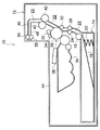
図1及び図2に示すように、画像形成装置10は、筐体となる画像形成装置本体12を備えている。この画像形成装置本体12の下部には、給紙カセット14が配置されている。この給紙カセット14の内部には、フラッパ16が設けられている。このフラッパ16の上部には、所定のサイズの記録紙が積層されている。また、給紙カセット14の近傍には、ピックアップローラ18が配置されている。また、フラッパ16は、積層された記録紙の上面がピックアップローラ18に接するようにバネ部材20により上方に付勢されている。この状態で、ピックアップローラ18が回転駆動すると、摩擦力により記録紙が1枚ずつ記録紙搬送路22に給紙されるようになる。
As shown in FIGS. 1 and 2, the
また、ピックアップローラ18の記録紙送方向下流側には、フィードローラ24とプレスローラ26とが配置されている。このフィードローラ24とプレスローラ26とにより記録紙が記録紙搬送路22を記録紙搬送方向下流側に搬送される。また、フィードローラ24及びプレスローラ26の記録紙搬送方向下流側には、感光体ドラム28と、転写ローラ30と、が配置されている。また、感光体ドラム28の周囲に沿って、紙粉除去ローラ32と、コロナ帯電器34と、がそれぞれ配置されている。また、感光体ドラム28の近傍には、現像器36が配置されている。さらに、現像器36の近傍には、露光ヘッド38が配置されている。
A
上記紙粉除去ローラ32は、導電性のスポンジ等により構成され、転写後の感光体ドラム28の表面に付着したトナーや紙粉を除去する。また、コロナ帯電器34は、コロトロンからの放電により感光体ドラム28の表面を一様に帯電する。コロナ帯電器34により一様に帯電された感光体ドラム28に、露光ヘッド38により画像記録信号に応じて露光することで静電潜像が形成される。そして、現像器36内のトナーを感光体ドラム28に形成された静電潜像に転移させて、静電潜像を可視像化する。また、上述した転写ローラ30は記録紙を挟んで感光体ドラム28と対向する位置に配置されており、転写ローラ30に所定の電圧が印加されると感光体ドラム28の表面に形成されたトナー像が転写ローラ30により記録紙に転写される。
The paper
また、感光体ドラム28及び転写ローラ30の記録紙搬送方向下流側には、定着ローラ40と、定着用プレスローラ42と、が配置されている。記録紙に転写されたトナー像は、記録紙が定着ローラ40及び定着用プレスローラ42により挟持されて加熱・プレスされることにより、定着される。
A
また、定着ローラ40及び定着用プレスローラ42の記録紙搬送方向下流側には、2個の排紙ローラ58及び2個の排紙用プレスローラ(プレスローラ)50がそれぞれ配置されている。詳細には、2個の排紙ローラ58は下方側に位置する下側搬送ガイド48に回転可能となるように配置されており、2個の排紙用プレスローラ50は上方側に位置する上側搬送ガイド(搬送ガイド部材)46に回転可能となるように配置されている。また、各排紙用プレスローラ50は、各排紙ローラ58と対向する位置に設けられている。また、画像形成装置本体12には排紙トレイ44が形成されており、記録紙搬送路22を搬送されてきた記録紙が排紙ローラ58と排紙用プレスローラ50とにより挟支されて排紙トレイ44に排出される。
Further, two
ここで、排紙用プレスローラ50の構成について詳細に説明する。なお、各排紙用プレスローラ50の構成は同一となるため、一方の排紙用プレスローラ50を例にとり以下に説明する。
Here, the configuration of the paper
図2及び図3に示すように、排紙用プレスローラ50は、円筒状のプレスローラ本体部材52を備えている。このプレスローラ本体部材52は、例えば、ポリアセタール(POM)などの樹脂で構成されている。また、プレスローラ本体部材52の両端部には、ゴムで構成されたゴム部材54が装着されている。この各ゴム部材54は、プレスローラ本体部材52の端部に挿入する挿入部54Aと、挿入部54Aに一体成形されプレスローラ本体部材52の径よりも大きな径に設定された拡径部54Bと、で構成されている。さらに、各ゴム部材54の各拡径部54B側から各摺動部材(接触防止部材)56がプレスローラ本体部材52に装着されている。この各摺動部材56は、プレスローラ本体部材52に挿入された各ゴム部材54の各挿入部54Aの径方向内側に挿入される各位置決め部56Aと、各位置決め部56Aと一体成形され各ゴム部材54の各拡径部54Bをプレスローラ本体部材52の各端面にそれぞれ押し付ける押圧部56Bと、で構成されている。この各摺動部材56は、例えばポリアセタール(POM)などの樹脂で構成されている。このように、排紙用プレスローラ50は、プレスローラ本体部材52と、プレスローラ本体部材52を挟むように設けられた一対のゴム部材54と、ゴム部材54を挟むように設けられた一対の各摺動部材56と、を有し、プレスローラ本体部材52とゴム部材54と摺動部材56とは、互いに隣接する部材と嵌合し一体的に回転するように構成されている。
As shown in FIGS. 2 and 3, the paper
また、図2に示すように、上記各排紙用プレスローラ50は、コイルばねで構成された回転軸60が排紙用プレスローラ50を貫通し、上側搬送ガイド46に形成された軸受け部64に回転軸60が回転可能に装着されることにより、上側搬送ガイド46に取り付けられている。
Further, as shown in FIG. 2, each of the paper
また、上側搬送ガイド46には、記録紙の搬送時に回転する複数(本実施形態では3個)のコロ62が取り付けられている。各排紙用プレスローラ50と複数のコロ62は、略一直線上に位置するように配置されている。
A plurality of (three in this embodiment)
さらに、記録紙が排紙ローラ58と排紙用プレスローラ50とにより挟持されて搬送される際に、排紙ローラ58と排紙用プレスローラ50とにより挟持された記録紙の挟持部における記録紙の搬送方向に対して直交する方向の記録紙断面が波型となる。
Further, when the recording paper is nipped and conveyed by the
次に、本実施形態の画像形成装置10の作用について説明する。
Next, the operation of the
図1及び図2に示すように、定着ローラ40及びプレスローラ42によりトナー画像が定着された記録紙は、定着ローラ40及びプレスローラ42の記録紙搬送方向下流側に位置する記録紙搬送路22を搬送されていく。そして、記録紙は、下側搬送ガイド48と上側搬送ガイド46とで構成された記録紙搬送路22を搬送され、やがて排紙ローラ58と排紙用プレスローラ50に到達する。記録紙は、排紙ローラ58と排紙用プレスローラ50とにより挟持されて、排紙ローラ58の回転駆動により排紙トレイ44に排出される。
As shown in FIGS. 1 and 2, the recording paper on which the toner image is fixed by the fixing
ここで、各排紙用プレスローラ50にはゴム部材54が備えられているため、記録紙が排紙ローラ58と排紙用プレスローラ50とにより挟持されるときに、記録紙に所定以上の摩擦力を作用させることができる。これにより、記録紙の排出効果を大幅に向上させることができる。
Here, since each
特に、各排紙用プレスローラ50は、円筒状のプレスローラ本体部材52と、プレスローラ本体部材52の径よりも大きな径のゴム部材54と、を有しているため、記録紙が排紙ローラ58と排紙用プレスローラ50とにより挟持されるときに、ゴム部材54によりニップ圧が増大して所定以上の摩擦力が記録紙に作用させられる。これにより、簡易な構成で、かつ容易に記録紙に所定以上の摩擦力を作用させることができる。
In particular, each
また、各排紙用プレスローラ50の各ゴム部材54と上側搬送ガイド46との間には各摺動部材56が設けられているため、各排紙用プレスローラ50が回転するときに、各ゴム部材54が上側搬送ガイド46に接触することを防止することができる。これにより、各排紙用プレスローラ50が回転するときに、各ゴム部材54が上側搬送ガイド46に擦れて騒音が発生してしまうことを防止できる。
In addition, since each sliding
特に、上側搬送ガイド46がポリカーボネート(PC)、各摺動部材56がポリアセタール(POM)などの樹脂で構成されているため、両者が接触しても大きな騒音が発生することがない。また、上側搬送ガイド46をポリカーボネート(PC)、各摺動部材56をポリアセタール(POM)などの樹脂で構成することにより、成形型により安価かつ容易に成形することができる。
In particular, since the
また、各排紙用プレスローラ50の各ゴム部材54と上側搬送ガイド46の軸受け部64との隙間を埋めるように各摺動部材56の厚みを設定しておくことにより、各排紙用プレスローラ50が軸方向(図2中矢印A方向)に移動することを阻止することができる。この結果、記録紙の排出効果を大幅に向上させることができる。
Further, by setting the thickness of each sliding
また、プレスローラ本体部材52とゴム部材54と摺動部材56とは、互いに隣接する部材と嵌合し一体的に回転するため、各部材間でがたつきが少なくなり、各部材の磨耗を少なくすることができる。また、各部材が一体的に回転するため、搬送時の記録紙をニップする力のばらつきが少なくなり、記録紙の搬送精度を高めることができる。
Further, since the press roller
また、排紙ローラ58と排紙用プレスローラ50とにより挟持された記録紙の挟持部における記録紙の搬送方向に対して直交する方向の記録紙断面が波型であるため、搬送される記録紙に腰を与えることができ、排紙トレイ44に積層される記録紙の折れ曲がりや潜り込みを防止することができる。
Further, since the recording sheet cross section in the direction perpendicular to the recording sheet conveyance direction in the recording sheet nipping portion sandwiched between the
なお、本実施形態の画像形成装置10では、上側搬送ガイド46に配置された各排紙用プレスローラ50に各摺動部材56を取り付けた構成を例にとり説明したが、この構成に限られることなく、画像形成装置10に用いられる全てのローラ部材に適用することができる。
In the
10 画像形成装置
46 上側搬送ガイド(搬送ガイド部材)
50 排紙用プレスローラ(プレスローラ)
52 プレスローラ本体部材
54 ゴム部材
56 摺動部材(接触防止部材)
58 排紙ローラ
10
50 Press roller for paper discharge (press roller)
52 Press
58 Paper discharge roller
Claims (5)
前記プレスローラは、円筒状のプレスローラ本体部材と、前記プレスローラ本体部材の径よりも大きな径であり前記記録紙に所定以上の摩擦力を作用させるゴム部材と、前記ゴム部材と前記搬送ガイド部材との間に設けられ前記ゴム部材が前記搬送ガイド部材に接触することを防止する接触防止部材と、を有し、
前記ゴム部材は、前記プレスローラ本体部材に組み付けたときに前記プレスローラ本体部材の内周側に挿入される挿入部と、前記プレスローラ本体部材の径よりも大きな径である拡径部と、を有し、
前記接触防止部材は、前記プレスローラ本体部材に組み付けたときに前記プレスローラ本体部材の径方向内側に位置する前記挿入部の径方向内側に挿入される位置決め部と、前記プレスローラ本体部材に組み付けたときに前記拡径部を前記プレスローラ本体部材の端面に押し付ける押圧部と、を有することを特徴とする画像形成装置。 Yes and rotatably provided a discharge roller, a press roller which is rotatably arranged at a position facing the conveying guide member and the sheet discharging a position on the rollers constituting the conveyance path of the recording sheet, the And an image forming apparatus that sandwiches the recording paper with the toner image fixed between the paper discharge roller and the press roller and discharges the recording paper to the outside.
The press roller includes a cylindrical press roller main body member, a rubber member having a diameter larger than the diameter of the press roller main body member, and exerts a predetermined frictional force on the recording paper, the rubber member, and the conveyance guide A contact preventing member provided between the member and the rubber member for preventing the rubber member from contacting the transport guide member,
The rubber member is inserted into the inner peripheral side of the press roller body member when assembled to the press roller body member, and an enlarged diameter part having a diameter larger than the diameter of the press roller body member, Have
The contact preventing member is assembled to the press roller body member, and a positioning portion that is inserted radially inside the insertion portion that is located radially inside the press roller body member when assembled to the press roller body member. And a pressing portion that presses the enlarged diameter portion against an end surface of the press roller body member.
前記排紙ローラと前記プレスローラとにより挟持された前記記録紙の挟持部における前記記録紙の搬送方向に対して直交する方向の記録紙断面が波型であることを特徴とする請求項1乃至4のいずれか1項に記載の画像形成装置。 The recording paper is nipped and conveyed by the paper discharge roller and the press roller,
2. The recording paper section in a direction perpendicular to the recording paper conveyance direction in the recording paper clamping portion sandwiched between the paper discharge roller and the press roller is corrugated. 5. The image forming apparatus according to any one of 4 above.
Priority Applications (1)
| Application Number | Priority Date | Filing Date | Title |
|---|---|---|---|
| JP2005013396A JP4210941B2 (en) | 2005-01-20 | 2005-01-20 | Image forming apparatus |
Applications Claiming Priority (1)
| Application Number | Priority Date | Filing Date | Title |
|---|---|---|---|
| JP2005013396A JP4210941B2 (en) | 2005-01-20 | 2005-01-20 | Image forming apparatus |
Publications (2)
| Publication Number | Publication Date |
|---|---|
| JP2006199448A JP2006199448A (en) | 2006-08-03 |
| JP4210941B2 true JP4210941B2 (en) | 2009-01-21 |
Family
ID=36957790
Family Applications (1)
| Application Number | Title | Priority Date | Filing Date |
|---|---|---|---|
| JP2005013396A Expired - Fee Related JP4210941B2 (en) | 2005-01-20 | 2005-01-20 | Image forming apparatus |
Country Status (1)
| Country | Link |
|---|---|
| JP (1) | JP4210941B2 (en) |
Cited By (1)
| Publication number | Priority date | Publication date | Assignee | Title |
|---|---|---|---|---|
| US8741859B2 (en) | 2008-03-28 | 2014-06-03 | Ishihara Sangyo Kaisha, Ltd | Fungicide composition for agriculture and horticulture and method for preventing plant diseases |
Families Citing this family (1)
| Publication number | Priority date | Publication date | Assignee | Title |
|---|---|---|---|---|
| JP5693119B2 (en) * | 2010-09-30 | 2015-04-01 | サトーホールディングス株式会社 | Transfer roller and printer |
-
2005
- 2005-01-20 JP JP2005013396A patent/JP4210941B2/en not_active Expired - Fee Related
Cited By (1)
| Publication number | Priority date | Publication date | Assignee | Title |
|---|---|---|---|---|
| US8741859B2 (en) | 2008-03-28 | 2014-06-03 | Ishihara Sangyo Kaisha, Ltd | Fungicide composition for agriculture and horticulture and method for preventing plant diseases |
Also Published As
| Publication number | Publication date |
|---|---|
| JP2006199448A (en) | 2006-08-03 |
Similar Documents
| Publication | Publication Date | Title |
|---|---|---|
| JP5533336B2 (en) | Fixing apparatus and image forming apparatus | |
| JP4858563B2 (en) | Fixing apparatus and image forming apparatus | |
| JP3758232B2 (en) | Image carrier belt drive mechanism | |
| US9046827B2 (en) | Belt driving apparatus and image forming apparatus | |
| US9891551B2 (en) | Roller member, roller supporting mechanism, and image forming apparatus | |
| US20150277265A1 (en) | Roller member, roller supporting mechanism, and metallic shaft | |
| JP4210941B2 (en) | Image forming apparatus | |
| US9360788B2 (en) | Roller member, roller supporting mechanism, and image forming apparatus | |
| US6024497A (en) | Bushing with molded spring | |
| JP6512138B2 (en) | Fixing device and image forming apparatus | |
| CN108693726A (en) | Image forming apparatus | |
| JP5989244B2 (en) | Sheet conveying apparatus, image reading apparatus, and image forming apparatus | |
| JP6724595B2 (en) | Sheet conveying device and image forming apparatus including the same | |
| US20190129357A1 (en) | Image forming apparatus | |
| JP4097564B2 (en) | Sheet ejector | |
| JP6557068B2 (en) | Sheet conveying apparatus and image forming apparatus | |
| JP7508304B2 (en) | Sheet conveying device and image forming apparatus | |
| US20250244697A1 (en) | Image forming apparatus | |
| JP5195222B2 (en) | Sheet transport device | |
| CN109976124A (en) | image forming apparatus | |
| JP6122797B2 (en) | Fixing apparatus and image forming apparatus | |
| JP4277319B2 (en) | Image forming apparatus | |
| JP4379810B2 (en) | Paper dust removing apparatus and image forming apparatus | |
| JP2010173810A (en) | Recording medium feeding apparatus and image forming apparatus | |
| JP6743757B2 (en) | Fixing device and image forming apparatus |
Legal Events
| Date | Code | Title | Description |
|---|---|---|---|
| A977 | Report on retrieval |
Free format text: JAPANESE INTERMEDIATE CODE: A971007 Effective date: 20080111 |
|
| A131 | Notification of reasons for refusal |
Free format text: JAPANESE INTERMEDIATE CODE: A131 Effective date: 20080221 |
|
| A521 | Request for written amendment filed |
Free format text: JAPANESE INTERMEDIATE CODE: A523 Effective date: 20080408 |
|
| A131 | Notification of reasons for refusal |
Free format text: JAPANESE INTERMEDIATE CODE: A131 Effective date: 20080804 |
|
| A521 | Request for written amendment filed |
Free format text: JAPANESE INTERMEDIATE CODE: A523 Effective date: 20080808 |
|
| TRDD | Decision of grant or rejection written | ||
| A01 | Written decision to grant a patent or to grant a registration (utility model) |
Free format text: JAPANESE INTERMEDIATE CODE: A01 Effective date: 20081002 |
|
| A01 | Written decision to grant a patent or to grant a registration (utility model) |
Free format text: JAPANESE INTERMEDIATE CODE: A01 |
|
| A61 | First payment of annual fees (during grant procedure) |
Free format text: JAPANESE INTERMEDIATE CODE: A61 Effective date: 20081015 |
|
| FPAY | Renewal fee payment (event date is renewal date of database) |
Free format text: PAYMENT UNTIL: 20111107 Year of fee payment: 3 |
|
| R150 | Certificate of patent or registration of utility model |
Ref document number: 4210941 Country of ref document: JP Free format text: JAPANESE INTERMEDIATE CODE: R150 Free format text: JAPANESE INTERMEDIATE CODE: R150 |
|
| FPAY | Renewal fee payment (event date is renewal date of database) |
Free format text: PAYMENT UNTIL: 20121107 Year of fee payment: 4 |
|
| R250 | Receipt of annual fees |
Free format text: JAPANESE INTERMEDIATE CODE: R250 |
|
| FPAY | Renewal fee payment (event date is renewal date of database) |
Free format text: PAYMENT UNTIL: 20131107 Year of fee payment: 5 |
|
| R250 | Receipt of annual fees |
Free format text: JAPANESE INTERMEDIATE CODE: R250 |
|
| FPAY | Renewal fee payment (event date is renewal date of database) |
Free format text: PAYMENT UNTIL: 20131107 Year of fee payment: 5 |
|
| R250 | Receipt of annual fees |
Free format text: JAPANESE INTERMEDIATE CODE: R250 |
|
| R250 | Receipt of annual fees |
Free format text: JAPANESE INTERMEDIATE CODE: R250 |
|
| R250 | Receipt of annual fees |
Free format text: JAPANESE INTERMEDIATE CODE: R250 |
|
| R250 | Receipt of annual fees |
Free format text: JAPANESE INTERMEDIATE CODE: R250 |
|
| R250 | Receipt of annual fees |
Free format text: JAPANESE INTERMEDIATE CODE: R250 |
|
| R250 | Receipt of annual fees |
Free format text: JAPANESE INTERMEDIATE CODE: R250 |
|
| R250 | Receipt of annual fees |
Free format text: JAPANESE INTERMEDIATE CODE: R250 |
|
| R250 | Receipt of annual fees |
Free format text: JAPANESE INTERMEDIATE CODE: R250 |
|
| R250 | Receipt of annual fees |
Free format text: JAPANESE INTERMEDIATE CODE: R250 |
|
| R250 | Receipt of annual fees |
Free format text: JAPANESE INTERMEDIATE CODE: R250 |
|
| LAPS | Cancellation because of no payment of annual fees |