JP4211908B2 - Board crusher - Google Patents
Board crusher Download PDFInfo
- Publication number
- JP4211908B2 JP4211908B2 JP35666099A JP35666099A JP4211908B2 JP 4211908 B2 JP4211908 B2 JP 4211908B2 JP 35666099 A JP35666099 A JP 35666099A JP 35666099 A JP35666099 A JP 35666099A JP 4211908 B2 JP4211908 B2 JP 4211908B2
- Authority
- JP
- Japan
- Prior art keywords
- plate
- crushing
- arc
- core material
- container
- Prior art date
- Legal status (The legal status is an assumption and is not a legal conclusion. Google has not performed a legal analysis and makes no representation as to the accuracy of the status listed.)
- Expired - Fee Related
Links
Images



Landscapes
- Disintegrating Or Milling (AREA)
Description
【0001】
【産業上の利用分野】
この発明は、ボードの粉砕処理装置に関するものである。
【0002】
【従来の技術】
例えば、ビルの建築現場では大量の石膏ボードが使用されるが、これらを建て込んでゆく過程で寸法切りと呼ばれる作業、すなわち規格サイズで搬入された石膏ボードを所望とする寸法に切り出す作業がなされる。したがって、切り出された残りの部分は、不要な部分となって現場に残る。従来、建築現場ではこのような余剰ボードが大量に残され、その処理に困っていた。余剰ボードは建築現場に限らず、石膏ボードの製造現場においても同様に生じる。すなわち、製造現場においては成形直後のボードサイズは出荷時の寸法よりも大きく設定してあり、成形固化後に規格サイズに切り出しており、この切り出し時に余剰ボードが生じる。
【0003】
よく知られるように、石膏ボードは石膏を芯材としてその表裏にボード用原紙を貼り合わせた構成である。したがって、石膏分を紙分と分離して高純度で取り出すことができれば、少なくとも石膏分については再利用が期待できる。
また、石膏ボードを産業廃棄物として処理する場合には、その廃棄場所として安定型処分場、管理型処分場、特別管理型処分場の3つがある。安定型処分場は、地面に掘った穴に廃棄物を直接投入するようにしたものであり、管理型処分場は、地面に掘った穴にビニルシートを敷いてそこに廃棄物を投入するようにしたものであり、これらの処分場に投棄できるのは、石膏等の無機成分物質のみに限られ、紙等の有機成分物質を廃棄することはできないが、設備コストを抑えることができるという利点がある。一方、特別管理型処分場は、地面に掘った穴にコンクリート壁を作ってその中に廃棄物を投入するようにしたものであり、ここには無機成分物質に限らず有機成分物質も廃棄することができるのであるが、その反面設備コストが高くつく。したがって、石膏ボードを廃棄する場合には、無機成分(石膏)と有機成分(紙)とを高純度で分離し、石膏成分のみを安定型処分場に廃棄し、紙は消却処分することが望ましい。
【0004】
そこで、石膏ボードを石膏成分と紙に分離する手段として、従来は、ボールミルを用いることが考えられていた。ボールミルは、回転容器内に粉砕手段であるボールを収容したものであり、この中に荒く砕いた石膏ボードを投入し、回転容器を回転させてボールを石膏ボートに衝突させることで、その石膏ボードを徐々に細かく砕いて微粒化させるとともに、粉砕の過程で石膏と紙とを分離するようにしたものである。
【0005】
【発明が解決しようとする課題】
上記ボールミルによる粉砕方法では、回転容器内でボールが転がる際に金属同士の衝撃による騒音が発せられるだけでなく、ボールが石膏ボードに衝突することによっても騒音が発生するという問題がある。
本願発明は上記事情に鑑みて創案され、騒音の発生を抑えることのできるボードの粉砕処理装置を提供することを目的としている。
【0006】
【課題を解決するための手段】
請求項1の発明は、芯材の表面にシート層を積層してなるボード片を、前記芯材分とシート分とに分別するための装置であって、断面が円弧状をなす円弧状壁部及びこの円弧状壁部の斜め上向きの両端縁から更に接線状に斜め外上方へ延出した一対のテーパ状壁部を備えた粉砕容器と、軸線を前記円弧状壁部の円弧の中心と平行に向けた回転軸、この回転軸の外周に取り付けた螺旋板及びこの螺旋板の軸線方向に対向する板面同士を連結するように取り付けた攪拌板を備えて前記円弧状壁部の内周面に沿って回転可能な回転粉砕部材とを備え、前記螺旋板における前記円弧状壁部と対応する外周縁には鋸歯状の凹凸が形成されていると共に、前記円弧状壁部には前記粉砕容器外へ開口する排出口が形成され、前記粉砕容器の前記円弧状壁部と前記螺旋板との間には、前記ボード片を擂り潰し可能な隙間が設けられ、かつ、前記粉砕容器の前記テーパ状壁部と前記螺旋板との間には、上方ほど広くなる隙間が設けられている構成とした。
【0008】
請求項2の発明は、請求項1の発明において、前記撹拌板には逃がし孔が形成されている構成とした。
請求項3の発明は、請求項1又は請求項2のいずれかの発明において、前記円弧状壁部には、前記回転粉砕部材による送り方向に沿った所定領域に亘って複数の芯材分排出口が形成されているとともに、この芯材分排出口よりも送り方向先方に位置し且つその芯材分排出口よりも大きく開口されたシート分排出口が形成されている構成とした。
【0010】
【発明の作用及び効果】
[請求項1の発明]
粉砕容器内に投入したボード片は、円弧状壁部と回転粉砕部材との隙間に噛み込んで擂り潰されつつ芯材分とシート分とに分離される。ボード片を打圧粉砕するのではなく擦り潰すようにしたので騒音が発生する虞がない。
擦り潰しにより粉砕・分離された芯材分とシート分は、排出口を通って粉砕容器外へ排出されるので、粉砕の運転を止めなくても、芯材分とシート分を回収することが可能である。
【0011】
ボード片は、螺旋板と弧状面との間で粉砕されつつ螺旋板の板面で押されて回転軸の軸線方向へ送られるので、ボード片、芯材分及びシート分が粉砕容器の一カ所に溜まることがなく、粉砕処理の効率が向上する。
螺旋板に鋸歯状の凹凸を設けたので、ボード片の粉砕効率が向上する。
ボード片、芯材分及びシート分は、螺旋板によって軸線方向に送られるだけでなく撹拌板によって周方向にも押されるので、弧状面上を広範囲に亘って分散され、粉砕効率が更に向上する。
【0012】
[請求項2の発明]
攪拌板に逃がし孔を形成したので、ボード片、芯材分及びシート分の量が多い場合でも、攪拌抵抗を低減することができる。
[請求項3の発明]
ボード材を粉砕しつつ送る過程では、芯材分は擂り潰しによって細かく砕かれるのに対し、シート分は擂り潰されても比較的大きなシート片の形態を維持する。よって、螺旋板によって送られる過程では、まず、芯材分だけが芯材分排出口から排出され、その後、シート分がシート分排出口から排出される。このように、芯材分だけを分別回収することができる。
【0014】
【発明の実施の形態】
[実施形態1]
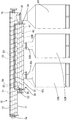
以下、本発明を具体化した実施形態1を図1乃至図5を参照して説明する。
本実施形態のボード粉砕処理装置は、粉砕容器10、回転粉砕部材20、回収容器30、回転回収部材40、及び回収タンクを備えて構成される。尚、以下の説明において、左右の方向は図1、図4及び図5を基準とする。
[粉砕容器10]
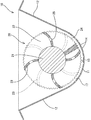
粉砕容器10は、ほぼ120°の角度範囲に亘る下膨らみの円弧状壁部11と、この円弧状壁部11の斜め上向きの両端縁から更に接線状に斜め外上方へ延出した一対のテーパ状壁部12とからなり、円弧状壁部11の円弧の中心軸に沿って一定の断面形状で所定の範囲に亘る長さを有し、全長に亘って上方へ開放されている。この粉砕容器10の円弧状壁部11の内周面は、後述する回転粉砕部材20と協動して石膏ボード(本発明の構成要件であるボード片)を粉砕する弧状面13となっている。円弧状壁部11のうち、正面から視て左右方向中央よりも少し左寄りの位置から右端部の近い位置に至る広い範囲には、小径の芯材分排出口14が多数個整列して形成されており(図4を参照)、これらの芯材分排出口14は、弧状面13から粉砕容器10の外面(下面)へと連通している。かかる芯材分排出口14の口径は、後述する螺旋板22と弧状面13との間の隙間17の寸法と同じかそれよりも小さい寸法とされている。また、これら芯材分排出口14よりも右側の位置(粉砕容器10の右端位置)には、シート分排出口15が弧状面13かから粉砕容器10の外面(下面)側への連通されている。このシート分排出口15の位置は、回転粉砕部材20の螺旋板22による送り方向において芯材分排出口14よりも先方に位置していることになる。また、このシート分排出口15の口径は、芯材分排出口14の口径に比べて相当に大きい寸法に設定されている。かかるシート分排出口15にはシート分回収タンク51が取り付けられている。
【0015】
[回転粉砕部材20]
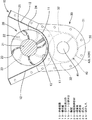
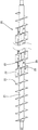
回転粉砕部材20は、軸線を弧状面13の円弧の中心と平行に向けた回転軸21と、この回転軸21の外周に取り付けた螺旋板22と、この螺旋板22の軸線方向に対向する板面同士を連結するように取り付けた攪拌板23とからなり、全体としてスクリュー状をなしている。回転軸21は、粉砕容器10の両端の軸受16に回転可能に支持され、図示しないモータにより回転駆動されるようになっている。また、螺旋板22は、1枚板を螺旋状に曲げ加工して回転軸21に一定ピッチで取り付けたものであり、その外周縁には鋸歯状をなす細かい凹凸24が全長に亘って形成されている(図2及び図3を参照)。かかる螺旋板22の外周縁と弧状面13とは同心状に配されているとともに、双方の間には所定の寸法の隙間17が確保されている。この螺旋板22と弧状面13との間の隙間17の寸法は、石膏ボードが噛み込み可能であり、且つその噛み込んだ石膏ボードが擂り潰されるような寸法に設定されている。また、攪拌板23は、軸線方向に視ると弧状をなしており、4枚1組で螺旋板22の間に取り付けられている。各々の組においては4枚の攪拌板23が90°間隔で配されているが、隣接する2つの組同士の間では、一方の組の攪拌板23に対して他方の組の攪拌板23が45°位相がずれた位置関係となっている(図2及び図3を参照)。また、各攪拌板23には、その表裏両面間に貫通する(周方向に貫通する)逃がし孔25が形成されている。
【0016】
[回収容器30]
回収容器30は、ほぼ180度の角度範囲に亘る下膨らみの円弧状壁部31と、この半円弧状壁部31の両端から上方へ延出する一対の側壁32とからなり、円弧状壁部31の弧の中心を粉砕容器10の弧の中心と平行に向けた状態で、粉砕容器10の下面に取り付けられている。回収容器30は、粉砕容器10における全ての芯材分排出口14と対応し、且つシート分排出口15からは外れるように取り付けられている。取り付けられた回収容器30の内部は、その上面の開口を粉砕容器10の円弧状壁部31で塞がれてほぼ密閉された状態となっている。また、円弧状壁部31には、左右2つの芯材分回収口33L,33Rが大きく開口されており、各芯材分回収口33L,33Rには、夫々、芯材分回収タンク52L,52Rが取り付けられている。
【0017】
[回転回収部材40]
回収容器30の内部には、回転回収部材40が収容されている。回転回収部材40は、軸線を弧状面13の円弧の中心と平行に向けた回転軸41と、この回転軸41の外周に取り付けた螺旋板42L,42Rとからなり、全体としてスクリュー状をなしている。回転軸41は、回収容器30の両端の軸受34に回転可能に支持され、図示しないモータにより回転駆動されるようになっている。また、螺旋板42L,42Rは左右2つに分かれており、左側の螺旋板42Lは、回転軸41の左端部、即ち左側の芯材分回収口33Lよりもさらに左側の短い領域に亘って配され、右側の螺旋板42Rは、左側の芯材分回収口33Lよりも右側であって右側の芯材分回収口33Rを含む長い領域に亘って配されている。かかる左右両側の螺旋板42L,42Rの螺旋の向きは、互いに逆ねじれとなっている。また、この両螺旋板42L,42Rの外周縁と円弧状壁部31の内周との隙間35は、粉砕容器10における螺旋板の外周と弧状面13との隙間よりも小さい寸法とされている。
【0018】
[実施形態1の作用]
石膏ボード(図示せず)を粉砕する際には、粉砕容器10内の回転粉砕部材20をその螺旋板22による送り方向が右向きとなる方向へ回転駆動するとともに、回収容器30内の回転回収部材40をその右側の螺旋板42Rによる送り方向が左向きとなるように回転駆動する。この状態で、荒く砕いた石膏ボードを粉砕容器10の左端部から投入する。すると、投入された石膏ボードは、回転粉砕部材20の螺旋板22によって粉砕容器10内を右方へ送られながら、螺旋板22の外周と弧状面13との隙間17に噛み込み、その螺旋板22と弧状面13との間で擂り潰される。これにより、石膏ボードが石膏分(本発明の構成要件である芯材分)と紙分(本発明の構成要件であるシート分)とに分離されるとともに、石膏分が細かく砕かれて次第に微粒化していく。尚、石膏分から分離した紙分は、螺旋板22と弧状面13との間に噛み込んでも柔軟に変形するため、比較的大きな(芯材分排出口14の口径よりも大きな)紙片の状態が保たれる。
【0019】
そして、分離・粉砕されつつ送られる石膏分と紙分のうち、初期のうちに微粒化された石膏分は、送り方向における基端側(左側)に位置する芯材分排出口14から回収容器30内に落下する。芯材分排出口14の口径よりも大きい石膏分は更に擂り潰されて微粒化された後、送り方向先方側(右側)に位置する芯材分排出口14から回収容器30内に落下する。尚、紙分は、上記したように大きな紙片の状態を維持するため、芯材分排出口14から回収容器30へ排出されることはない。
【0020】
このようにして、芯材分排出口14の開口領域内を送られる間に、大部分の石膏分は微粒化されて回収容器30内に回収され、残りの僅かな石膏分と全ての紙分が粉砕容器10の右端部(送り方向終端部)に至り、シート分排出口15からシート分回収タンク51内に落下して回収される。
さて、回収容器30内に落下した石膏分のうち、左側の芯材分回収口33Lよりも左側に落下した石膏分は、左側の螺旋板42Lによって右側へ送られて左側の芯材分回収口33Lから芯材分回収タンク52L内に回収される。一方、左側の芯材分回収口33Lよりも右側に落下した石膏分は、右側の螺旋板42Rによって左側へ送られ、その一部は送りの途中で右側の芯材分回収口33Rから芯材分回収タンク52Rに回収され、それ以外は左側の芯材分回収口33Lから別の芯材分回収タンク52L内に回収される。
【0021】
[実施形態1の効果]
▲1▼石膏ボードを粉砕する手段として、石膏ボードを弧状面13と回転粉砕部材20との隙間に噛み込ませて擂り潰すことにより、石膏分と紙分とに分離するとともに、石膏分を徐々に砕いて微粒化するようにしたので、ボールミルのように石膏ボードを打圧して粉砕する装置とは異なり、騒音が発生する虞がない。
▲2▼弧状面13には粉砕容器10外へ開口する芯材分排出口14とシート分排出口15を形成して、粉砕・分離した石膏分と紙分を各排出口14,15を通して粉砕容器10外へ排出させ、さらに、芯材分排出口14から排出された石膏分を受ける回収容器30に芯材分回収タンク52L,52Rに連なる芯材分回収口33L,33Rを形成したので、粉砕の運転を止めなくても、石膏分と紙分を回収することが可能である。
【0022】
▲3▼石膏ボードを、回転粉砕部材20と弧状面13との隙間17で粉砕しつつ螺旋板22の板面で押して回転軸21の軸線方向へ送るようにしたので、石膏ボード、石膏分及び紙分が粉砕容器10の一カ所に溜まることがなく、粉砕処理の効率が向上する。
▲4▼螺旋板22における弧状面13と対応する外周縁には、鋸歯状の凹凸24を形成したので、石膏ボードの粉砕効率に優れる。
▲5▼螺旋板22の軸線方向に対向する板面間に径方向の撹拌板23を設け、石膏ボード、石膏分及び紙分を、螺旋板22によって軸線方向に送るだけでなく撹拌板23によって周方向にも押して攪拌するようにしたので、石膏ボード等が弧状面13上を広範囲に亘って周方向へ分散され、粉砕効率が更に向上する。
【0023】
▲6▼攪拌板23に逃がし孔25を形成し、石膏ボード、石膏分及び紙分がこの逃がし孔25を通り抜けることができるようにしたので、石膏ボード等の投入量が多い場合でも、攪拌抵抗を低減し、回転粉砕部材20の駆動源への負担を軽減することができる。
▲7▼石膏ボードを粉砕しつつ送る過程では、石膏分は擂り潰しによって細かく砕かれるのに対し、紙分は擂り潰されても比較的大きなシート片の形態を維持することに着目し、弧状面13には、送り方向に沿った所定領域に亘って複数の芯材分排出口14を形成するとともに、この芯材分排出口14よりも送り方向先方にその芯材分排出口14よりも大きく開するシート分排出口15を形成した。これにより、送る過程では、まず、石膏分だけが芯材分排出口14から排出され、その後、紙分がシート分排出口15から排出されるようになるので、石膏分だけを紙分とは分別して回収することが可能となっている。
【0024】
[参考例]
次に、本発明に関連する参考例を図6及び図7を参照して説明する。
本実施形態2のボード粉砕処理装置は、粉砕容器60、回収容器70、回転粉砕部材80、及び駆動機構90を備えて構成されている。
[粉砕容器60]
粉砕容器60は、全体として軸線を上下方向に向けた円錐状をなし、上端から下端に向けて径寸法が小さくなっている。粉砕容器60の内周面は、その全体に亘り、石膏ボード(図示せず)を粉砕するための弧状面61となっている。粉砕容器60の上端面には支持壁62が設けられ、この支持壁62の外周縁部には、上方へ筒状に立ち上がる投入口63が粉砕容器60内に連通する形態で形成されている。また、支持壁62には、粉砕容器60の円錐の軸線と同心の上部軸受64が固定されており、この上部軸受64には、回転粉砕部材80の回転軸81の上端部が貫通状態に支持される。
【0025】
[回収容器70]
粉砕容器60の下方には、その最も径の小さい下端部に連なるように回収容器70が設けられている。回収容器70には、粉砕されて微粒化状となった石膏分(図示せず)と石膏分から分離した紙分(図示せず)とが収容され、図示しない底部から石膏分と紙分が回収容器70外へ取り出されるようになっている。また、回収容器70の上端部(粉砕容器60の下端部に近い位置)には、その内周における周方向に間隔を空けた複数箇所から中央へ延出するアーム71が設けられ、これら複数本のアーム71の延出端には下部軸受72に連結されており、これらのアーム71によって下部軸受72が回収容器70の中空に支持されている。この下部軸受72は、粉砕容器60の上部軸受64と同様、粉砕容器60の円錐の軸線と同心とされ、この下部軸受72には回転軸81の下端部が貫通状態で支持される。
【0026】
[回転粉砕部材80]
回転粉砕部材80は、回転軸81、受け板82及び粉砕板83から構成される。回転軸81は、その軸線を粉砕容器60の円錐の軸線と同軸の上下方向に向けたものであり、回転軸81の上端部と下端部は、夫々、上部軸受64と下部軸受72とに貫通され、軸線周りの回転及び軸線に沿った上下方向の変位を可能に支持されている。尚、この回転軸81における上部軸受64よりも上方の端部は後述するギヤボックス94に支持されている。回転軸81の外周には、径方向へ螺旋状に張り出す1枚の受け板82が固着されている。この受け板82の外周縁82Aは、粉砕容器60の弧状面61と対応するように上方から下方に向かって次第に外径が小さくなっている。また、受け板82の外周縁82Aと弧状面61との隙間Sは、上端から下端に至る全領域に亘って均一な寸法となっている。粉砕板83は、平板状をなし、受け板82における上下に対向する面同士の間に上下に差し渡されるように取り付けられている。粉砕板83は、受け板82の螺旋経路の全体に亘って90°間隔で複数毎設けられている。粉砕板83の内縁は回転軸81に連なり、粉砕板83の外縁83Aは、弧状面61に対し上下方向において均一の隙間Sが空くように寸法設定されている。この粉砕板83と弧状面61との隙間は、受け板82と弧状面61との隙間Sと同じ寸法とされている。
【0027】
[駆動機構90]
支持壁62の上面にはハウジング91が取り付けられ、このハウジング91の上面には、エアシリンダ92が、そのロッド93をハウジング91内に下向きに突出させた状態で固定されており、エアシリンダ92の作動によりロッド93が上下方向へ進退移動する。ロッド93の下端にはギヤボックス94が一体移動可能に固定され、ギヤボックス94の外側面にはモータ95が固定されているとともに、ギヤボックス94内には、回転軸81の上端部が挿入されている。モータ95は正逆両方向に回転可能であり、その回転駆動力は、ギヤボックス94内のギヤ(図示せず)を介すことにより、減速されて回転軸81に伝達される。尚、回転軸81の上端部は、ギヤボックス94に対して一体的に上下動し得るように、且つ相対回転を許容された状態に支持されている。
【0028】
[参考例の作用]
石膏ボード(図示せず)を粉砕する際には、モータ95を駆動し、粉砕容器60内の回転粉砕部材80を回転させる。この回転方向は正逆いずれの方向でもよい。この状態で、粗く砕いた石膏ボードを投入口63から粉砕容器60内に投入する。すると、投入された石膏ボードは、最も上端のほぼ一周分の受け板82上に載置されるとともにその受け板82の傾斜に沿って滑り、粉砕板83によって堰き止められた状態で貯留される。即ち、石膏ボードは、受け板82と粉砕板83とによって区画された複数の貯留空間84内に分けて貯留される。
【0029】
貯留された石膏ボードは、回転粉砕部材80の回転運動に伴い、粉砕板83の外縁83Aと弧状面61との間の隙間Sに噛み込み、擂り潰される。これにより、石膏ボードが石膏分(本発明の構成要件である芯材分)と紙分(本発明の構成要件であるシート分)とに分離されるとともに、石膏分が細かく砕かれて微粒化される。尚、石膏分から分離した紙分は、粉砕板83と弧状面61との間に噛み込んでも柔軟に変形するため、比較的大きな紙片の状態が保たれる。
【0030】
そして、分離・粉砕された石膏分と紙分の大部分は、受け板82の外周縁82Aと弧状面61との隙間Sを通り、弧状面61に沿いつつ下側の受け板82の外周縁82Aとの隙間Sを通り抜けつつ滑り落ち、一気に回収容器70内に収容される。また、受け板82と弧状面61との隙間Sを通り抜けた石膏分と紙分の一部は、その下方に位置する貯留空間84内に落下してその受け板82上に載置され、再び粉砕板83と弧状面61との間に噛み込んで更に細かく擂り潰され、その後、受け板82と弧状面61との隙間Sを通って回収容器70に収容される。また、分離・粉砕された石膏分及び紙分のうち、粉砕板83の外縁83Aにおける比較的上方位置で擂り潰されたものは、受け板82と弧状面61との隙間Sを通らずに、その粉砕板83よりも螺旋方向下方に隣接する貯留空間84へと移動し、ここに貯留された状態で再び擂り潰されることになる。尚、擂り潰しが進むと、最上位置の貯留空間84内の石膏ボードが少なくなるので、その量に応じて石膏ボードを追加投入する。このようにして、全ての石膏ボードが粉砕され、回収容器70に収容される。
【0031】
さて、参考例では、粉砕板83と弧状面61との隙間Sを任意に調節することができるようになっている。即ち、隙間Sを大きくする場合には、エアシリンダ92を作動してロッド93を上方へ引き込むように収縮させ、ギヤボックス94、モータ95及び回転粉砕部材80をロッド93と一体に上方へ変位させる。弧状面61は上方に向かって拡径しているので、回転粉砕部材80が上昇すると、粉砕板83と弧状面61との隙間Sが拡大する。また、粉砕板83と弧状面61との隙間Sを小さくする場合には、上記とは逆に、ロッド93を下方へ進出するようにエアシリンダ92を駆動すればよい。尚、粉砕板83と弧状面61との隙間Sを大きく又は小さくすると、受け板82と弧状面61との隙間Sも大きく又は小さくなる。
【0032】
[参考例の効果]
上記参考例においては、弧状面61を円錐状とするとともに、回転粉砕部材80(受け板82及び粉砕板83)の外周82A,83Aを円錐状の弧状面61に沿った形状とし、回転粉砕部材80を円錐の軸線と平行な方向へ変位させるようにしたので、回転粉砕部材80と弧状面61との間の隙間Sの寸法を任意に変更することができる。これにより、粉砕粒のサイズを任意に設定することができる。
【0033】
また、回転粉砕部材の外周全体を円錐面にした場合には、粉砕容器60内に投入可能なボード片の量やサイズに制約がある。しかし、本実施形態2では、回転粉砕部材80が、円錐の軸線に沿った回転軸81と、この回転軸81の外周から径方向に張り出す受け板82と、この受け板82の上面から立ち上がる粉砕板83とを備え、粉砕板83の外縁83Aと弧状面61との間に、石膏ボードを擦り潰し可能な隙間Sを設けた形態としたので、受け板82の上方に石膏ボードを貯留できる貯留空間84が確保されている。このように貯留空間84を確保したことにより、サイズの大きい石膏ボードを多量に投入することができ、少量ずつ小分けにして投入する場合に比べて作業性が良い。また、石膏ボードのサイズについても比較的大きいまま粉砕容器60に投入することができるので、粉砕の準備工程が簡単で済む。
【0034】
[他の実施形態]
本発明は上記記述及び図面によって説明した実施形態に限定されるものではなく、例えば次のような実施態様も本発明の技術的範囲に含まれ、さらに、下記以外にも要旨を逸脱しない範囲内で種々変更して実施することができる。
(1)上記実施形態1では粉砕容器に排出口を形成して粉砕中に芯材分とシート分を回収できるようにしたが、本発明によれば、排出口を設けずに、粉砕運転を停止した状態で芯材分とシート分を回収するようにしてもよい。
【0035】
(2)上記実施形態1において撹拌板に逃がし孔を形成しない構造とすることもできる。
【0036】
(3)上記実施形態1において、螺旋板に撹拌板と同様に逃がし孔を形成してもよい。
【図面の簡単な説明】
【図1】実施形態1の正面図
【図2】側面図
【図3】粉砕容器及び回転粉砕部材の拡大側面図
【図4】粉砕容器の平面図
【図5】回転粉砕部材の一部切欠正面図
【図6】 参考例において弧状面と回転粉砕部材との隙間を大きくした状態を示す断面図
【図7】弧状面と回転粉砕部材との隙間を小さくした状態を示す断面図
【符号の説明】
10…粉砕容器
13…弧状面
14…芯材分排出口
15…シート分排出口
17…隙間
20…回転粉砕部材
21…回転軸
22…螺旋板
23…攪拌板
24…凹凸
25…逃がし孔
60…粉砕容器
61…弧状面
80…回転粉砕部材
81…回転軸
82…受け板
83…粉砕板
S…隙間[0001]
[Industrial application fields]
The present invention relates to a board crushing apparatus.
[0002]
[Prior art]
For example, a large amount of gypsum board is used at a building construction site, and in the process of building these, a work called dimension cutting, that is, a work of cutting a gypsum board carried in a standard size to a desired size is performed. The Therefore, the remaining part cut out remains as an unnecessary part on the site. Conventionally, a large amount of such surplus boards have been left at construction sites, and it has been difficult to process them. The surplus board is generated not only at the construction site but also at the gypsum board manufacturing site. That is, at the manufacturing site, the board size immediately after molding is set to be larger than the dimension at the time of shipment, and the board is cut out to a standard size after forming and solidifying.
[0003]
As is well known, gypsum board has a structure in which gypsum is used as a core material and base paper for board is bonded to both sides. Accordingly, if the gypsum content can be separated from the paper content and taken out with high purity, at least the gypsum content can be expected to be reused.
Further, when gypsum board is treated as industrial waste, there are three disposal sites: a stable disposal site, a management disposal site, and a special management disposal site. In the stable disposal site, waste is put directly into the hole dug in the ground, and in the managed disposal site, vinyl sheet is placed in the hole dug in the ground and waste is put there. The only thing that can be dumped at these disposal sites is only inorganic component materials such as gypsum, and organic component materials such as paper cannot be discarded, but the advantage that equipment costs can be reduced. There is. On the other hand, a specially managed disposal site is a concrete wall made in a hole dug in the ground, and waste is put into it. Here, not only inorganic components but also organic components are discarded. However, the equipment cost is high. Therefore, when discarding gypsum board, it is desirable to separate inorganic components (gypsum) and organic components (paper) with high purity, dispose of gypsum components only in a stable disposal site, and dispose of paper. .
[0004]
Thus, conventionally, it has been considered to use a ball mill as a means for separating the gypsum board into a gypsum component and paper. A ball mill contains balls that are pulverizing means in a rotating container, and a rough crushed gypsum board is put into this, and the rotating container is rotated so that the balls collide with a gypsum boat. Is gradually pulverized into fine particles and gypsum and paper are separated in the process of pulverization.
[0005]
[Problems to be solved by the invention]
The ball milling method described above has a problem that not only noise due to impact between metals is generated when the ball rolls in the rotating container, but also noise is generated when the ball collides with the gypsum board.
The present invention has been made in view of the above circumstances, and an object thereof is to provide a board crushing apparatus capable of suppressing the generation of noise.
[0006]
[Means for Solving the Problems]
The invention of claim 1 is an apparatus for separating a board piece formed by laminating a sheet layer on the surface of a core material into the core material part and the sheet part,A pair of tapered wall portions that extend further obliquely outward and upward in a tangential manner from both ends of the arc-shaped wall portion having an arc-shaped cross section and obliquely upward ends of the arc-shaped wall portion.A crushing container comprising:A rotating shaft whose axis is directed parallel to the center of the arc of the arc-shaped wall, a spiral plate attached to the outer periphery of the rotating shaft, and a stirring plate attached so as to connect plate surfaces facing each other in the axial direction of the spiral plate A plate is provided along the inner peripheral surface of the arcuate wall portionA rotatable crushing member,The outer peripheral edge of the spiral plate corresponding to the arcuate wall is formed with serrated irregularities, and the arcuate wall is formed with a discharge port that opens to the outside of the crushing vessel. Between the arcuate wall portion and the spiral plate is provided a gap capable of crushing the board piece, and between the tapered wall portion of the grinding container and the spiral plate, There is a gap that becomes wider toward the topThe configuration.
[0008]
Claim2The invention of claim1In the invention, the stirring plate has a relief hole.
Claim3The invention ofClaim 1 or claim 2In any one of the inventions,Arc wallAre formed with a plurality of core material discharge ports over a predetermined region along the feed direction by the rotary pulverizing member, and are located further forward in the feed direction than the core material discharge ports and the core material The sheet outlet is formed so as to be larger than the part outlet.
[0010]
[Action and effect of the invention]
[Invention of Claim 1]
The board pieces thrown into the crushing containerArc wallThe core material and the sheet are separated while being crushed by being bitten into the gap between the rotary crushing member and the rotary crushing member. Since the board pieces are crushed rather than crushed by pressure, there is no risk of noise.
Since the core material and the sheet material crushed and separated by crushing are discharged out of the pulverization container through the discharge port, the core material and the sheet content can be recovered without stopping the pulverization operation. Is possible.
[0011]
Since the board piece is pushed between the spiral plate and the arcuate surface while being pressed by the plate surface of the spiral plate and fed in the axial direction of the rotation shaft, the board piece, the core material and the sheet part are provided in one place in the grinding container. The efficiency of pulverization is improved.
Since the spiral plate is provided with serrated irregularities, the efficiency of crushing the board pieces is improved.
Since the board piece, the core material and the sheet are not only sent in the axial direction by the spiral plate but also pushed in the circumferential direction by the stirring plate, they are dispersed over a wide range on the arcuate surface, and the grinding efficiency is further improved. .
[0012]
[Claims2Invention of]
Since the escape hole is formed in the stirring plate, the stirring resistance can be reduced even when the amount of the board piece, the core material and the sheet is large.
[Claims3Invention of]
In the process of feeding while pulverizing the board material, the core material is finely crushed by crushing, while the sheet is maintained in the form of a relatively large sheet piece even when crushed. Therefore, in the process of being sent by the spiral plate, first, only the core material is discharged from the core material discharge port, and then the sheet is discharged from the sheet discharge port. In this way, only the core material can be collected separately.
[0014]
DETAILED DESCRIPTION OF THE INVENTION
[Embodiment 1]
A first embodiment embodying the present invention will be described below with reference to FIGS.
The board crushing processing apparatus of the present embodiment includes a crushing
[Crushing container 10]
The crushing
[0015]
[Rotating and grinding member 20]
The
[0016]
[Recovery container 30]
The
[0017]
[Rotary recovery member 40]
A
[0018]
[Operation of Embodiment 1]
When crushing a gypsum board (not shown), the
[0019]
Of the gypsum and paper sent while being separated and pulverized, the gypsum that has been atomized in the initial stage is collected from the
[0020]
In this way, most of the gypsum content is atomized and collected in the
Of the gypsum that has fallen into the
[0021]
[Effect of Embodiment 1]
(1) As a means of pulverizing the gypsum board, the gypsum board is bitten into the gap between the
(2) The arc-shaped
[0022]
(3) Since the gypsum board is pushed by the plate surface of the
(4) Since the
(5) A
[0023]
(6) The
(7) In the process of crushing and sending the gypsum board, the gypsum content is finely crushed by crushing, while the paper content is maintained in a relatively large sheet shape even when crushed. A plurality of core
[0024]
[Reference example]
Next, the present inventionReference examples related toWill be described with reference to FIGS.
The board crushing processing apparatus according to the second embodiment includes a crushing
[Crushing container 60]
The crushing
[0025]
[Recovery container 70]
A
[0026]
[Rotating and grinding member 80]
The
[0027]
[Drive mechanism 90]
A
[0028]
[Reference exampleAction]
When crushing a gypsum board (not shown), the
[0029]
The stored gypsum board is bitten into the gap S between the
[0030]
Then, most of the separated and crushed gypsum and paper passes through the gap S between the outer
[0031]
Now,Reference exampleThe gap S between the pulverizing
[0032]
[Reference exampleEffect]
the aboveReference example, The arc-shaped
[0033]
Further, when the entire outer periphery of the rotary pulverizing member is conical, there are restrictions on the amount and size of board pieces that can be put into the pulverizing
[0034]
[Other Embodiments]
The present invention is not limited to the embodiment described with reference to the above description and drawings. For example, the following embodiments are also included in the technical scope of the present invention, and further, within the scope not departing from the gist of the invention other than the following. Various modifications can be made.
(1) In Embodiment 1 described above, a discharge port is formed in the pulverization container so that the core material and the sheet can be collected during pulverization. However, according to the present invention, the pulverization operation is performed without providing the discharge port. You may make it collect | recover a core part and a sheet | seat part in the stopped state.
[0035]
(2) In the first embodiment, a structure in which no escape hole is formed in the stirring plate may be used.
[0036]
(3In the first embodiment, a relief hole may be formed in the spiral plate in the same manner as the stirring plate.
[Brief description of the drawings]
FIG. 1 is a front view of a first embodiment.
FIG. 2 Side view
FIG. 3 is an enlarged side view of a grinding container and a rotating grinding member.
[Fig. 4] Plan view of grinding container
FIG. 5 is a partially cutaway front view of a rotary crushing member.
[Fig. 6]Reference exampleSectional drawing which shows the state which enlarged the clearance gap between an arc-shaped surface and a rotary crushing member in
FIG. 7 is a cross-sectional view showing a state in which the gap between the arcuate surface and the rotary crushing member is reduced
[Explanation of symbols]
10 ... Crushing container
13 ... Arc surface
14 ... Core material outlet
15 ... Sheet outlet
17 ... Gap
20 Rotating and grinding member
21 ... Rotating shaft
22 ... spiral plate
23. Stirring plate
24 ... irregularities
25 ... Relief hole
60 ... Crushing container
61 ... Arc surface
80 ... Rotating crushing member
81 ... Rotating shaft
82 ... backing plate
83 ... Crush plate
S ... Gap
Claims (3)
断面が円弧状をなす円弧状壁部及びこの円弧状壁部の斜め上向きの両端縁から更に接線状に斜め外上方へ延出した一対のテーパ状壁部を備えた粉砕容器と、
軸線を前記円弧状壁部の円弧の中心と平行に向けた回転軸、この回転軸の外周に取り付けた螺旋板及びこの螺旋板の軸線方向に対向する板面同士を連結するように取り付けた攪拌板を備えて前記円弧状壁部の内周面に沿って回転可能な回転粉砕部材とを備え、
前記螺旋板における前記円弧状壁部と対応する外周縁には鋸歯状の凹凸が形成されていると共に、前記円弧状壁部には前記粉砕容器外へ開口する排出口が形成され、
前記粉砕容器の前記円弧状壁部と前記螺旋板との間には、前記ボード片を擂り潰し可能な隙間が設けられ、かつ、前記粉砕容器の前記テーパ状壁部と前記螺旋板との間には、上方ほど広くなる隙間が設けられていることを特徴とするボード粉砕処理装置。An apparatus for separating a board piece formed by laminating a sheet layer on the surface of a core material into the core material and the sheet,
A pulverization vessel comprising an arcuate wall having an arcuate cross section and a pair of tapered walls extending diagonally outward and upward from both obliquely upward opposite ends of the arcuate wall ;
A rotating shaft whose axis is directed parallel to the center of the arc of the arc-shaped wall, a spiral plate attached to the outer periphery of the rotating shaft, and a stirring plate attached so as to connect plate surfaces facing each other in the axial direction of the spiral plate A rotary crushing member that comprises a plate and is rotatable along the inner peripheral surface of the arcuate wall portion ;
Sawtooth-shaped irregularities are formed on the outer peripheral edge corresponding to the arc-shaped wall portion in the spiral plate, and a discharge port that opens to the outside of the crushing vessel is formed in the arc-shaped wall portion,
A gap is provided between the arcuate wall portion of the pulverization container and the spiral plate so that the board piece can be crushed, and between the tapered wall portion of the pulverization container and the spiral plate. The board pulverization processing apparatus is characterized in that a gap that is wider toward the top is provided .
Priority Applications (1)
| Application Number | Priority Date | Filing Date | Title |
|---|---|---|---|
| JP35666099A JP4211908B2 (en) | 1999-12-15 | 1999-12-15 | Board crusher |
Applications Claiming Priority (1)
| Application Number | Priority Date | Filing Date | Title |
|---|---|---|---|
| JP35666099A JP4211908B2 (en) | 1999-12-15 | 1999-12-15 | Board crusher |
Publications (2)
| Publication Number | Publication Date |
|---|---|
| JP2001170512A JP2001170512A (en) | 2001-06-26 |
| JP4211908B2 true JP4211908B2 (en) | 2009-01-21 |
Family
ID=18450150
Family Applications (1)
| Application Number | Title | Priority Date | Filing Date |
|---|---|---|---|
| JP35666099A Expired - Fee Related JP4211908B2 (en) | 1999-12-15 | 1999-12-15 | Board crusher |
Country Status (1)
| Country | Link |
|---|---|
| JP (1) | JP4211908B2 (en) |
Families Citing this family (1)
| Publication number | Priority date | Publication date | Assignee | Title |
|---|---|---|---|---|
| CN113995573B (en) * | 2021-11-05 | 2022-07-22 | 广东德鑫制药有限公司 | Sanitary towel with functions of removing odor and inhibiting bacteria and manufacturing method thereof |
-
1999
- 1999-12-15 JP JP35666099A patent/JP4211908B2/en not_active Expired - Fee Related
Also Published As
| Publication number | Publication date |
|---|---|
| JP2001170512A (en) | 2001-06-26 |
Similar Documents
| Publication | Publication Date | Title |
|---|---|---|
| EP0081539B1 (en) | A method and device for disintegrating coarse material | |
| JPH0671563B2 (en) | Duplex auger shredder | |
| EP0357669B1 (en) | Shredder | |
| CN102892511B (en) | Vertical mill | |
| JP4453102B2 (en) | Crushing machine | |
| CN112619821B (en) | Building material environment-friendly recycling device and recycling method thereof | |
| CN101316657A (en) | Powdering device and powdering method | |
| JP2003245567A (en) | Heat grinding device, heating grinding method and heated grinding material | |
| JP2001170512A (en) | Board crushing equipment | |
| JP2540723B2 (en) | Crushing machine | |
| JP2005296710A (en) | Crusher | |
| CN101259445A (en) | Wet-type refining machine | |
| JP2002102734A (en) | Crushing machine | |
| JP2003260378A5 (en) | ||
| CN219130306U (en) | garbage disposal system | |
| KR102700823B1 (en) | The crushing apparatus | |
| CN205687039U (en) | Conveying worm with crushing function | |
| JP2006122894A (en) | Shearing type crusher | |
| JPS629950Y2 (en) | ||
| JPS586504Y2 (en) | Crusher for plastic waste | |
| CN212263509U (en) | Fodder reducing mechanism | |
| JP2002095988A (en) | Rotary mill | |
| JP3110342U (en) | Crusher | |
| CN214514900U (en) | Chinese herbal medicine grinder | |
| JP2001000882A (en) | Crushing machine |
Legal Events
| Date | Code | Title | Description |
|---|---|---|---|
| A621 | Written request for application examination |
Free format text: JAPANESE INTERMEDIATE CODE: A621 Effective date: 20051013 |
|
| RD04 | Notification of resignation of power of attorney |
Free format text: JAPANESE INTERMEDIATE CODE: A7424 Effective date: 20070924 |
|
| A131 | Notification of reasons for refusal |
Free format text: JAPANESE INTERMEDIATE CODE: A131 Effective date: 20080527 |
|
| A977 | Report on retrieval |
Free format text: JAPANESE INTERMEDIATE CODE: A971007 Effective date: 20080529 |
|
| A521 | Written amendment |
Free format text: JAPANESE INTERMEDIATE CODE: A523 Effective date: 20080725 |
|
| TRDD | Decision of grant or rejection written | ||
| A01 | Written decision to grant a patent or to grant a registration (utility model) |
Free format text: JAPANESE INTERMEDIATE CODE: A01 Effective date: 20081014 |
|
| A01 | Written decision to grant a patent or to grant a registration (utility model) |
Free format text: JAPANESE INTERMEDIATE CODE: A01 |
|
| A61 | First payment of annual fees (during grant procedure) |
Free format text: JAPANESE INTERMEDIATE CODE: A61 Effective date: 20081022 |
|
| FPAY | Renewal fee payment (event date is renewal date of database) |
Free format text: PAYMENT UNTIL: 20111107 Year of fee payment: 3 |
|
| R150 | Certificate of patent or registration of utility model |
Ref document number: 4211908 Country of ref document: JP Free format text: JAPANESE INTERMEDIATE CODE: R150 Free format text: JAPANESE INTERMEDIATE CODE: R150 |
|
| S533 | Written request for registration of change of name |
Free format text: JAPANESE INTERMEDIATE CODE: R313533 |
|
| R350 | Written notification of registration of transfer |
Free format text: JAPANESE INTERMEDIATE CODE: R350 |
|
| FPAY | Renewal fee payment (event date is renewal date of database) |
Free format text: PAYMENT UNTIL: 20111107 Year of fee payment: 3 |
|
| S531 | Written request for registration of change of domicile |
Free format text: JAPANESE INTERMEDIATE CODE: R313531 |
|
| FPAY | Renewal fee payment (event date is renewal date of database) |
Free format text: PAYMENT UNTIL: 20111107 Year of fee payment: 3 |
|
| R360 | Written notification for declining of transfer of rights |
Free format text: JAPANESE INTERMEDIATE CODE: R360 |
|
| FPAY | Renewal fee payment (event date is renewal date of database) |
Free format text: PAYMENT UNTIL: 20111107 Year of fee payment: 3 |
|
| R370 | Written measure of declining of transfer procedure |
Free format text: JAPANESE INTERMEDIATE CODE: R370 |
|
| RD02 | Notification of acceptance of power of attorney |
Free format text: JAPANESE INTERMEDIATE CODE: R3D02 |
|
| S531 | Written request for registration of change of domicile |
Free format text: JAPANESE INTERMEDIATE CODE: R313531 |
|
| FPAY | Renewal fee payment (event date is renewal date of database) |
Free format text: PAYMENT UNTIL: 20111107 Year of fee payment: 3 |
|
| R350 | Written notification of registration of transfer |
Free format text: JAPANESE INTERMEDIATE CODE: R350 |
|
| FPAY | Renewal fee payment (event date is renewal date of database) |
Free format text: PAYMENT UNTIL: 20111107 Year of fee payment: 3 |
|
| FPAY | Renewal fee payment (event date is renewal date of database) |
Free format text: PAYMENT UNTIL: 20121107 Year of fee payment: 4 |
|
| R250 | Receipt of annual fees |
Free format text: JAPANESE INTERMEDIATE CODE: R250 |
|
| FPAY | Renewal fee payment (event date is renewal date of database) |
Free format text: PAYMENT UNTIL: 20131107 Year of fee payment: 5 |
|
| R250 | Receipt of annual fees |
Free format text: JAPANESE INTERMEDIATE CODE: R250 |
|
| R250 | Receipt of annual fees |
Free format text: JAPANESE INTERMEDIATE CODE: R250 |
|
| R250 | Receipt of annual fees |
Free format text: JAPANESE INTERMEDIATE CODE: R250 |
|
| R250 | Receipt of annual fees |
Free format text: JAPANESE INTERMEDIATE CODE: R250 |
|
| R250 | Receipt of annual fees |
Free format text: JAPANESE INTERMEDIATE CODE: R250 |
|
| R250 | Receipt of annual fees |
Free format text: JAPANESE INTERMEDIATE CODE: R250 |
|
| R250 | Receipt of annual fees |
Free format text: JAPANESE INTERMEDIATE CODE: R250 |
|
| LAPS | Cancellation because of no payment of annual fees |