JP4222681B2 - Dental blending device - Google Patents
Dental blending device Download PDFInfo
- Publication number
- JP4222681B2 JP4222681B2 JP11376699A JP11376699A JP4222681B2 JP 4222681 B2 JP4222681 B2 JP 4222681B2 JP 11376699 A JP11376699 A JP 11376699A JP 11376699 A JP11376699 A JP 11376699A JP 4222681 B2 JP4222681 B2 JP 4222681B2
- Authority
- JP
- Japan
- Prior art keywords
- vibration
- main body
- dental
- generating mechanism
- outlet
- Prior art date
- Legal status (The legal status is an assumption and is not a legal conclusion. Google has not performed a legal analysis and makes no representation as to the accuracy of the status listed.)
- Expired - Lifetime
Links
- 238000002156 mixing Methods 0.000 title description 2
- 239000000463 material Substances 0.000 claims description 53
- 230000007246 mechanism Effects 0.000 claims description 42
- 230000005540 biological transmission Effects 0.000 claims description 14
- 238000004898 kneading Methods 0.000 claims description 8
- 239000000203 mixture Substances 0.000 claims description 4
- 238000005266 casting Methods 0.000 claims description 3
- 239000010440 gypsum Substances 0.000 description 13
- 229910052602 gypsum Inorganic materials 0.000 description 13
- 230000004048 modification Effects 0.000 description 11
- 238000012986 modification Methods 0.000 description 11
- 239000012530 fluid Substances 0.000 description 6
- 239000011505 plaster Substances 0.000 description 5
- 230000000694 effects Effects 0.000 description 4
- 238000000034 method Methods 0.000 description 4
- 229910001220 stainless steel Inorganic materials 0.000 description 4
- 239000010935 stainless steel Substances 0.000 description 4
- 229920001971 elastomer Polymers 0.000 description 3
- 239000005060 rubber Substances 0.000 description 3
- 230000003139 buffering effect Effects 0.000 description 2
- 210000004209 hair Anatomy 0.000 description 2
- 229920003002 synthetic resin Polymers 0.000 description 2
- 239000000057 synthetic resin Substances 0.000 description 2
- FHVDTGUDJYJELY-UHFFFAOYSA-N 6-{[2-carboxy-4,5-dihydroxy-6-(phosphanyloxy)oxan-3-yl]oxy}-4,5-dihydroxy-3-phosphanyloxane-2-carboxylic acid Chemical compound O1C(C(O)=O)C(P)C(O)C(O)C1OC1C(C(O)=O)OC(OP)C(O)C1O FHVDTGUDJYJELY-UHFFFAOYSA-N 0.000 description 1
- 229920001817 Agar Polymers 0.000 description 1
- 240000007643 Phytolacca americana Species 0.000 description 1
- 230000004308 accommodation Effects 0.000 description 1
- 239000008272 agar Substances 0.000 description 1
- 229940072056 alginate Drugs 0.000 description 1
- 235000010443 alginic acid Nutrition 0.000 description 1
- 229920000615 alginic acid Polymers 0.000 description 1
- 230000003321 amplification Effects 0.000 description 1
- 230000015572 biosynthetic process Effects 0.000 description 1
- 239000004020 conductor Substances 0.000 description 1
- 238000007796 conventional method Methods 0.000 description 1
- 230000007423 decrease Effects 0.000 description 1
- 230000003247 decreasing effect Effects 0.000 description 1
- 230000003111 delayed effect Effects 0.000 description 1
- 230000009969 flowable effect Effects 0.000 description 1
- 239000002184 metal Substances 0.000 description 1
- 238000003199 nucleic acid amplification method Methods 0.000 description 1
- 238000006748 scratching Methods 0.000 description 1
- 230000002393 scratching effect Effects 0.000 description 1
- 239000007779 soft material Substances 0.000 description 1
- 229920003051 synthetic elastomer Polymers 0.000 description 1
- 239000005061 synthetic rubber Substances 0.000 description 1
- XLYOFNOQVPJJNP-UHFFFAOYSA-N water Substances O XLYOFNOQVPJJNP-UHFFFAOYSA-N 0.000 description 1
- 230000037303 wrinkles Effects 0.000 description 1
Images


Classifications
-
- A—HUMAN NECESSITIES
- A61—MEDICAL OR VETERINARY SCIENCE; HYGIENE
- A61C—DENTISTRY; APPARATUS OR METHODS FOR ORAL OR DENTAL HYGIENE
- A61C13/00—Dental prostheses; Making same
- A61C13/12—Tools for fastening artificial teeth; Holders, clamps, or stands for artificial teeth
-
- A—HUMAN NECESSITIES
- A61—MEDICAL OR VETERINARY SCIENCE; HYGIENE
- A61C—DENTISTRY; APPARATUS OR METHODS FOR ORAL OR DENTAL HYGIENE
- A61C13/00—Dental prostheses; Making same
-
- A—HUMAN NECESSITIES
- A61—MEDICAL OR VETERINARY SCIENCE; HYGIENE
- A61C—DENTISTRY; APPARATUS OR METHODS FOR ORAL OR DENTAL HYGIENE
- A61C9/00—Impression cups, i.e. impression trays; Impression methods
Landscapes
- Health & Medical Sciences (AREA)
- Oral & Maxillofacial Surgery (AREA)
- Dentistry (AREA)
- Epidemiology (AREA)
- Life Sciences & Earth Sciences (AREA)
- Animal Behavior & Ethology (AREA)
- General Health & Medical Sciences (AREA)
- Public Health (AREA)
- Veterinary Medicine (AREA)
- Dental Tools And Instruments Or Auxiliary Dental Instruments (AREA)
Description
【0001】
【発明の属する技術分野】
本発明は片手で持つことができる部分を有し、振動発生機構にて発生した振動を貯溜部の歯科用練和物に加えてその流し込みを促進可能とした装置に関するものである。
【0002】
【従来の技術】
歯科技工において、印象内のクラウンやインレー等の修復部分或はワックスパターンの咬合面及び内面などに石膏、埋没材等の流動体(練和物)を流し込む作業は重要であり、義歯等結果物の品質を大きく左右する。例えばワックスパターンの内面に上記のような流動体を流し込む作業では、従来、先細の筆や金属製インスツルメント、或は細いワックスロッド等を用い、それぞれの先端で埋没材を少量すくい取っては流し込む動作を何度も繰り返すこととなる。しかし一度にすくい取れる量が少なく、また流し込む際に気泡を巻き込んでしまうという問題があった。
【0003】
これに対して、実開平2−131417号、歯科用バイブレータの考案が提案されている。同考案のものは、ケーシングに、基部にて支持された振動体の先をケーシング先端から前方に突出させ、スイッチング操作によって振動体の中間部を回転中のピニオンに係合させることで、振動体に振動を発生させる構成を有する。この構成により、振動体先端の振動部が流動状の石膏に接触すると、石膏に振動を与え、歯型に隈なく充填される効果があるものと説明されている。
【0004】
しかしながら、上記考案における振動体は、スイッチ機構の一部を兼ねるために導電性材料である必要がある。なお明細書中に、振動体は直径1mm前後の丸棒状ステンレス材と記載され、他の例は記載されていない。
【0005】
他方印象採得には非常に精密な表面再現性が求められるという事情がある。印象材には寒天、アルジネート、ラバー系の材料が一般に用いられるが、これらは僅かな外力によっても変形や損傷を起こしやすい材料である。従って前記考案のバイブレータを用いた場合、振動する丸棒状ステンレス材製の振動体の先端部で印象面を引っ掻いたり、こすったりすると、復元性の強いラバー系の印象材でも変形や損傷を起こすであろうことは容易に推測される。
【0006】
前記考案において、振動体を印象面等に接触させる使用法は説明されていないけれども、石膏内部に埋まった状態で振動体の先端部を印象面に触れさせずにできるだけ深く位置させることは、歯型が細くなればなるほど困難であり、実際には振動体が印象面に接触すると考えなければならない。インレー形成のような、歯型の中に多数の凹凸が存在する印象面においてはなおさらのことである。このため、前記考案に記載された、丸棒状ステンレス材製の振動体を使用しても印象面の変形、損傷の原因となり易いため好結果を期待することはできない。
【0007】
ワックスパターンでは、外力による変形、損傷が印象材以上に起こり易いために、埋没作業についてよりデリケートな操作が必要とされる。これを前記考案のバイブレータで行なう場合、ステンレス材製振動体の強力過ぎる振動が問題となる。この振動のために、振動体がワックスパターン面に接触すると、その部分に変形、損傷を生じることは自明のことといって良い。故に高いリスクを冒すことになるので、前記考案のバイブレータをワックスパターンの埋没作業に用いることは事実上できないと考えられる。
【0008】
また、前記考案におけるステンレス材製振動体によりすくい取れる、石膏の量は前述の従来法による場合と形態的な差がない以上大同小異である。故に、小さな歯型でも1度で満たすことはまず望めず、練和器から何度か石膏をすくい取っては歯型に流し込み、1歯分を満たす方法によらざるを得ないので、気泡を巻き込む機会も変わらないことになる。
【0009】
しかも気泡の除去についても前記考案のバイブレータの場合には問題がある。このバイブレータの考案では、被振動物(つまり石膏など。)に直接かつ隈なく振動を付与して気泡を排除するものとされているが、石膏に含まれている気泡はともかく、歯型内面、特に角部に付着している気泡を歯型から引き離して浮き上がらせることは困難であるからである。
【0010】
本件発明者の経験によるところでは、石膏を強く振動させただけでは気泡を浮き上がらせるために大きな効果は期待できず、何かの先端を気泡に触れさせて引き離さなければならない。気泡に触れさせるものとして前記考案のバイブレータが適さないのは言うまでもないことであろう。
【0011】
臨床において、印象歯型内面は凹凸の多い複雑な形状を持ち、また印象材が薄くなっている部分も存在する。特に印象材として、濡れの良くないラバー系の印象材を用いた場合には、気泡を発生せずに石膏を流し込む作業自体、大変難しいものとなる。このため、従来は、先の細いものを石膏内に差し入れて、気泡の発生しやすい個所を軽くなぞったり軽く突いたりすることにより歯型内面から気泡を引き離して浮かび上がらせる必要があったのである。
【0012】
【発明が解決しようとする課題】
本発明は前記の実情に鑑みてなされたものであり、その課題は、石膏や埋没材等の流動性の歯科用練和物を目的とする箇所に少量ずつ、十分満たされるまで流し込むことを可能とし、かつまた極力、気泡を巻き込むことなく練和物を目的箇所に流し込めるようにすることである。
【0013】
また本発明の他の課題は、練和物を歯型に流し込んだときに巻き込まれて歯型面に付着した状態で残存している気泡を歯型面の変形や損傷を来すことなく除去することである。
【0014】
【課題を解決するための手段】
前記課題を解決するため本発明は、歯科用練和物の流し込み装置について、振動発生機構にて発生した振動を、練和物の貯溜部を含む振動伝達手段により伝達し、同貯溜部の流出口から流出した練和物を目的箇所へ供給するための柔軟性のチップを振動伝達手段の末端部に設ける、という手段を講じたものである。
【0015】
振動発生機構は、本体の内部に具備された構造とすることができる。また本体の外部に配置される振動発生機構を具備する構成によっても前記課題を解決することができ、この場合、振動発生機構との接触部を有する振動伝達手段によって、柔軟性チップに振動を伝達する。
【0016】
【発明の実施の形態】
本発明に係る歯科用練和物の流し込み装置は、振動発生機構を用いて必要な振動を発生させ、その振動によって歯型等に充填する歯科用練和物の流動を促進可能とする器具である。本発明において歯科用練和物とは、歯科用石膏類、埋没材類及び耐火模型材類を総称するものである。
【0017】
本発明に係る装置は、片方の手に例えば鉛筆を握るように持って作業をすることが可能な大きさ及び形状から成る部分を有する。本発明において利用し得る振動発生機構としては内蔵式と非内蔵式とに大別される。いずれの方式でも、振動発生機構と柔軟性のチップとは練和物の貯溜部を含む振動伝達手段によって連絡され、振動発生機構における振動が貯溜部内の練和物を振動させる。他方、特に本体と呼ぶ部分を有しないで、練和物の貯留部の容器が振動伝達手段の主要な部分となる場合にも、振動発生機構との接触によって振動を取り入れ、貯溜部等の練和物を振動させることとなる。
【0018】
非内蔵式の場合、歯科技工において使用されている卓上型バイブレータを振動発生機構に用いることができる。この場合、振動伝達手段は、卓上型バイブレータの振動を効果的に、若しくは効率良く本体へ伝える部材を含む。この部材としては、主として振動を伝達し易くかつ取り扱い易い軸状部材が好適である。軸状部材は細長い棒状のものや、中空の管状物を指す。軸状部材は、前記練和物の貯溜部の容器が振動伝達手段の主要部となる場合にも適用される。
【0019】
軸状部材は、硬質材料ほど振動伝達効率が良く、軟質材料ほど上記効率は低下する。また直線状か曲線状かによっても振動伝達効率が変化する。本発明では柔軟性のない硬質材を用いる場合と、適度の柔軟性を有すると同時に振動伝達効率も良い材料を用いる場合を想定している。硬質材を用いる場合には本体と振動伝達手段とを調節可能な方式で接続するのが望ましいのに対して、適度の柔軟材を用いる場合には固定接続方式としても操作上の問題は殆どない。
【0020】
振動伝達手段における伝達の仕方を変えるために、振動発生機構から末端のチップまでの距離を調節することができる。また、振動伝達手段に左右の動きを与えるための調節手段を追加することができ、さらに、振動伝達手段に前後の動きを与えるための調節手段を追加することができる。また球状、塊状等の、軸状部材軸部よりも大形の部分を振動発生機構と接触する軸状部材の先端に設けると、操作性を向上させることができる。
【0021】
練和物は貯溜部に設けられている流出口から流出させる。流出口は一定の開口面積で常に開口しているものであっても良いし、操作しないときには閉じていて操作によって開く、開口面積可変式のものであっても良い。開閉可能な流出口として、貯溜部に変形力を加えると開口を拡大し、変形力を加えないときは開口を縮小するスリット状の構造を具備することができる。また切り込みと開口とを組み合わせた構造としても良い。
【0022】
【実施例】
以下、図示の実施例を参照して本発明をより詳細に説明する。図1及び図2には、内蔵式の振動発生機構11を有する本体10と、非内蔵式の振動発生機構24とともに使用する本体20を有する各例及び貯溜部の容器が振動伝達手段の主要部分を構成している例が並記されている。また、練和物23の貯溜部30には常に開口した一定の流出口31と、練和物が自然には流れ出ない程度に開口しているがさらに開口度合を変えられるスリット状の流出口32と、開口可能な切り込み状の流出口33及び一定の流出口31に切り込み状の流出口33を組み合わせた例が併記されている。
【0023】
内蔵式の振動発生機構11を有する実施例1について説明すると、振動発生機構11の駆動源12は中空な本体10の先端部近傍に配置され、その回転軸に偏心重り13が具備される。図示した実施例1において、駆動源12には本発明に特に適した超小型モーターを使用し、スイッチ14の操作により電源15からの電力をオンオフする。実施例の場合、全機構を本体内に組み込んでいる。しかし電源15が電池である必要はなく、外部電源からコードで引いても良い。
【0024】
図示の例は、超小型モーターを駆動源12とする偏心重り13の振動を、本体10に極力吸収させずに、貯溜部30内の練和物に伝達させる構成を有する。この構成では、中空の振動部16に駆動源のモーターを収納して固定する。本体10は硬質であり、振動発生機構11で生じた振動を受けて、大きいぶれを起こす(振動を増幅する)。
【0025】
振動の増幅度合はモーターの位置の移動によって調整することができる。例えばモーターを本体中央部に近付ければ近付けるほど振動部16の振幅は小さくなり、本体中央部から遠ざけて先に配置するほど振動部16の振幅は大きくなる。よって、モーター位置の適切な選択により、モーター側で発生した振動を本体10に吸収させることなく、振幅を調整の上最適に設定して振動伝達手段17に伝えることができる。
【0026】
振動伝達手段17は振動発生機構11にて発生した振動を柔軟性のチップ35へ伝達するための手段、構成である。実施例1の場合、本体先端部18と、その接続相手19、接続相手19が一端に形成された接続部材21とそれの上部に一体に設けられた前記の貯溜部30とから成る。接続部材21の他端部は柔軟性のチップとの接続相手部22となっている。
【0027】
貯溜部30は、例えば埋没材等の充填容器と同等の大きさ及び形状を有するカップ状乃至コーン状の部材が使用可能であり、それにより数歯を十分満たすだけの量の石膏等の練和物23を貯溜することができる。
【0028】
非内蔵式の振動発生機構24を有する実施例2について説明すると、振動発生機構24には歯科技工用の卓上型バイブレータ29の振動盤が使用可能である。図示実施例2において、本体20は内蔵式と同様に握り持って作業可能な棒状のものとされており、一様な太さの本体外周に取り付けたスライド手段25に振動伝達手段17の一部としての軸状部材26が上端部にて軸支されている。
【0029】
スライド手段25を本体20の前後方向に移動させることによって、振動発生機構24と練和物の貯溜部30との距離を遠近調節し、振動の強弱を調節する。スライド手段25の代わりに、本体20の長手方向に複数の穴を形成し、そこに軸状部材の上端を嵌める位置を選択的に変えることによっても上記の距離を遠近調節することができる(図示せず。)。
【0030】
図中、符号27は振動伝達手段17をスライダ25に軸支した支軸であり、振動伝達手段17は支軸27を中心に前後方向へ回転可能となる。支軸27部分では締め付け可能な構造となっていても良い。28は振動伝達手段17の一部である軸状部材26の下端に滑り止めとして設けた塊状物であり、振動発生機構24へどのように接触させても、向きによらずほぼ同様の振動を拾うことができる。例示の軸状部材26は中間に取り外し可能な接続部を有する。
【0031】
スライド手段25′として、本体20′に孔をあけ、そこに軸状部材26′を抜き差し可能に差し込み、止軸27′により任意の位置に止める方法を取ることもできる。これは実施例2の変形例1として示した、図1の右から2番目の本体20′を持つものがそれである。
【0032】
棒状の本体を有する実施例2の変形例2として、軸状部材26″を振動発生機構24の側に設ける方式も示してある。図1の右端の本体20″がそれである。軸状部材26″には接触させ易いように腕状の部分を設けても良い。
【0033】
実施例2及びその変形例1、2のものにも本体20の先端部に練和物の貯溜部30との接続手段が設けられているのは実施例1の場合と同様である。故に詳細な説明は省略する。実施例2における振動伝達手段17は振動発生機構24、軸状部材26、本体20、その先端部18とその接続相手19、及び貯溜部30を有する接続部材21とから成る。
【0034】
非内蔵式のもう一つの例として変形例3について説明すると、これは実質的に貯溜部30のみから成るものである。練和物23の貯溜部30は容器がそのまま振動伝達手段17の一部となり、振動発生機構24の振動はそこから直かに、又は振動伝達のための軸状部材26″を経て、貯溜部30に伝達される。
【0035】
貯溜部30は一定の開口面積を有する流出口31を持っていても良いし、また開口面積が可変式のものであっても良いことは既に説明したとおりであるが、後者の場合、機械構造で開閉する方式では複雑化するため、本実施例では、貯溜部30である容器を弾性変形可能な合成樹脂材によって形成し、貯溜部30の下部にスリット状の流出口32と、切り込み状の流出口33とを設けることによって開閉可能としている。貯溜部30として適当な材料は良好な復原力を得るために適度の硬さと柔軟性を併有する合成樹脂或いはゴム等である。
【0036】
流出口31、32、33は貯溜部30の底部又はその近くに設ける。貯溜部30は概してコーン形状を具備することが望ましく、底部が広いものよりも狭い、よりとがった形状の方が微妙な流量調節を行い易い。図3、図4参照。流量調節乃至開閉操作は、常開の流出口31は指で開閉し、スリット状と切り込み状の流出口32、33は開口を押し開くように貯溜部30に変形力を加えることによって行う。故に操作部34は貯溜部30の上部となる。
【0037】
なお切り込み状の流出口33は操作部34を押して開かない限り、振動が伝わっていても閉じた状態を保つ。故に練和物23に振動のみを加えて脱泡操作を行うことが容易にでき、流量の可変調節ができることと相俟って、練和物の流し込み作業がより迅速に行えるようになった。
【0038】
上記貯溜部30から流れ出した練和物23に振動を加えて目的箇所へ供給可能とするためのチップ35は、振動伝達系統の最も末端に位置する。チップ35は振動伝達系統を伝って来る練和物23をさらに下方へ伝わせるものである。構造的には、チップ35は、振動発生機構11、24で発生し伝達された振動を適度に緩衝する機能と、歯型等の目的箇所に接触したときにそこを変形または損傷させないために柔軟性を有する、比較的細長い形態のものである必要がある。
【0039】
図示の実施例では、貯溜部30の末端の接続相手部22に対して着脱可能に嵌め合わされるチップ35が用意されている。チップ35…は数種類のものを用意し、最適のチップを交換して使用可能とする。チップ35に要求される重要な性質は前記のとおり、緩衝性と柔軟性である。緩衝作用のためには筆の穂先状の毛先が最も良い。しかし毛先が長過ぎるとチップ全体の振動も弱くなり、毛と毛の間に残留する空気も多くなるので注意を要する。
【0040】
次にこのような本発明の歯科用練和物の流し込み装置の作用を使用方法とともに説明する。
【0041】
はじめに、例えば、練和された埋没材等の歯科用練和物23を練和器からスパチュラ等を用いてすくい取り、貯溜部30に貯溜する。次いで本体10、20、20′、20″又は貯溜部30を持つ。次いで実施例1の場合はスイッチ14を押し、振動発生機構11を作動させると同時にチップ35の先端を上記埋没材等の中に漬けると振動伝達手段17から伝えられる振動を受けて貯溜部30内の練和物23が振動し、流出口31〜33を開状態にすると、先端に毛先36のあるものでもそこから空気を抜くことができる。実施例2の場合にはバイブレータ29のスイッチ37を入れ、振動発生機構24に振動伝達手段17の端部を当接させ、振動を貯溜部30へ伝達した状態として上記と同様に作業する。
【0042】
練和物19の流量を可変調節可能とした流出口32、33を有する貯溜部30を使用する場合、操作部34を押してスリットや切り込みを開き、流出量の調整操作を行なう。この場合、流出口32、33は開閉するだけでなく開口面積を加減することが容易に行なえる。また流出を止めるには、操作部34から指を放し弾性によって復原させることで、スリット状の流出口32や切り込み状の流出口33を閉じることができる。練和物23の流出量は、振動発生機構11、24から貯溜部30へ伝達される振動の強弱を加減することによっても調節することができる。
【0043】
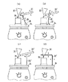
図5は本発明の実施例2とその各変形例における使用例を示す。図5(a)実施例2は本体軸方向のスライド手段25を有し、軸状部材26の下端の塊状物28を振動発生機構24に当てて、拾い上げた振動を振動伝達手段17により、先端のチップ35へ伝えている。図5(b)の変形例1もほぼ同様であるが、スライド手段25′により本体上の位置だけではなくて軸状部材26′の接続位置を変える点で相違する。図5(c)の変形例2は本体20″ではなく、振動発生機構24に立ち上げた軸状部材26″に本体20″を当てて振動を受ける使用状態を示している。図5(d)の変形例3は、棒状の本体をも有しない。この例では振動発生機構24に立ち上げた軸状部材26″に貯溜部30の容器外面を直接当てて振動を加える。実施例2とその変形例の各例においても練和物23の流出量を調整する点は前記実施例1について説明したのと同様である。
【0044】
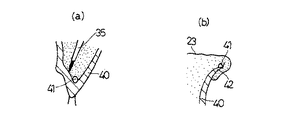
本装置により例えば鋳造冠のワックスパターン内面に埋没材を流し込むには、図6に示すように、チップ先端をパターン内面の側面には接触させないようにして、振動停止のまま最深部のみに触れさせる。ここで振動を加えると練和物23である埋没材はチップ先端まで練続して流れ下って、ワックスパターン40をその最深部から満たして行く、と同時にワックスパターン40の内面の気泡41を生じやすい箇所を軽くなぞる操作をする(図7(a)参照)。上記操作を埋没材(23)がワックスパターン40の気泡41を生じやすいマージン部42からあふれだすまで行ない(図7(b))、その後チップ先端を埋没材(23)から引き抜く。
【0045】
上記の操作を繰り返すことによりワックスパターン40が複数の場合でも、早く、容易かつ気泡を混入させずに埋没材(23)をワックスパターン内に充填することができる。またワックスパターンの咬合面のように凹凸の大きい箇所43についても(図8)、チップ35の先端を咬合面に接触させてから振動を加え、軽く延ばすように周囲に拡げて行くことにより、気泡を作らずに埋没材(23)を流し込むことができる。
【0046】
印象歯型内面への石膏の流し込み操作も、前記鋳造冠パターン内面への埋没材の流し込み操作と基本的に同様で良い。練和物23である石膏は、トレー44中の印象材45によって形成されている歯型の内面に充填され、その際にチップ35を振動停止のまま歯型の最深部まで位置させてから振動させることで、石膏を確実に誘導することができる。
【0047】
万が一残存してしまった気泡41に対しては、チップ35の柔軟な先端で内面を軽くなぞり、振動するチップ先端を直接気泡41に接触させ、浮き出させることができるのも前記と同様である。実施例1について、本発明による練和物23の流し込み操作では、従来行なわれていたテーブル上のバイブレーターの振動を使用しなくても流し込みが可能である。また埋没材や石膏等の練和物23は貯溜部30内で振動を受けるために硬化が遅延されることとなり、作業時間に少々の余裕を生む効果もある。
【0048】
【発明の効果】
本発明は以上の如く構成されかつ作用するものであるから、歯科用練和物を歯型内面の最深部等目的とする箇所に少量ずつ、しかも歯型が十分満たされるまで連続して流し込むことができ、気泡を巻き込むおそれが少なくなり、万が一残存してしまった気泡に対しては柔軟性のチップを目的箇所に接触させるので、気泡を直接吊り上げるように歯型内面から引き離し、効果的な気泡の除去が可能となり、歯型面の変形や損傷を来たすおそれがない。特に本発明では振動発生機構を内蔵しない本体にあっても内蔵する本体の場合と同様、効率良く振動を貯溜部へ伝達することができ、振動が伝達されただけでは流出口が開かない流量可変構成を有することと相俟って、作業性を著しく良好なものとすることができる、という顕著な効果を奏する。
【図面の簡単な説明】
【図1】本発明に係る歯科用練和物の流し込み装置の実施例1及び実施例2とその変形例1、2、3を示す分解斜視図。
【図2】同上装置の縦断面図。
【図3】(a)常開の流出口の開閉説明図。
(b)練和物の流動状態を示す説明図。
(c)切り込み状流出口の開閉説明図。
(d)練和物の流動状態を示す説明図。
【図4】(a)スリット状流出口の開閉説明図。
(b)練和物の流動状態を示す説明図。
(c)切り込み状と常開の流出口を組み合わせた流出口の開閉説明図。
(d)練和物の流動状態を示す説明図。
【図5】(a)実施例2における使用状態の側面説明図。
(b)同じく変形例1の側面説明図。
(c)同じく変形例2の側面説明図。
(d)同じく変形例3の側面説明図。
【図6】使用状態の1例を示す断面説明図。
【図7】(a)気泡残存部の1例を示す断面図。
(b)気泡残存部の他の例を示す断面図。
【図8】使用状態の他の例を示す断面説明図。
【図9】(a)気泡を引き離す状態の断面説明図。
(b)練和物の充填例を示す断面説明図。 [0001]
BACKGROUND OF THE INVENTION
The present invention relates to an apparatus that has a portion that can be held with one hand, and that allows vibrations generated by a vibration generating mechanism to be added to a dental kneaded product in a reservoir, thereby facilitating its pouring.
[0002]
[Prior art]
In dental technicians, it is important to pour a fluid (kneaded material) such as gypsum and investment material into the restoration parts such as crowns and inlays in the impression or the occlusal surface and the inner surface of the wax pattern. Greatly affects the quality of the product. For example, in the work of pouring a fluid as described above into the inner surface of a wax pattern, conventionally, a tapered brush, a metal instrument, or a thin wax rod is used, and a small amount of investment material is scooped off at the tip of each. The pouring operation will be repeated many times. However, there is a problem that the amount that can be scooped at a time is small, and bubbles are involved when pouring.
[0003]
In contrast, Japanese Utility Model Laid-Open No. 2-131417, a device for a dental vibrator has been proposed. In the device of the same invention, the tip of the vibrating body supported by the base portion is projected forward from the tip of the casing, and the middle portion of the vibrating body is engaged with the rotating pinion by a switching operation. In this configuration, vibration is generated. With this configuration, it is described that when the vibrating portion at the tip of the vibrating body comes into contact with the fluidized gypsum, the gypsum is vibrated, and the tooth mold is filled without any wrinkles.
[0004]
However, the vibrating body in the above device needs to be a conductive material in order to serve as part of the switch mechanism. In the specification, the vibrating body is described as a round bar-like stainless material having a diameter of about 1 mm, and other examples are not described.
[0005]
On the other hand, there is a circumstance that very precise surface reproducibility is required for taking an impression. As the impression material, agar, alginate, and rubber materials are generally used. However, these materials are easily deformed or damaged even by a slight external force. Therefore, when the vibrator of the above-mentioned device is used, scratching or rubbing the impression surface with the tip of the vibrating body made of a round bar-shaped stainless steel material may cause deformation or damage even with a rubber-based impression material that has a strong resilience. It will be easily guessed.
[0006]
In the above device, although the method of using the vibrating body in contact with the impression surface or the like has not been described, it is possible to position the tip of the vibrating body as deep as possible without touching the impression surface in a state where it is buried in gypsum. The thinner the mold, the more difficult it is, and it must be considered that the vibrating body actually touches the impression surface. This is especially true for impression surfaces where there are many irregularities in the tooth mold, such as inlay formation. For this reason, even if the round rod-shaped stainless steel vibrating body described in the above device is used, it is easy to cause deformation and damage of the impression surface, and a good result cannot be expected.
[0007]
In the wax pattern, since deformation and damage due to external force are more likely to occur than in the impression material, a more delicate operation is required for the burying operation. When this is performed by the vibrator according to the above-described device, excessively strong vibration of the stainless steel vibrating body becomes a problem. For this vibration, the vibrating body contacts the wax pattern surface, deformation in that portion, causing damage may say self-evident. Therefore, it is considered that it is practically impossible to use the vibrator of the above-mentioned device for the operation of burying the wax pattern because it takes a high risk.
[0008]
Further, the amount of gypsum that can be skimmed by the stainless steel vibrating body in the above device is largely the same as that of the conventional method as long as there is no difference in form. Therefore, it is difficult to expect to fill even a small tooth mold at a time, and it is necessary to scoop the plaster from the kneader several times and pour it into the tooth mold. The opportunity to get involved will not change.
[0009]
In addition, the removal of bubbles also has a problem in the case of the vibrator of the above-mentioned device. In the device of this vibrator, it is supposed that vibration is directly applied to the object to be vibrated (that is, gypsum, etc.) to eliminate bubbles by eliminating vibration, but apart from the bubbles contained in gypsum, the inner surface of the tooth mold, This is because it is particularly difficult to lift the bubbles adhering to the corners away from the tooth mold.
[0010]
According to the experience of the present inventor, it is not possible to expect a great effect because bubbles are lifted up simply by vigorously vibrating the plaster, and the tip of something must be touched to separate the bubbles. Needless to say, the vibrator of the above-mentioned device is not suitable for touching bubbles.
[0011]
In clinical practice, the inner surface of the impression tooth mold has a complicated shape with many irregularities, and there are also portions where the impression material is thin. In particular, when a rubber-based impression material that does not wet well is used as the impression material, the operation of pouring gypsum without generating bubbles is very difficult. For this reason, conventionally, it has been necessary to insert a thin object into the gypsum and gently trace or lightly poke a portion where air bubbles are easily generated to lift the air bubbles away from the inner surface of the tooth mold.
[0012]
[Problems to be solved by the invention]
The present invention has been made in view of the above circumstances, and the problem is that it is possible to pour a flowable dental kneaded material such as gypsum and investment material into a target portion little by little until it is sufficiently filled. In addition, as much as possible, the kneaded product can be poured into the target place without entraining bubbles.
[0013]
Another object of the present invention is to remove bubbles remaining when the kneaded product is poured into the tooth mold and remains attached to the tooth mold surface without causing deformation or damage to the tooth mold surface. It is to be.
[0014]
[Means for Solving the Problems]
In order to solve the above problems, the present invention relates to a dental kneaded product pouring device, wherein vibration generated by a vibration generating mechanism is transmitted by a vibration transmitting means including a kneaded product reservoir, and the flow of the reservoir is reduced. A means is provided in which a flexible tip for supplying the kneaded material flowing out from the outlet to the target location is provided at the end of the vibration transmitting means.
[0015]
The vibration generating mechanism can have a structure provided inside the main body. The above problem can also be solved by a configuration including a vibration generating mechanism arranged outside the main body. In this case, vibration is transmitted to the flexible chip by a vibration transmitting means having a contact portion with the vibration generating mechanism. To do.
[0016]
DETAILED DESCRIPTION OF THE INVENTION
The dental kneading apparatus according to the present invention is a device that generates a necessary vibration using a vibration generating mechanism and can promote the flow of the dental kneaded material to be filled in a tooth mold or the like by the vibration. is there. In the present invention, the dental kneaded product is a general term for dental plaster, investment material, and refractory model material.
[0017]
The apparatus according to the present invention has a portion of a size and shape that can be operated by holding, for example, a pencil in one hand. The vibration generating mechanisms that can be used in the present invention are roughly classified into a built-in type and a non-built-in type. In any system, the vibration generating mechanism and the flexible tip are connected by vibration transmission means including a kneaded product reservoir, and the vibration in the vibration generating mechanism vibrates the kneaded product in the reservoir. On the other hand, even when the container of the kneaded product storage part becomes the main part of the vibration transmission means without having a part called the main body, vibration is taken in by contact with the vibration generating mechanism, and the kneading part of the storage part etc. The Japanese product will be vibrated.
[0018]
In the case of the non-built-in type, a desktop vibrator used in a dental technician can be used for the vibration generating mechanism. In this case, the vibration transmitting means includes a member that effectively or efficiently transmits the vibration of the desktop vibrator to the main body. As this member, a shaft-like member that is easy to transmit vibration and is easy to handle is suitable. The shaft-shaped member refers to an elongated rod-shaped member or a hollow tubular object. The shaft-like member is also applied to the case where the container of the kneaded product storage part is the main part of the vibration transmitting means.
[0019]
The shaft-like member has a higher vibration transmission efficiency as the hard material, and the efficiency decreases as the soft material. The vibration transmission efficiency also changes depending on whether it is linear or curved. The present invention assumes a case where a hard material having no flexibility is used and a case where a material having moderate flexibility and good vibration transmission efficiency is used. When using a hard material, it is desirable to connect the main body and the vibration transmitting means in an adjustable manner, whereas when using an appropriate flexible material , there is almost no operational problem even with a fixed connection method. .
[0020]
In order to change the way of transmission in the vibration transmitting means, the distance from the vibration generating mechanism to the tip at the end can be adjusted. Further, it is possible to add an adjusting means for giving a left and right movement to the vibration transmitting means, and it is possible to add an adjusting means for giving a back and forth movement to the vibration transmitting means. Further, if a portion larger than the shaft-shaped member shaft portion such as a spherical shape or a lump shape is provided at the tip of the shaft-shaped member that contacts the vibration generating mechanism, the operability can be improved.
[0021]
The kneaded material is allowed to flow out from the outlet provided in the reservoir. The outlet may be always open with a constant opening area, or may be a variable opening area type that is closed and opened by operation when not operated. As an outlet that can be opened and closed, a slit-like structure can be provided that expands the opening when a deforming force is applied to the reservoir, and reduces the opening when the deforming force is not applied. Moreover, it is good also as a structure which combined the notch | incision and opening.
[0022]
【Example】
Hereinafter, the present invention will be described in more detail with reference to the illustrated embodiments. 1 and 2, a
[0023]
The first embodiment having the built-in type
[0024]
The illustrated example has a configuration in which the vibration of the
[0025]
The degree of vibration amplification can be adjusted by moving the motor position. For example, the closer the motor is to the central part of the main body, the smaller the amplitude of the
[0026]
The vibration transmission means 17 is a means and configuration for transmitting the vibration generated by the
[0027]
For example, a cup-shaped or corn-shaped member having the same size and shape as a filling container such as an investment material can be used as the
[0028]
The second embodiment having the non-built-in type
[0029]
The sliding means 25 by moving in the longitudinal direction of the
[0030]
In the figure,
[0031]
As the sliding means 25 ′, a method may be employed in which a hole is formed in the
[0032]
As a second modification of the second embodiment having a rod-shaped main body, there is also shown a system in which a shaft-
[0033]
As in the case of the first embodiment, the second embodiment and the first and second modifications thereof are also provided with a connecting means for the kneaded
[0034]
As another example of the non-built-in type, the third modification will be described. The third modification substantially includes only the
[0035]
It
[0036]
[0037]
The cut-
[0038]
A
[0039]
In the illustrated embodiment, a
[0040]
Next, the operation of the casting device for dental mixture of the present invention will be described together with the method of use.
[0041]
First, for example, a kneaded dental kneaded
[0042]
When using the
[0043]
FIG. 5 shows a usage example in the second embodiment of the present invention and its modifications. FIG. 5 (a)
[0044]
In order to pour the investment material into the inner surface of the wax pattern of the casting crown, for example, as shown in FIG. 6, the tip of the tip is not brought into contact with the side surface of the inner surface of the pattern as shown in FIG. . When vibration is applied here, the investment material, which is the kneaded
[0045]
By repeating the above operation, even when there are a plurality of
[0046]
The operation of pouring gypsum into the inner surface of the impression tooth mold may be basically the same as the operation of pouring the investment material into the inner surface of the cast crown pattern. The plaster which is the kneaded
[0047]
In the same way as described above, the
[0048]
【The invention's effect】
Since the present invention is configured and operates as described above, the dental mixture is poured into the target portion such as the deepest part of the inner surface of the tooth mold in small amounts and continuously until the tooth mold is sufficiently filled. Since there is less risk of entrainment of bubbles, and a bubble that remains in the unlikely event that a flexible tip is brought into contact with the target location, it is pulled away from the inner surface of the tooth mold so that the bubbles are lifted up directly. Can be removed, and there is no risk of deforming or damaging the tooth mold surface. In particular, in the present invention, even in a main body that does not have a vibration generating mechanism, as in the case of the main body having a built-in vibration, the vibration can be efficiently transmitted to the storage portion, and the flow rate variable that does not open the outlet only by transmitting the vibration. Combined with the configuration, there is a remarkable effect that workability can be remarkably improved.
[Brief description of the drawings]
FIG. 1 is an exploded perspective view showing a first embodiment and a second embodiment of a dental kneading apparatus according to the present invention, and
FIG. 2 is a longitudinal sectional view of the apparatus.
FIG. 3A is an explanatory view of opening and closing of a normally open outlet.
(B) Explanatory drawing which shows the fluid state of a kneaded material.
(C) Opening and closing explanatory view of the cutout outlet.
(D) Explanatory drawing which shows the fluid state of a kneaded material.
FIG. 4A is an explanatory view of opening and closing of a slit-like outlet.
(B) Explanatory drawing which shows the fluid state of a kneaded material.
(C) Open / close explanatory drawing of the outflow port which combined the notch form and the normally open outflow port .
(D) Explanatory drawing which shows the fluid state of a kneaded material.
5A is an explanatory side view of a usage state in
(B) Side explanatory drawing of the
(C) Side explanatory drawing of the
(D) Side explanatory drawing of the
FIG. 6 is a cross-sectional explanatory view showing an example of a usage state.
FIG. 7A is a cross-sectional view showing an example of a bubble remaining portion.
(B) Sectional drawing which shows the other example of a bubble residual part.
FIG. 8 is an explanatory cross-sectional view showing another example of the usage state.
FIG. 9A is a cross-sectional explanatory view showing a state in which bubbles are pulled apart.
(B) Cross-sectional explanatory drawing which shows the example of filling of kneaded material.
Claims (7)
Priority Applications (2)
| Application Number | Priority Date | Filing Date | Title |
|---|---|---|---|
| JP11376699A JP4222681B2 (en) | 1999-04-21 | 1999-04-21 | Dental blending device |
| US09/556,674 US6340299B1 (en) | 1999-04-21 | 2000-04-21 | Device for pouring dental mixture |
Applications Claiming Priority (1)
| Application Number | Priority Date | Filing Date | Title |
|---|---|---|---|
| JP11376699A JP4222681B2 (en) | 1999-04-21 | 1999-04-21 | Dental blending device |
Publications (2)
| Publication Number | Publication Date |
|---|---|
| JP2000300585A JP2000300585A (en) | 2000-10-31 |
| JP4222681B2 true JP4222681B2 (en) | 2009-02-12 |
Family
ID=14620611
Family Applications (1)
| Application Number | Title | Priority Date | Filing Date |
|---|---|---|---|
| JP11376699A Expired - Lifetime JP4222681B2 (en) | 1999-04-21 | 1999-04-21 | Dental blending device |
Country Status (2)
| Country | Link |
|---|---|
| US (1) | US6340299B1 (en) |
| JP (1) | JP4222681B2 (en) |
Families Citing this family (12)
| Publication number | Priority date | Publication date | Assignee | Title |
|---|---|---|---|---|
| US6620162B2 (en) * | 2001-07-20 | 2003-09-16 | Spineology, Inc. | Device for inserting fill material particles into body cavities |
| US7901407B2 (en) * | 2002-08-02 | 2011-03-08 | Boston Scientific Scimed, Inc. | Media delivery device for bone structures |
| US20040191720A1 (en) * | 2003-02-13 | 2004-09-30 | Allan Coopersmith | Vibrating dental device and method |
| JP2005072742A (en) * | 2003-08-21 | 2005-03-17 | Sony Corp | Encoding apparatus and encoding method |
| US7261718B2 (en) * | 2003-09-11 | 2007-08-28 | Skeletal Kinetics Llc | Use of vibration with polymeric bone cements |
| US7261717B2 (en) * | 2003-09-11 | 2007-08-28 | Skeletal Kinetics Llc | Methods and devices for delivering orthopedic cements to a target bone site |
| US8118812B2 (en) | 2004-03-09 | 2012-02-21 | Skeletal Kinetics, Llc | Use of vibration in composite fixation |
| US9707024B2 (en) | 2004-03-09 | 2017-07-18 | Skeletal Kinetics, Llc | Use of vibration in composite fixation |
| US20140134572A1 (en) * | 2005-12-15 | 2014-05-15 | Coltene Ag | Polymeric Material for Taking a Dental Impression and Method Thereof |
| US20070172792A1 (en) * | 2005-12-15 | 2007-07-26 | Stephan Lampl | Method of dental impression taking |
| EP1983917B1 (en) | 2006-01-27 | 2014-06-25 | Spinal Ventures, LLC | Low pressure delivery system for delivering a solid and liquid mixture into a target site for medical treatment |
| DE102009013000A1 (en) * | 2009-03-13 | 2010-09-16 | Kaltenbach & Voigt Gmbh | Hand device for dispensing a pasty filling material |
Family Cites Families (8)
| Publication number | Priority date | Publication date | Assignee | Title |
|---|---|---|---|---|
| US2526735A (en) * | 1945-12-06 | 1950-10-24 | Union Carbide & Carbon Corp | Powder dispensing apparatus |
| US2953282A (en) * | 1957-06-19 | 1960-09-20 | Edwin F Peterson | Motor driven vibrator |
| US3898739A (en) * | 1973-02-16 | 1975-08-12 | Donald W Gayso | Vibrating dental packer |
| US4153403A (en) * | 1977-11-18 | 1979-05-08 | Schneider Howard S | Machine for automatically making plaster slurry and dispensing it to dental molds |
| US4270675A (en) * | 1979-10-29 | 1981-06-02 | United Technologies Corporation | Powder feed apparatus |
| US5125837A (en) * | 1988-01-06 | 1992-06-30 | Dentsply Management Corp. | Apparatus and method for therapeutic lavage and scaling of teeth |
| JPH0662383B2 (en) | 1988-11-11 | 1994-08-17 | 御木本製薬株式会社 | Method for manufacturing cosmetic raw materials |
| DE4447669B4 (en) * | 1994-02-27 | 2005-12-08 | Hahn, Rainer, Dr.Med.Dent. | Use of a suspension which serves to transmit sound between an ultrasonically stressed working tip and a material to be processed |
-
1999
- 1999-04-21 JP JP11376699A patent/JP4222681B2/en not_active Expired - Lifetime
-
2000
- 2000-04-21 US US09/556,674 patent/US6340299B1/en not_active Expired - Fee Related
Also Published As
| Publication number | Publication date |
|---|---|
| JP2000300585A (en) | 2000-10-31 |
| US6340299B1 (en) | 2002-01-22 |
Similar Documents
| Publication | Publication Date | Title |
|---|---|---|
| JP4222681B2 (en) | Dental blending device | |
| AU2008308890B2 (en) | Oral care implement having an adjustable mass centroid | |
| CN101137334B (en) | Interproximal dental tool | |
| US6726477B2 (en) | Apparatus for improving the registration and articulation of dental stone replicas | |
| ATE493079T1 (en) | ORAL CARE DEVICE | |
| JP6511579B1 (en) | Automatic toothpaste | |
| JP2013116191A (en) | Facial treatment instrument | |
| JP6855078B2 (en) | Dental vibrating device | |
| KR200447443Y1 (en) | Dental Grinding Machine | |
| GB2346088A (en) | Disposable articulator having tray support with opening which accepts a projection from a tray | |
| JP4222657B2 (en) | Dental blending device | |
| GB2373448B (en) | Dental apparatus for recording the interdental relationship of anterior teeth | |
| KR200369308Y1 (en) | Dental Impression Trays | |
| JP2007105190A (en) | Oral cavity management apparatus | |
| EP1499258B1 (en) | Dental impression dam system | |
| JP2006239368A (en) | Oral cavity and tooth cleaning apparatus | |
| KR200437249Y1 (en) | Investment Investment Brush for Small Investment Casting | |
| JP4541972B2 (en) | Dental hand instrument | |
| KR20200111658A (en) | Vibration apparatus for dental care | |
| KR100597336B1 (en) | Dental impression tray | |
| CN220424000U (en) | An accessory filling tool for bracketless invisible braces | |
| JP2004321477A (en) | Medical clinics and foot controllers for medical clinics | |
| CA2324799A1 (en) | Lingual blocker | |
| US984796A (en) | Dental impression-cup. | |
| JP2001112786A (en) | Impression molding tray |
Legal Events
| Date | Code | Title | Description |
|---|---|---|---|
| A621 | Written request for application examination |
Free format text: JAPANESE INTERMEDIATE CODE: A621 Effective date: 20060207 |
|
| A131 | Notification of reasons for refusal |
Free format text: JAPANESE INTERMEDIATE CODE: A131 Effective date: 20080520 |
|
| A521 | Written amendment |
Free format text: JAPANESE INTERMEDIATE CODE: A523 Effective date: 20080722 |
|
| TRDD | Decision of grant or rejection written | ||
| A01 | Written decision to grant a patent or to grant a registration (utility model) |
Free format text: JAPANESE INTERMEDIATE CODE: A01 Effective date: 20081104 |
|
| A01 | Written decision to grant a patent or to grant a registration (utility model) |
Free format text: JAPANESE INTERMEDIATE CODE: A01 |
|
| A61 | First payment of annual fees (during grant procedure) |
Free format text: JAPANESE INTERMEDIATE CODE: A61 Effective date: 20081118 |
|
| R150 | Certificate of patent or registration of utility model |
Free format text: JAPANESE INTERMEDIATE CODE: R150 |
|
| FPAY | Renewal fee payment (event date is renewal date of database) |
Free format text: PAYMENT UNTIL: 20111128 Year of fee payment: 3 |
|
| FPAY | Renewal fee payment (event date is renewal date of database) |
Free format text: PAYMENT UNTIL: 20111128 Year of fee payment: 3 |
|
| FPAY | Renewal fee payment (event date is renewal date of database) |
Free format text: PAYMENT UNTIL: 20121128 Year of fee payment: 4 |
|
| FPAY | Renewal fee payment (event date is renewal date of database) |
Free format text: PAYMENT UNTIL: 20121128 Year of fee payment: 4 |
|
| FPAY | Renewal fee payment (event date is renewal date of database) |
Free format text: PAYMENT UNTIL: 20131128 Year of fee payment: 5 |
|
| R250 | Receipt of annual fees |
Free format text: JAPANESE INTERMEDIATE CODE: R250 |
|
| R250 | Receipt of annual fees |
Free format text: JAPANESE INTERMEDIATE CODE: R250 |
|
| R250 | Receipt of annual fees |
Free format text: JAPANESE INTERMEDIATE CODE: R250 |
|
| R250 | Receipt of annual fees |
Free format text: JAPANESE INTERMEDIATE CODE: R250 |
|
| R250 | Receipt of annual fees |
Free format text: JAPANESE INTERMEDIATE CODE: R250 |
|
| EXPY | Cancellation because of completion of term |