JP4222689B2 - Reflector and method for manufacturing reflector - Google Patents
Reflector and method for manufacturing reflector Download PDFInfo
- Publication number
- JP4222689B2 JP4222689B2 JP17972199A JP17972199A JP4222689B2 JP 4222689 B2 JP4222689 B2 JP 4222689B2 JP 17972199 A JP17972199 A JP 17972199A JP 17972199 A JP17972199 A JP 17972199A JP 4222689 B2 JP4222689 B2 JP 4222689B2
- Authority
- JP
- Japan
- Prior art keywords
- sheet
- base
- retroreflective
- base sheet
- width direction
- Prior art date
- Legal status (The legal status is an assumption and is not a legal conclusion. Google has not performed a legal analysis and makes no representation as to the accuracy of the status listed.)
- Expired - Lifetime
Links
- 238000004519 manufacturing process Methods 0.000 title claims description 10
- 238000000034 method Methods 0.000 title description 13
- 239000000758 substrate Substances 0.000 claims abstract description 12
- 239000000463 material Substances 0.000 claims description 86
- 238000004049 embossing Methods 0.000 claims description 33
- 238000005452 bending Methods 0.000 claims description 13
- 239000011347 resin Substances 0.000 claims description 12
- 229920005989 resin Polymers 0.000 claims description 12
- 229910052751 metal Inorganic materials 0.000 claims description 9
- 239000002184 metal Substances 0.000 claims description 9
- 239000011248 coating agent Substances 0.000 claims description 3
- 238000000576 coating method Methods 0.000 claims description 3
- 230000032798 delamination Effects 0.000 abstract 1
- 238000004140 cleaning Methods 0.000 description 28
- 230000000694 effects Effects 0.000 description 11
- 239000000853 adhesive Substances 0.000 description 10
- XLYOFNOQVPJJNP-UHFFFAOYSA-N water Substances O XLYOFNOQVPJJNP-UHFFFAOYSA-N 0.000 description 10
- 230000001070 adhesive effect Effects 0.000 description 9
- 230000001771 impaired effect Effects 0.000 description 8
- -1 polyethylene Polymers 0.000 description 7
- 239000010410 layer Substances 0.000 description 6
- 229920003023 plastic Polymers 0.000 description 6
- 239000004033 plastic Substances 0.000 description 6
- 239000007787 solid Substances 0.000 description 6
- 239000012790 adhesive layer Substances 0.000 description 5
- 230000005484 gravity Effects 0.000 description 5
- 239000004820 Pressure-sensitive adhesive Substances 0.000 description 4
- 239000011247 coating layer Substances 0.000 description 4
- 230000000052 comparative effect Effects 0.000 description 4
- 238000005507 spraying Methods 0.000 description 4
- 239000004698 Polyethylene Substances 0.000 description 3
- 239000004743 Polypropylene Substances 0.000 description 3
- 229910052782 aluminium Inorganic materials 0.000 description 3
- 230000000704 physical effect Effects 0.000 description 3
- 229920000573 polyethylene Polymers 0.000 description 3
- 229920001155 polypropylene Polymers 0.000 description 3
- 238000012545 processing Methods 0.000 description 3
- 238000009751 slip forming Methods 0.000 description 3
- 239000003522 acrylic cement Substances 0.000 description 2
- XAGFODPZIPBFFR-UHFFFAOYSA-N aluminium Chemical compound [Al] XAGFODPZIPBFFR-UHFFFAOYSA-N 0.000 description 2
- 239000011324 bead Substances 0.000 description 2
- 238000010586 diagram Methods 0.000 description 2
- 229920001971 elastomer Polymers 0.000 description 2
- 229920002635 polyurethane Polymers 0.000 description 2
- 239000004814 polyurethane Substances 0.000 description 2
- 239000004800 polyvinyl chloride Substances 0.000 description 2
- 229920000915 polyvinyl chloride Polymers 0.000 description 2
- 238000003825 pressing Methods 0.000 description 2
- 239000007921 spray Substances 0.000 description 2
- 239000004925 Acrylic resin Substances 0.000 description 1
- 229920000178 Acrylic resin Polymers 0.000 description 1
- RYGMFSIKBFXOCR-UHFFFAOYSA-N Copper Chemical compound [Cu] RYGMFSIKBFXOCR-UHFFFAOYSA-N 0.000 description 1
- YCKRFDGAMUMZLT-UHFFFAOYSA-N Fluorine atom Chemical compound [F] YCKRFDGAMUMZLT-UHFFFAOYSA-N 0.000 description 1
- 241000135309 Processus Species 0.000 description 1
- BQCADISMDOOEFD-UHFFFAOYSA-N Silver Chemical compound [Ag] BQCADISMDOOEFD-UHFFFAOYSA-N 0.000 description 1
- GWEVSGVZZGPLCZ-UHFFFAOYSA-N Titan oxide Chemical compound O=[Ti]=O GWEVSGVZZGPLCZ-UHFFFAOYSA-N 0.000 description 1
- 230000001154 acute effect Effects 0.000 description 1
- 230000015572 biosynthetic process Effects 0.000 description 1
- 239000002775 capsule Substances 0.000 description 1
- 229910052802 copper Inorganic materials 0.000 description 1
- 239000010949 copper Substances 0.000 description 1
- 238000011161 development Methods 0.000 description 1
- 239000000428 dust Substances 0.000 description 1
- 239000000806 elastomer Substances 0.000 description 1
- 238000010894 electron beam technology Methods 0.000 description 1
- 229920006332 epoxy adhesive Polymers 0.000 description 1
- 238000011156 evaluation Methods 0.000 description 1
- 239000004744 fabric Substances 0.000 description 1
- 229910052731 fluorine Inorganic materials 0.000 description 1
- 239000011737 fluorine Substances 0.000 description 1
- 230000004927 fusion Effects 0.000 description 1
- PCHJSUWPFVWCPO-UHFFFAOYSA-N gold Chemical compound [Au] PCHJSUWPFVWCPO-UHFFFAOYSA-N 0.000 description 1
- 229910052737 gold Inorganic materials 0.000 description 1
- 239000010931 gold Substances 0.000 description 1
- 239000012943 hotmelt Substances 0.000 description 1
- 238000002347 injection Methods 0.000 description 1
- 239000007924 injection Substances 0.000 description 1
- 238000012067 mathematical method Methods 0.000 description 1
- 239000000155 melt Substances 0.000 description 1
- 239000000123 paper Substances 0.000 description 1
- 239000011941 photocatalyst Substances 0.000 description 1
- 229920001225 polyester resin Polymers 0.000 description 1
- 239000004645 polyester resin Substances 0.000 description 1
- 229920000139 polyethylene terephthalate Polymers 0.000 description 1
- 239000005020 polyethylene terephthalate Substances 0.000 description 1
- 229920000098 polyolefin Polymers 0.000 description 1
- 229920005672 polyolefin resin Polymers 0.000 description 1
- 230000001681 protective effect Effects 0.000 description 1
- 230000003014 reinforcing effect Effects 0.000 description 1
- 239000013464 silicone adhesive Substances 0.000 description 1
- 229910052709 silver Inorganic materials 0.000 description 1
- 239000004332 silver Substances 0.000 description 1
- OGIDPMRJRNCKJF-UHFFFAOYSA-N titanium oxide Inorganic materials [Ti]=O OGIDPMRJRNCKJF-UHFFFAOYSA-N 0.000 description 1
- 238000002834 transmittance Methods 0.000 description 1
- 230000007306 turnover Effects 0.000 description 1
- 230000037303 wrinkles Effects 0.000 description 1
Images

Classifications
-
- G—PHYSICS
- G02—OPTICS
- G02B—OPTICAL ELEMENTS, SYSTEMS OR APPARATUS
- G02B5/00—Optical elements other than lenses
- G02B5/12—Reflex reflectors
- G02B5/122—Reflex reflectors cube corner, trihedral or triple reflector type
- G02B5/124—Reflex reflectors cube corner, trihedral or triple reflector type plural reflecting elements forming part of a unitary plate or sheet
-
- E—FIXED CONSTRUCTIONS
- E01—CONSTRUCTION OF ROADS, RAILWAYS, OR BRIDGES
- E01F—ADDITIONAL WORK, SUCH AS EQUIPPING ROADS OR THE CONSTRUCTION OF PLATFORMS, HELICOPTER LANDING STAGES, SIGNS, SNOW FENCES, OR THE LIKE
- E01F9/00—Arrangement of road signs or traffic signals; Arrangements for enforcing caution
- E01F9/60—Upright bodies, e.g. marker posts or bollards; Supports for road signs
- E01F9/658—Upright bodies, e.g. marker posts or bollards; Supports for road signs characterised by means for fixing
- E01F9/669—Upright bodies, e.g. marker posts or bollards; Supports for road signs characterised by means for fixing for fastening to safety barriers or the like
-
- Y—GENERAL TAGGING OF NEW TECHNOLOGICAL DEVELOPMENTS; GENERAL TAGGING OF CROSS-SECTIONAL TECHNOLOGIES SPANNING OVER SEVERAL SECTIONS OF THE IPC; TECHNICAL SUBJECTS COVERED BY FORMER USPC CROSS-REFERENCE ART COLLECTIONS [XRACs] AND DIGESTS
- Y10—TECHNICAL SUBJECTS COVERED BY FORMER USPC
- Y10T—TECHNICAL SUBJECTS COVERED BY FORMER US CLASSIFICATION
- Y10T428/00—Stock material or miscellaneous articles
- Y10T428/23—Sheet including cover or casing
-
- Y—GENERAL TAGGING OF NEW TECHNOLOGICAL DEVELOPMENTS; GENERAL TAGGING OF CROSS-SECTIONAL TECHNOLOGIES SPANNING OVER SEVERAL SECTIONS OF THE IPC; TECHNICAL SUBJECTS COVERED BY FORMER USPC CROSS-REFERENCE ART COLLECTIONS [XRACs] AND DIGESTS
- Y10—TECHNICAL SUBJECTS COVERED BY FORMER USPC
- Y10T—TECHNICAL SUBJECTS COVERED BY FORMER US CLASSIFICATION
- Y10T428/00—Stock material or miscellaneous articles
- Y10T428/24—Structurally defined web or sheet [e.g., overall dimension, etc.]
- Y10T428/2419—Fold at edge
- Y10T428/24215—Acute or reverse fold of exterior component
-
- Y—GENERAL TAGGING OF NEW TECHNOLOGICAL DEVELOPMENTS; GENERAL TAGGING OF CROSS-SECTIONAL TECHNOLOGIES SPANNING OVER SEVERAL SECTIONS OF THE IPC; TECHNICAL SUBJECTS COVERED BY FORMER USPC CROSS-REFERENCE ART COLLECTIONS [XRACs] AND DIGESTS
- Y10—TECHNICAL SUBJECTS COVERED BY FORMER USPC
- Y10T—TECHNICAL SUBJECTS COVERED BY FORMER US CLASSIFICATION
- Y10T428/00—Stock material or miscellaneous articles
- Y10T428/24—Structurally defined web or sheet [e.g., overall dimension, etc.]
- Y10T428/24777—Edge feature
Landscapes
- Physics & Mathematics (AREA)
- General Physics & Mathematics (AREA)
- Optics & Photonics (AREA)
- Engineering & Computer Science (AREA)
- Architecture (AREA)
- Civil Engineering (AREA)
- Structural Engineering (AREA)
- Road Signs Or Road Markings (AREA)
- Optical Elements Other Than Lenses (AREA)
- Push-Button Switches (AREA)
- Transition And Organic Metals Composition Catalysts For Addition Polymerization (AREA)
Abstract
Description
【0001】
【発明の属する技術分野】
本発明は、基材シートとその表面に固定された再帰反射シートとを含んでなる積層体からなり、トンネル内の壁、ガードレール、標識などの物体に貼り付けられて、物体の夜間の視認性を高めるために使用される反射材に関し、特に、略平坦な基部と、基部にて隔てられ、かつ再帰反射シート側に突出した複数の凸部とを有する反射面を有し、広入射角特性(広い範囲の入射角光に対して観察者が視認可能なこと)にすぐれた反射材に関する。
【0002】
【従来の技術】
従来から、再帰反射シートによって被覆されている略平坦な基部と、同じく再帰反射シートによって被覆された複数の凸部とを含む反射面を有する、反射シートやプレート等の反射材は知られている。例えば、実公昭62−41804号公報には、貼紙防止を目的として表面に突起を形成した反射シートが開示されている。この反射シートは、例えば、再帰反射シートを基材シートの表面に貼り付けた後、基材シート背面側からエンボス加工を施すことにより、表面に突起を形成して作製できる。しかしながら、貼紙防止を目的として形成された突起の寸法は、通常、比較的小さく(例えば、幅2mm、高さ1mm)する必要があり、また、低い入射角(反射面に対する法線に近い方向)から高い入射角(反射面に対して水平に近い方向)までの広い範囲にわたる角度の入射光線に対する反射特性、すなわち、広入射角反射特性にすぐれた反射シートとして用いるための凸部の寸法や配列は、この公報には示唆されていない。
【0003】
また、国際公開番号WO97/01677号および同WO97/01678号には、エンボス加工により製造されたものではないが、再帰反射シートで被覆された、反射性の壁状凸部と平坦面とを備えてなる再帰反射材が開示されている。この反射材では、広入射角反射特性が改良される様に、凸部の寸法や配列を決めることもできる。また、上記壁状凸部は上記平坦面の周囲を囲む様に連続して形成される。なお、平坦面の周囲を囲む様に連続して形成された壁状凸部は、上記平坦面に付着した水滴や固体状異物を、容易に除去するのを比較的困難にする。
【0004】
一方、特開平10―333616号には、基材シートと、その基材シートの表面に固定された再帰反射シートとを含んでなる積層体にエンボス加工を施し、再帰反射シートによって被覆されている略平坦な基部と、再帰反射シートによって被覆され、基部を介して離間配置された複数の凸部とを有する反射面を形成してなる、反射プレートが開示されている。上記複数の凸部は、規則的に繰り返された幾何学平面図形状のパターンを形成する様に配列されている。なお、この公報には、上記凸部が、基部を介して離間配置され、かつ上記平坦面の周囲を囲む様に連続して形成された壁状凸部ではない実施形態が開示されている。この様な形態では、上記平坦面に付着した水滴や固体状異物を除去することが非常に容易である。
【0005】
上記特開平10―333616号に開示されている様に、広入射角反射特性にすぐれたシート状またはプレート状の反射材を形成するには、反射性凸部が所定の寸法および配列パターンを有することが必須である。このことは、特に、比較的高い入射角(例えば、反射面の法線に対して70度以上)の光線に対する反射特性を向上させるためには重要である。一方、屋外で使用される標識の構成部材として利用される場合は、洗浄操作(または清浄操作)により、反射面に付着した粉塵などの固体状異物の除去が容易であり、使用中に(トンネル内壁やガードレールに固定された状態で)、十分な反射輝度の回復が可能なこと(すなわち、屋外使用特性)も要求される。
【0006】
【発明が解決しようとする課題】
ところで、上記の様な洗浄操作(または清浄操作)は、通常、人が洗浄装置を用いて行うのが効果的である。この様な洗浄装置は、反射材の反射面に高圧で水を噴きつけたり、ブラシ等の清浄部材で反射面を擦ったりして行う。例えば、反射材がトンネル内壁表面に固定された場合、この内壁を洗浄する高圧で水を噴きつける洗浄車によって、内壁と同時に反射材の反射面も洗浄される。
しかしながら、基材シートと再帰反射シートとを積層した反射材では、上記の様な洗浄操作によって、再帰反射シートの辺縁部(反射面の面内方向における端に位置する縁部分)が、基材シートからめくれ上がるおそれが大であった。特に、再帰反射シートが、長さ方向と幅方向とを有する場合、相対的に長い寸法を有する幅方向における端部でのめくれが顕著になる傾向が見られた。
したがって、本発明の目的は、洗浄操作によって再帰反射シートの端部がめくれ上がり、基材シート表面から剥離することを効果的に防止できる、反射材および同反射材の製造方法を提供することにある。
【0007】
【課題を解決するための手段】
本発明者らは、上記課題を解決するために種々検討した結果、基材シートと、上記基材シートの一の面に被覆した再帰反射シートとを有する反射材であって、略平坦な基部と、上記基部にて隔てられ、かつ上記再帰反射シート側に突出した複数の凸部とを備え、少なくとも物体表面に固定された状態にて、該基材シートの縁が該再帰反射シートの縁を包み込むように、該基材シートの縁を折り返すことにより、上記基材シートと上記再帰反射シートとの剥離を防止した反射材により、上記課題を達成できることを見いだして本発明を完成させたのである。上記の反射材は、上記基材シート及び上記再帰反射シートの双方が長さ方向と幅方向とを有し、上記基材シートの幅方向における少なくとも一方の縁を、上記基材シートの再帰反射シート被覆面側に折り返したものであってもよい。
【0008】
さらに、(a)上記基材シートとして、延伸性の金属または樹脂からなる平らな基材シートを用意し、(b)上記基材シートの一の面に、幅方向長さが、上記基材シートの幅方向長さより短く、上記基材シートに固定したときに、上記基材シートの幅方向の縁に上記基材シートの幅方向に沿って延長された折り曲げ可能部分を有する様に、再帰反射シートを固定して積層体を形成し、(c)上記折り曲げ可能部分を上記基材シートの再帰反射シート被覆面側に向けて折り曲げ、上記再帰反射シートの縁を被覆する様に、折返し部を形成した後、(d)上記基材シートの他の面側から複数の突起を備えるエンボスツールをその積層体に押し当ててエンボス加工し、凸部を形成する反射材の製造方法により上記課題を達成できることを見いだして、本発明を完成させたのである。
【0009】
なお、本明細書において、前記再帰反射シートの縁(端部及びその近傍)が、前記基材シートの縁(端部及びその近傍)を折り曲げて形成された、すなわち基材シートの一部分からなる折返し部で被覆された状態であることが好適である。なぜならば、通常、本発明で使用される再帰反射シートは、ビーズ等の反射要素の表面を被覆する光透過性フィルムからなる被覆層を有するか、または、光透過性フィルムからなる反射要素(キューブコーナープリズム等)を有する。これらの再帰反射シートは、上記の様にして比較的鋭角に折り曲げると、光透過性フィルムが破損するおそれがある。したがって、再帰反射シート自体を折り曲げることのない、上記の形態が好適である。なお、上記の形態では、反射材が物体表面に固定された後に折り返し部を形成することもできるが、通常、反射材が物体表面に固定される前に、折り返し部を形成しておく。
【0010】
なお、基材シートは、通常、幅方向寸法よりも相対的に大きな寸法の長さ方向を有する。しかしながら、本発明の効果を損なわない限り、幅方向と長さ方向とがほぼ同じ寸法であっても良い。再帰反射シートも、通常、幅方向よりも相対的に大きな寸法の長さ方向を有するが、本発明の効果を損なわない限り、幅方向と長さ方向とがほぼ同じ寸法であっても良い。また、この様な寸法の基材シートまたは/および再帰反射シートから形成された反射材も同様に、通常、幅方向よりも相対的に大きな寸法の長さ方向を有するが、本発明の効果を損なわない限り、幅方向と長さ方向とがほぼ同じ寸法であっても良い。
【0011】
一方、反射性の凸部の形は、本発明の効果を損なわない限り特に限定されないが、好適には、再帰反射シートの幅方向の一端から他端に向けて連続する凸条が好適である。この様な凸条は、長さ方向に対して略垂直な反射側面(基部に対して隆起した反射シートの表面)を有し、長さ方向に大略沿って入射した光を広い反射側面で反射することができる。したがって、トンネル内壁やガードレール等の物体上に、道路の延在方向と、反射材の長さ方向とを略平行にして反射材を配置した場合の反射輝度を、特に効果的に高めることができる。
【0012】
上記の様な凸条を有する反射材は、例えば、次の様な方法で製造するのが好適である。すなわち、(a)延伸性の金属または樹脂からなる平らな基材シートを用意し、(b)上記基材シートの一の面に、幅方向長さが、上記基材シートの幅方向長さより短く、上記基材シートに固定したときに、上記基材シートの幅方向の端部近傍に上記基材シートの幅方向に沿って延長された折り曲げ可能部分を有する様に、再帰反射シートを固定して積層体を形成し、(c)上記折り曲げ可能部分を上記基材シートの再帰反射シート被覆面側に向けて折り曲げ、上記再帰反射シートの端部およびその近傍を被覆する様に、折返し部を形成した後、(d)上記基材シートの他の面側から複数の突起を備えるエンボスツールをその積層体に押し当ててエンボス加工し、凸部を形成する。
この方法では、エンボス加工(凸条等の凸部を設けるための加工)に先だって基材シートの折返し加工を行う。すなわち、再帰反射シートおよび基材シートの端部近傍を平坦な状態して、折返し加工を行うので、反射面の凸部が基材シートの折り曲げを邪魔することがなく、折返し操作が容易になる。なお、凸部が上記の様な凸条ではなく、反射面上に規則的に配置された複数の点の上に配置される等、凸部が再帰反射シートの端部に存在せず、基材シートの折り曲げの際に邪魔にならない場合は、エンボス加工後に折返し加工を行うこともできる。
【0013】
【発明の実施の形態】
以下、本発明をその実施形態に基づき、具体的に説明する。
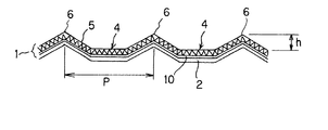
図1は、本発明に係る反射材の一実施態様を示す側断面図であり、反射材は、基材シート(2)と、基材シート(2)の一面を被覆した再帰反射シート(1)を有している。また、反射材は、略平坦な基部(4)と、基部(4)にて隔てられ、かつ再帰反射シート(1)側に突出した複数の凸部(6)とを備えている。そして、この反射材は、少なくとも物体表面に固定された状態にて、辺縁部の少なくとも一部において、一方のシート〔(1)又は(2)〕の縁が他方のシート〔(2)又は(1)〕の縁を包み込むように、上記一方のシートの縁を折り返すことにより、基材シート(2)と再帰反射シート(1)との剥離を防止するものである。
【0014】
以下、本発明の反射材を構成する各部材について、詳しく説明する。
(反射材)
本発明による反射材は、広入射角反射材に分類される。「広入射角反射材」とは、反射材を水平に置いた場合、その水平面の法線近傍の方向から入射された光の反射輝度が十分なレベルであり、かつ反射材の水平面近傍の斜め方向から入射された光の反射輝度も視認可能なレベル(例えば1.5CPL以上)である反射材を意味する。換言すれば、本発明による反射材は、反射材の水平面の法線近傍から水平面近傍まで入射角度を傾けていったときに、反射輝度が極端に低下せず(例えば1CPL以下にならない)、広い範囲の角度の入射光線に対して十分な反射性能を有する反射材である。本発明の反射材が十分な反射性能を発揮する入射角の範囲は、少なくとも0〜75度であり、好適な形態では0〜86度の範囲も可能である。なお、この角度は、反射材の基部平面の法線からの角度である。
【0015】
次式(I)は、凸部の寸法と配列を好適にに設計するための、各パラメータの関係を表す。なお、凸部の配置および寸法がこの式に従う場合、凸部は、1つのまたは複数の幾何学平面図形を規則的に繰り返して形成したパターンに従い、互いに離れて配置される。各凸部が互いに離れており、かつ、独立しているので、反射面に付着した固体状異物の除去が容易になる。
【0016】
【数1】
0.05<h/P<0.60 (I)
(式中のPは、互いに隣接する2つの凸部間距離(=ピッチ)であり、hは、基部の表面から測定した凸部の高さである。)
【0017】
なお、上記Pが複数規定される場合は、最も大きなPを採用するものとする。例えば、点状の凸部(6)が、ひし形の4つの頂点上に配置される場合、このPは、ひし形の対角線に沿った2つの凸部(6)の頂点間距離をP(ピッチ)として採用する。また、凸部(6)が、再帰反射シートの幅方向の一端から他端に向けて連続する凸条である場合、図1に示したように、凸条(6)の垂直方向横断面(再帰反射シート(1)の長さ方向に沿った断面)における、2つの凸部(6)の頂点間距離Pである。なお、式(I)にしたがって、上記の様な凸条の配置および寸法を決定する場合、凸条は、幾何学平面図形として、長方形を規則的に繰り返して形成したパターンに従い、長方形の2つの頂点をまたいで配置されていると見なすこともできる。すなわち、長方形の互いに平行な2辺上に凸条が配置され、それらは互いに離れて、独立している。
【0018】
式(I)のh/P値が0.05以下の場合、比較的高入射角の光線に対する反射輝度が低下するおそれがあり、反対に式(I)のh/P値が0.60以上の場合は、十分な反射輝度が得られる入射角を高く(例えば、70度以上に)設計できないおそれがある。この様な観点から、式(I)のh/P値は、好適には0.07〜0.47、特に好適には0.08〜0.30の範囲である。
式(I)のh/Pは、凸部において十分な輝度で反射可能な最大入射角をθとした場合、角度(90−θ)の正接、すなわちtan(90−θ)にほぼ等しい。したがって、式(I)の下限値「0.05」および上限値「0.60」は、θの下限が約60度、上限が約87度であることとほぼ同等の意味を持つ。
Pは通常4mm以上である。これより小さいと、高入射角の光線に対する反射特性を向上させることができないおそれがあり、反対に大きすぎても凸部の配置密度が小さくなり、高入射角の反射特性の向上効果が低下するおそれがある。この様な観点から、Pの好適な範囲は8〜30mm、特に好適な範囲は10〜25mmである。
【0019】
一方、hは通常0.5mm以上である。これより小さいと、高入射角の光線に対する反射特性を向上させることができないおそれがあり、反対に大きすぎると、凸部(6)の形成の際に、再帰反射シート(1)を破損するおそれがある。この様な観点から、hの好適な範囲は1〜10mm、特に好適な範囲は1.5〜5mmである。垂直方向横断面(図1参照)における、凸部と、それと隣接する基部(4)との境界点間寸法(すなわち、凸部の幅)は、通常5mm以上である。小さすぎると、高入射角の光線に対する反射特性を向上させることができないおそれがある。一方、凸部幅が大きすぎても凸部(6)の配置密度が小さくなり、やはり、高入射角の反射特性の向上効果が低下するおそれがある。この様な観点から、この幅の好適な範囲は10〜40mm、特に好適な範囲は15〜35mmである。
【0020】
凸部(6)の配列は、1つのまたは複数の幾何学平面図形を規則的に繰り返して形成したパターンに従い、その幾何学図形のすべての頂点に互いに分離して凸部を配置するのが好適である。各凸部(6)は、その底部図形(基部との境界面における水平断面)の重心(円の場合は中心)が、幾何学図形の頂点(凸部の配置中心)と略一致する様に配置される。図形の重心は、数学的手法によって求めることができる。幾何学図形の形状は、式(I)を満たす限りにおいて特に限定されない。例えば、基部(4)を含む水平面内において、長方形、五角形、六角形等の多角形や、2つの三角形を、それぞれの1辺が接する様に配置して形成したひし形である。また、配列パターン中に複数の幾何学平面図形が存在し、複数のPの値が決まる場合があるが、高入射角反射特性の向上のためには、すべてのP値が式(I)を満たすのが好ましい。
【0021】
凸部(6)の配置密度は、通常、互いに隣接する2つの凸部間に配置された基部(4)の最小水平方向寸法(例えば、図1における再帰反射シート(1)の長さ方向に沿った寸法)が、通常、2〜20mm、好適には3〜15mmの範囲になる様に決定される。配置密度が小さすぎても大きすぎても高入射角における反射特性が低下するおそれがある。凸部(6)の垂直方向横断面における形状として、例えば、半円、半楕円、半円または半楕円の頂部を水平方向に切り取った形、三角形、台形、四角形等の形状が採用できる。また、複数の凸部は、本発明の効果を損なわない限り、異なる2以上の立体形状のものを含んでいても良い。
【0022】
エンボス加工により形成された凸部(6)は、基材シートの裏面側に空洞を有する。この場合、基材シートの厚みにもよるが、外力による凸部の変形が懸念される場合は、上記空洞を樹脂等で充填して補強するのが好適である。この様な樹脂は、例えば、紫外線、電子線、熱、湿気等により硬化可能なものが使用できる。この様な硬化性樹脂は、空洞に充填した後、硬化させることにより補強効果が発揮される。
凸部(6)が凸条である場合、通常その凸条は、基材シート(2)の長さ方向に沿って、基部(4)を介して離間配置される。この様な場合、凸条の長さ方向は、通常、基材シートの幅方向と略平行になる様にする。または、光の入射方向に対して直交する様にするのが好適である。これにより、反射材の反射輝度を効果的に高めることができる。例えば、光が基材シート(すなわち反射材)の長さ方向と略平行に入射される場合、凸条の長さ方向は、通常、基材シートの幅方向と略平行であるのが好適である。一方、光が反射材の長さ方向から所定の角度だけずれた入射角で入射される場合、凸条の長さ方向は、基材シートの幅方向と平行でないのが良く、光の入射方向に対して直交する様にするのが好適である。また、異なる複数の入射角をもって光が入射する場合、凸条は直線状であるよりは、多数の角を持つ折れ線または曲線状であるのが良い。
【0023】
(基材シート)
基材シート(2)は、通常、金属またはプラスチックからなる。中でも、延伸性にすぐれる軟質金属または軟質プラスチックが好適である。エンボス加工(および折り返し加工)が容易であり、凸部(6)および折返し部(3)を容易に形成することができる。軟質金属としては、アルミニウム、銅、銀、金などが好適である。また、軟質プラスチックとしては、ポリエチレン、ポリプロピレン、ポリ塩化ビニル、ポリウレタンなどが好適である。基材シートの厚みや引張強さなどの物性は、本発明の効果を損なわない限り、特に限定されない。しかしながら、反射材を後述する様なエンボス加工および折り返し加工により形成する場合は、基材シートの物性を次のように選択するのが好適である。厚みの好適な範囲は、金属の場合で0.05〜2mm、プラスチックの場合で0.1〜5mmである。厚みが薄すぎると、エンボス加工による凸部の形成の際に基材シートが破損するおそれがあり、反対に厚すぎると、エンボス加工による凸部の形成が困難になるおそれがある。引張強さは、好適には1〜15kg/mm2、特に好適には2〜12kg/mm2である。引張強さが1kg/mm2未満であると、エンボス加工または折り返し加工の際に基材シートが破損するおそれがあり、反対に15kg/mm2を超えると加工が困難になるおそれがある。
【0024】
(再帰反射シート)
本発明で使用される再帰反射シート(1)は、例えば、光透過性フィルムからなる被覆層を有し、ビーズ等の反射要素の表面が露出していないカプセルレンズまたは封入レンズタイプが使用できる。また、キューブコーナープリズム等のプリズム反射要素を裏面に有する光透過性フィルムを用い、裏面側にシール層を積層し、そのシール層によりプリズム反射要素をカプセル状に封入して形成した、プリズム型再帰反射シートも使用できる。プリズム型反射シートでは、光透過性フィルムの表面(プリズム反射要素を持たない面、通常平坦である)が反射面(5)である。上記光透過性フィルムは、アクリル樹脂、ポリエステル樹脂、フッ素系樹脂、ポリオレフィン系樹脂、ポリ塩化ビニル系樹脂などが使用できる。光透過性フィルムの全光透過率は、通常80%以上である。
【0025】
被覆層を有する反射シートとしては、例えば、3M(株)製のスコッチライト(商標)「品番:#580」、「#3810J」、「#1570」などを挙げることができる。また、プリズム型反射シートとしては、3M社製のスコッチライト(商標)「品番:#981」などを挙げることができる。反射シートの破断伸び、破断強度、厚みなどの物性は、本発明の効果を損なわない限り、特に限定されない。しかしながら、反射材をエンボス加工により形成する場合は、次のように選択するのが好適である。破断伸びは、好適には5〜300%、特に好適には10〜280%である。破断伸びが300%を超えると、エンボス加工の際に反射面にしわが発生するおそれがあり、反対に5%未満であると、エンボス加工が困難になるおそれがある。破断強度は、好適には1.0〜10.0kg/25mm、特に好適には3.0〜7.0kg/25mmである。破断強度が1.0kg/25mm未満であると、エンボス加工の際に反射シートが破損するおそれがあり、反対に10kg/25mmを超えると、エンボス加工が困難になるおそれがある。厚みの好適な範囲は、10〜750μmである。10μm未満であると、エンボス加工の際に反射シートが破損するおそれがあり、反対に750μmを超えると、エンボス加工が困難になるおそれがある。
【0026】
基材シート(2)に再帰反射シート(1)を固定するには、例えば、接着剤(10)が使用できる。接着剤(10)は、例えば、アクリル系接着剤、ポリオレフィン系接着剤、ポリウレタン系接着剤、シリコーン系接着剤、エポキシ系接着剤などを使用する。接着剤は、感圧性接着剤、感熱性接着剤(ホットメルトを含む)、硬化型接着剤などが使用できる。好適には感圧性接着剤である。感圧性接着剤は流動性が高いので、エンボス加工による凸部の形成が容易になるからである。通常、接着剤(10)は、層状に基材シートと反射シートとの間に配置され、その層の厚みは、通常5〜50μmである。
【0027】
(接着層)
基材シートの背面(反射シートが積層されていない面)には、所望により接着層を設けることができる。接着層は、反射材をガードレール等の物体に貼り付けるために用いる。この様な接着層の接着剤には、前述のものと同様の接着剤が使用できる。接着層は、通常ライナーにより保護される。ライナーは、ポリエチレン、ポリプロピレン等の樹脂シートと紙とを貼り合わせた剥離紙、ポリエチレンテレフタレート、ポリエチレン、ポリプロピレン等の樹脂からなるフィルムが好適である。
【0028】
(反射材の製造)
本発明の反射材は、エンボス加工による凸部(6)の形成操作を含む方法で製造するのが好適である。所定の形状、寸法および配列を有する凸部を正確に形成することができるからである。エンボス加工は、所定の形状、寸法および配列の突起を複数備えるエンボスツールを、基材シートの背面側から押し当てて行う。突起の形状、寸法および配列は、反射材の凸部のそれらに対応する様に設計する。エンボス加工時の圧力は、通常1〜100kg/cm2、好適には20〜80kg/cm2である。圧力は、機械的プレス、減圧プレスなどのプレス操作により加える。エンボスツールとしては、上記突起を表面に配置したプレートまたはロールなどから構成される第1のツールと、再帰反射シートの表面側に当接する第2のツールの組を使用することができる。第2のツールとしては、第1のツールの突起を受容できる凹部を備えたものや、あるいは第1のツールが基材シートの裏面側から押し当てられたときに変形可能な材料からなる表面が平坦なものなどが使用できる。後者のタイプの、第2のツール(表面が平坦なツール)の材料は、ゴム、エラストマーなどが使用できる。
【0029】
また、エンボス加工による製造方法において、前述の様に、基材シート(2)の表面および背面に、それぞれ、再帰反射シート(2)、およびライナーで保護された粘着剤層とを備えた積層体を形成した後、その積層体のライナーの上から複数の突起を備えるエンボスツールを押し当てて凸部を形成する場合も、同様の条件およびエンボスツールを使用する。また、再帰反射シート(1)の被覆層の表面に文字、図案等の表示を印刷した後、エンボス加工を行っても良い。この他、本発明の反射材は、予め凸部が形成された基材シートの上に再帰反射シート重ねた後、減圧下で基材シートと反射シートとを圧着する方法でも製造することができる。
【0030】
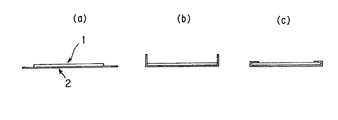
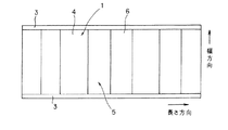
一方、再帰反射シートの端部を保護する折返し部(3)の形成操作を含む製造方法は、例えば、図2に示す様にして行う。まず、基材シート(2)として延伸性の金属または樹脂からなる平らな基材シートを用意する。次に、基材シート(2)の表面に、再帰反射シート(1)を固定して積層体を形成する。このとき、再帰反射シート(1)の幅方向長さは、基材シート(2)の幅方向長さより小さく、基材シートは、再帰反射シートの幅方向の端部が固定された部分から前記基材シートの幅方向に沿って延長された折り曲げ可能部分を有する様にする。図3に示される様に、折り返し部(3)は、再帰反射シート(1)の幅方向の両端部を被覆するのが好適である。したがって、図2に示したように、再帰反射シート(1)の長さ方向と、基材シート(2)の長さ方向とを略一致させ、基材シートの幅方向中央部に再帰反射シートを固定し、基材シートの幅方向両端に折り曲げ可能部分を形成するのが良い。この様にして形成した折り曲げ可能部分を、基材シートの表面側に向けて折り曲げ、再帰反射シートの端部およびその近傍を被覆した折返し部(3)を形成する。折り曲げ加工は、人の手で、またはベンダー等の機械で行うことができる。折り返し部(3)は、図2に示したように、反射シートの表面(反射面)に密着し、折り返し部との間に隙間ができない様にするのが好適である。反射材を屋外で使用した場合、水滴や固体状異物の侵入を防ぎ、折返し部の耐久性を高めるからである。
【0031】
折り返し部の幅方向寸法(図示の場合、基材シートの幅方向に沿った寸法)は、本発明の効果を損なわない限り特に限定されない。通常2〜30mm、好適には5〜20mmである。折り返し部の幅方向寸法が小さすぎると、洗浄操作の際に折り返し部(3)がめくれあがるおそれがあり、反対に大きすぎると、露出した反射面(5)(折り返し部で被覆されていない部分)の面積が小さくなり、輝度が低下するおそれがある。基材シート(2)が金属から形成される場合、基材シートは展延性(または塑性変形性)を有するので、折り曲げ加工後の折返し部は、その状態を容易に保つことができる。しかしながら必要に応じ、折返し部(3)を反射面(5)に接着することもできる。また、基材シートが軟質プラスチックから形成される場合、基材シートはある程度の弾性を有し、折り曲げ加工後の折返し部(3)が弾性回復し、反射面(5)から浮いてくる場合がある。その場合、必要に応じ、折返し部を反射面に接着(融着を含む)することもできる。
【0032】
折返し部(3)は、通常、再帰反射シートの長さ方向に沿って連続して延在する。しかしながら、本発明の効果を損なわない限り、反射シートの長さ方向に沿って不連続に配置されても良い。不連続に配置する場合、例えば、基部(4)の部分のみに配置することもできる。また、図3に示したように、折り返し部の開放端は、直線状であるが、波線、鋸歯状、櫛状等、非直線形であっても良い。この開放端が非直線形の場合、反射面の露出面積を可及的に大きくすることができる点で好適である。この様な場合、凸部の部分の、折り返し部の寸法(図3の場合、基材シートの幅方向に沿った寸法)が、基部(4)の部分のそれよりも小さくなる様にするのが好適である。
また、折り返し部は、再帰反射シートの、長さ方向における1つまたは2つの端部も被覆することもできる。
【0033】
(反射材の用途)
本発明の反射材は、例えば、自動車等の車両のヘッドライトにより比較的高入射角度で光が照射される、道路脇やトンネル内の壁の表面に固定される、視線誘導部材(delineator)や交通標識として特に有用に使用できる。また、ガードレール、看板、表示板などの物体表面に固定して使用し、それらの夜間視認性を高めることができる。すなわち、この様な物体表面に反射材を備えつけることにより、比較的遠方からでも、その物体をドライバー等の観察者が視認することができる。上記物体へ反射材を固定するには、前述の接着等を用いる他、ビスやボルト等の固定手段も使用できる。
【0034】
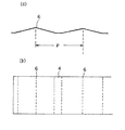
また、反射材の反射面を清浄な状態に保つためには、定期的に洗浄を行うのが良いが、洗浄後、次の洗浄が行われるまでの間に、汚損された表面を自然の力でも清浄に保てればなお良い。そこで、酸化チタン等の光触媒を含む光透過性の保護膜で反射面を被覆したり、図4に示される様な自浄部材(7)を利用するのが好適である。図4に示される自浄部材(7)は、布帛、フィルム等の薄片からなり、その一端(固定端)を反射材の反射面上に固定し、自然の、または車両が通過したときに発生する風の圧力で、はためく様にしてある。この様な薄片がはためいたとき、反射面を擦り、自浄効果を発揮するものである。なお、図4の例では、道路の延在方向と、反射材(基材シートおよび再帰反射シート)の長さ方向とをが略平行になる様に、反射材を配置してある。したがって、上記薄片は、風圧が作用しないときは、鉛直方向(反射材の幅方向)に沿って垂れ下がる。この場合、薄片の固定端は、反射材の幅方向、重力方向における上端に固定され、風圧が作用しないときは、薄片の自由端は、反射材の重力方向における下端に通常位置する。薄片は、光不透過性であっても良いが、好適には光透過性である。光透過性の薄片は、例えば、透明フィルム、メッシュ、ネット等、光透過性材料からなるものや、光不透過性の薄片に、1以上の透視窓を設けたものである。また、薄片に代えて、ロープ、糸等の線材も使用できる。
【0035】
図4に示す様に、自浄部材(7)は、風圧が作用しないときは、反射面の基部(4)のみを覆う様に配置し、凸部表面(反射側面)は覆わない様にするのが好適である。通常、本発明の反射材を視線誘導部材等として用いる場合、比較的高い入射角光を反射し、観察者がそれを視認する。したがって、基部よりも凸部の反射側面からの反射光が、視認性を高めるのに有効に作用する。したがって、上述の様に、自浄部材を配置するのが好適である。なお、自浄部材の固定は、図4に示す様に、折返し部と再帰反射シートとの間で固定端を挟持する様にして行うのが好適である。反射材から自浄部材が脱落するのを効果的に防止できる。また、自浄部材の固定端をピンなどで点固定し、振り子の様に揺動可能にすることもできる。
【0036】
自浄部材(7)の長さ(固定端(8)から自由端(9)までの距離)は、特に限定されない。例えば図示の様に、凸部が幅方向に沿って離間配置された凸条である場合、好適には、固定端が位置する基部の幅方向端部から、その基部と隣接する凸条の頂点(稜線)の重力方向最下端までの距離と同じかそれ以上である。
【0037】
【実施例】
以下、実施例と比較例を挙げて、本発明をさらに説明するが、本発明は、これらの例により何ら限定的に解釈されるものではない。
(実施例)
基材シートとして軟質アルミニウム(東洋アルミニウム(株)製「品番:A1N30H−O」を用い、再帰反射シートとして3M(株)製のプリズム型反射シート(品番)#981を用いた。軟質アルミニウムの厚みは0.08mm、引張強さは約8kg/mm2であり、反射シートの厚みは170μm、破断伸びは200%、破断強度は4.8kg/25mmであった。再帰反射シート(1)と基材シート(2)とは、反射シートの背面に設けられたアクリル系粘着剤の層を介して接着し、再帰反射シートと基材シートとからなる積層体を作製した。なお、後述する折り曲げ加工により折返し部(3)となる、余りしろ(折り曲げ可能部分)が、基材シートの幅方向の両端部に形成される様に基材シートと反射シートとを積層した。
上記の様にして得られた積層体に、まず、図2に模式的に示した縁曲げ(折り曲げ)加工を施し、図3に示した折り曲げ可能部分を、基材シートの表面側に向けて折り曲げ、再帰反射シートの端部およびその近傍を被覆した折返し部を形成した。折り曲げ加工は、機械(ベンダー)を用いて行った。折り返し部(3)は、反射シートの表面(反射面)に密着させ、折り返し部との間に隙間ができない様にした。
【0038】
続いて、折り曲げ加工後の積層体にエンボス加工を施し、本例の反射材を完成させた。なお、エンボスツールの複数の突起を、基材シート背面側(反射シート面に対する反対面)に押し当てて行った。エンボス加工は、突起を有する第1のツールと、第1のツールの突起を受容可能な凹部を備えた第2のツールとを組み合わせたをツールを用い、エンボス圧力を約70kg/mm2にして行った。凸条と基部からなる幾何学的模様を図5(a)(b)に示す。この例では、凸部(6)は、基材シートの幅方向(すなわち、完成した反射材の幅方向)に沿って、互いに平行に延在する複数の凸条であった。また、凸部の幅は25mm、P(ピッチ)は15mm、h(高さ)は2.5mmであった。なお、反射材の長さ方向寸法(長さ)は50cm、幅方向寸法(幅)は20cmであった。
【0039】
(比較例)
折返し部を設けない以外は実施例1と同様にして、本例の反射材を作製した。(実施例の評価)
まず、実施例および比較例の反射材を、地面に対して垂直な壁の表面に固定した。それぞれの反射材の幅方向端部およびその近傍に、高圧洗車装置を用いて水をスプレー状に噴きつけ、端部に反射シートの剥離が生じるかどうか確認した。なお、水の噴きつけ条件は、水圧80kg/cm2で、噴射口と反射材端面との距離は30cm、噴きつけ時間1分間であった。その結果、端部における反射シート剥離について、目視で確認したところ、実施例では、水の噴きつけ前後で変化は見られず、反射シートの剥離は生じなかった。一方、比較例では、水の噴きつけ後に反射シートの剥離が認められた。
【0040】
【発明の効果】
本発明に係る反射材は、少なくとも物体、例えば、トンネル内壁等の表面に固定された状態で、上記再帰反射シートの幅方向における少なくとも一方の端部は、上記基材シートによって被覆されるているので、定期的に行われる洗浄操作によっても、再帰反射シートの端部がめくれ上がり、基材シート表面から剥離することを効果的に防止できることとなる。
【図面の簡単な説明】
【図1】 本発明に係る反射材の一実施態様を示す側断面図である。
【図2】 (a)、(b)および(c)は、本発明に係る反射材の製造工程における縁曲げ加工の工程を示す模式図である。
【図3】 本発明に係る反射材の製造に使用する再帰反射シートの展開図である。
【図4】 本発明に係る反射材の製造に使用する再帰反射シートに自浄部材を取り付けた状態を示す模式図である。
【図5】 (a)は、本発明に係る反射材の一実施態様の断面の模式図、(b)は、同反射材の幾何学模様を示す模式図である。
【符号の説明】
1…再帰反射シート、2…基材シート、3…折り返し部、4…再帰反射プレートの基部、5…再帰反射プレートの反射面、6…再帰反射プレートの凸部(凸条)、7…自浄部材、8…自浄部材の固定端、9…自浄部材の自由端、P…互いに隣接する2つの凸部間距離、h…基部の表面から測定した凸部の高さ。[0001]
BACKGROUND OF THE INVENTION
The present invention comprises a laminate comprising a base sheet and a retroreflective sheet fixed to the surface thereof, and is attached to an object such as a wall in a tunnel, a guardrail, a sign, etc., and the visibility of the object at night In particular, it has a reflective surface having a substantially flat base portion and a plurality of convex portions separated from the base portion and projecting toward the retroreflective sheet, and has a wide incident angle characteristic. The present invention relates to a reflective material that is excellent (that an observer can visually recognize a wide range of incident angle light).
[0002]
[Prior art]
Conventionally, a reflective material such as a reflective sheet or a plate having a reflective surface including a substantially flat base portion covered with a retroreflective sheet and a plurality of convex portions also covered with the retroreflective sheet is known. . For example, Japanese Utility Model Publication No. 62-41804 discloses a reflective sheet having protrusions on the surface for the purpose of preventing paper sticking. This reflection sheet can be produced, for example, by attaching a retroreflective sheet to the surface of the base sheet and then embossing it from the back side of the base sheet to form protrusions on the surface. However, the size of the protrusion formed for the purpose of preventing paper sticking usually needs to be relatively small (for example, 2 mm in width and 1 mm in height), and has a low incident angle (a direction close to the normal to the reflecting surface). Reflective characteristics for incident light over a wide range of angles from 1 to a high incident angle (a direction almost horizontal to the reflective surface), that is, the size and arrangement of convex portions for use as a reflective sheet with excellent wide incident angle reflective characteristics Is not suggested in this publication.
[0003]
Further, International Publication Nos. WO 97/01677 and WO 97/01678 are not manufactured by embossing, but have a reflective wall-like convex portion and a flat surface covered with a retroreflective sheet. A retroreflective material is disclosed. With this reflector, the dimensions and arrangement of the projections can be determined so that the wide incident angle reflection characteristics are improved. Further, the wall-shaped convex portion is continuously formed so as to surround the periphery of the flat surface. In addition, the wall-shaped convex part continuously formed so as to surround the periphery of the flat surface makes it relatively difficult to easily remove water droplets and solid foreign matters attached to the flat surface.
[0004]
On the other hand, in JP-A-10-333616, a laminate comprising a base sheet and a retroreflective sheet fixed to the surface of the base sheet is embossed and covered with the retroreflective sheet. There is disclosed a reflection plate formed by forming a reflection surface having a substantially flat base portion and a plurality of convex portions that are covered with a retroreflective sheet and are spaced apart via the base portion. The plurality of convex portions are arranged so as to form a pattern having a geometric plan view that is regularly repeated. Note that this publication discloses an embodiment in which the convex portions are not wall-shaped convex portions that are spaced apart from each other via a base and are continuously formed so as to surround the periphery of the flat surface. In such a form, it is very easy to remove water droplets and solid foreign matters adhering to the flat surface.
[0005]
As disclosed in the above-mentioned JP-A-10-333616, in order to form a sheet-like or plate-like reflecting material having excellent wide incident angle reflection characteristics, the reflective convex portions have predetermined dimensions and arrangement patterns. It is essential. This is particularly important for improving the reflection characteristics with respect to light rays having a relatively high incident angle (for example, 70 degrees or more with respect to the normal of the reflecting surface). On the other hand, when used as a component of a sign used outdoors, it is easy to remove solid foreign matters such as dust adhering to the reflective surface by a cleaning operation (or a cleaning operation). It is also required that the reflected brightness can be sufficiently recovered (that is, outdoor use characteristics) while being fixed to the inner wall or guardrail.
[0006]
[Problems to be solved by the invention]
By the way, it is usually effective for a person to perform the above-described cleaning operation (or cleaning operation) using a cleaning device. Such a cleaning apparatus is performed by spraying water at a high pressure on the reflecting surface of the reflecting material or rubbing the reflecting surface with a cleaning member such as a brush. For example, when the reflecting material is fixed to the inner wall surface of the tunnel, the reflecting surface of the reflecting material is cleaned at the same time as the inner wall by a cleaning vehicle that sprays water at a high pressure for cleaning the inner wall.
However, in the reflective material in which the base sheet and the retroreflective sheet are laminated, the edge portion of the retroreflective sheet (the edge portion located at the end in the in-plane direction of the reflective surface) is changed by the cleaning operation as described above. There was a great risk of turning up from the material sheet. In particular, when the retroreflective sheet has a length direction and a width direction, the tendency to turn over at the end in the width direction having a relatively long dimension was noticeable.
Therefore, an object of the present invention is to provide a reflector and a method for producing the reflector that can effectively prevent the end of the retroreflective sheet from being turned up and peeled off from the surface of the base sheet by a cleaning operation. is there.
[0007]
[Means for Solving the Problems]
As a result of various studies to solve the above-mentioned problems, the present inventors have obtained a reflective material having a base sheet and a retroreflective sheet coated on one surface of the base sheet, and a substantially flat base portion. And a plurality of convex portions separated by the base and projecting toward the retroreflective sheet, and at least fixed to the object surface , By reflecting the edge of the base material sheet so that the edge of the base material sheet wraps around the edge of the retroreflective sheet, the above problem is solved by the reflective material that prevents the base material sheet and the retroreflective sheet from peeling off. The present invention has been completed by finding out that the above can be achieved. In the reflecting material, both the base sheet and the retroreflective sheet have a length direction and a width direction, and at least one of the base sheets in the width direction. edge May be folded back to the retroreflective sheet-coated surface side of the substrate sheet.
[0008]
Furthermore, (a) a flat base sheet made of a stretchable metal or resin is prepared as the base sheet, and (b) a width direction length is formed on one surface of the base sheet. When shorter than the width direction length of the sheet and fixed to the base sheet, the width direction of the base sheet edge A retroreflective sheet is fixed to form a laminate so as to have a foldable part extending along the width direction of the base sheet, and (c) the bendable part is retroreflected by the base sheet. Bend toward the sheet coating surface, edge After forming the folded portion so as to cover the surface, (d) an embossing tool having a plurality of protrusions is pressed against the laminated body from the other surface side of the base sheet to form the convex portion. The present invention has been completed by finding that the above-mentioned problems can be achieved by the manufacturing method of the reflecting material.
[0009]
In this specification, , A state where the edge (end portion and its vicinity) of the retroreflective sheet is formed by bending the edge (end portion and its vicinity) of the base sheet, that is, covered with a folded portion made of a part of the base sheet. It is preferable that This is because the retroreflective sheet used in the present invention usually has a coating layer made of a light transmissive film covering the surface of a reflective element such as a bead or a reflective element (cube) made of a light transmissive film. Corner prism etc.). If these retroreflective sheets are bent at a relatively acute angle as described above, the light transmissive film may be damaged. Therefore, the top of the retroreflective sheet itself is not folded. Record Is preferable. The above Record In this embodiment, the folded portion can be formed after the reflecting material is fixed to the object surface, but usually the folded portion is formed before the reflecting material is fixed to the object surface.
[0010]
In addition, a base material sheet has the length direction of a dimension larger than a width direction dimension normally. However, as long as the effects of the present invention are not impaired, the width direction and the length direction may have substantially the same dimensions. The retroreflective sheet also usually has a length direction that is relatively larger than the width direction, but the width direction and the length direction may be substantially the same unless the effects of the present invention are impaired. Similarly, the reflective material formed from the base sheet or / and the retroreflective sheet having such a dimension generally has a length direction having a relatively larger dimension than the width direction. As long as it is not damaged, the width direction and the length direction may have substantially the same dimensions.
[0011]
On the other hand, the shape of the reflective convex portion is not particularly limited as long as the effect of the present invention is not impaired, but preferably a convex ridge that is continuous from one end to the other end in the width direction of the retroreflective sheet is suitable. . Such a ridge has a reflective side surface (surface of the reflection sheet raised with respect to the base) substantially perpendicular to the length direction, and reflects light incident along the length direction with a wide reflective side surface. can do. Therefore, it is possible to particularly effectively increase the reflection luminance when the reflecting material is arranged on an object such as a tunnel inner wall or a guard rail so that the road extending direction and the length direction of the reflecting material are substantially parallel to each other. .
[0012]
For example, the reflecting material having the above-described protrusions is preferably manufactured by the following method. That is, (a) a flat base sheet made of an extensible metal or resin is prepared, and (b) the width direction length on one surface of the base sheet is greater than the width direction length of the base sheet. Fix the retroreflective sheet so that it has a foldable part that extends along the width direction of the base sheet in the vicinity of the end of the base sheet in the width direction when short and fixed to the base sheet (C) the folded portion so as to cover the end portion of the retroreflective sheet and the vicinity thereof by bending the foldable portion toward the retroreflective sheet covering surface side of the base sheet. After forming (d), an embossing tool having a plurality of protrusions is pressed against the laminated body from the other surface side of the base sheet, and embossed to form a convex portion.
In this method, the base sheet is folded before embossing (processing for providing convex portions such as ridges). That is, since the folding process is performed with the retroreflective sheet and the vicinity of the edge of the base sheet being flat, the convex part of the reflecting surface does not interfere with the folding of the base sheet, and the folding operation is facilitated. . In addition, the convex part is not located on the end of the retroreflective sheet, such as being arranged on a plurality of points regularly arranged on the reflecting surface, instead of the convex line as described above. When the material sheet is not disturbed, folding can be performed after embossing.
[0013]
DETAILED DESCRIPTION OF THE INVENTION
Hereinafter, the present invention will be specifically described based on the embodiments.
FIG. 1 is a side sectional view showing an embodiment of a reflective material according to the present invention. The reflective material is a base sheet (2) and a retroreflective sheet (1) covering one surface of the base sheet (2). )have. Moreover, the reflecting material includes a substantially flat base (4) and a plurality of convex portions (6) separated by the base (4) and projecting toward the retroreflective sheet (1). Then, in the state where the reflecting material is fixed to at least the surface of the object, the edge of one sheet [(1) or (2)] is the other sheet [(2) or The edge of the one sheet is folded back so as to wrap the edge of (1)], thereby preventing the base sheet (2) and the retroreflective sheet (1) from peeling off.
[0014]
Hereinafter, each member which comprises the reflecting material of this invention is demonstrated in detail.
(Reflective material)
The reflective material according to the present invention is classified as a wide incident angle reflective material. “Wide incident angle reflector” means that when the reflector is placed horizontally, the reflected luminance of light incident from the direction near the normal of the horizontal plane is at a sufficient level, and the oblique angle of the reflector near the horizontal plane It means a reflective material having a level at which the reflected luminance of light incident from the direction is also visible (for example, 1.5 CPL or more). In other words, the reflective material according to the present invention does not extremely reduce the reflection luminance (for example, not lower than 1 CPL) when the incident angle is inclined from the vicinity of the normal to the horizontal surface of the reflective material to the vicinity of the horizontal surface. It is a reflective material having sufficient reflection performance with respect to incident light rays having a range of angles. The range of the incident angle at which the reflective material of the present invention exhibits sufficient reflection performance is at least 0 to 75 degrees, and in the preferred embodiment, the range of 0 to 86 degrees is also possible. This angle is an angle from the normal of the base plane of the reflector.
[0015]
The following formula (I) represents the relationship between the parameters for suitably designing the dimensions and arrangement of the convex portions. In addition, when arrangement | positioning and a dimension of a convex part follow this type | formula, a convex part is arrange | positioned mutually apart according to the pattern formed by repeating one or several geometric plane figures regularly. Since each convex part is separated from each other and independent, it is easy to remove the solid foreign matter adhering to the reflecting surface.
[0016]
[Expression 1]
0.05 <h / P <0.60 (I)
(P in the formula is the distance between two adjacent protrusions (= pitch), and h is the height of the protrusion measured from the surface of the base.)
[0017]
When a plurality of Ps are defined, the largest P is adopted. For example, when the dot-shaped convex part (6) is arranged on four vertices of the rhombus, this P is the distance between the vertices of the two convex parts (6) along the diagonal of the rhombus P (pitch). Adopt as. Moreover, when a convex part (6) is a convex line | wire continuous toward the other end from the one end of the width direction of a retroreflection sheet, as shown in FIG. It is the distance P between the vertices of the two convex portions (6) in the cross section along the length direction of the retroreflective sheet (1). In addition, when determining the arrangement and dimensions of the ridges as described above according to the formula (I), the ridges are two geometrical figures according to a pattern formed by repeating a rectangle regularly. It can also be regarded as being placed across vertices. In other words, the ridges are arranged on two parallel sides of the rectangle, and they are separated from each other and independent.
[0018]
When the h / P value of the formula (I) is 0.05 or less, there is a possibility that the reflected luminance with respect to a light beam having a relatively high incident angle may be lowered. In this case, there is a possibility that the incident angle at which sufficient reflection luminance can be obtained cannot be designed high (for example, 70 degrees or more). From such a viewpoint, the h / P value of the formula (I) is preferably in the range of 0.07 to 0.47, particularly preferably in the range of 0.08 to 0.30.
In the formula (I), h / P is substantially equal to the tangent of the angle (90-θ), that is, tan (90-θ), where θ is the maximum incident angle that can be reflected with sufficient brightness at the convex portion. Therefore, the lower limit value “0.05” and the upper limit value “0.60” of the formula (I) have substantially the same meaning as that the lower limit of θ is about 60 degrees and the upper limit is about 87 degrees.
P is usually 4 mm or more. If it is smaller than this, it may not be possible to improve the reflection characteristics with respect to light rays with a high incident angle. There is a fear. From such a viewpoint, the preferable range of P is 8 to 30 mm, and the particularly preferable range is 10 to 25 mm.
[0019]
On the other hand, h is usually 0.5 mm or more. If it is smaller than this, there is a possibility that the reflection characteristic with respect to a light having a high incident angle cannot be improved. On the other hand, if it is too large, the retroreflective sheet (1) may be damaged during the formation of the convex portion (6). There is. From such a viewpoint, a preferable range of h is 1 to 10 mm, and a particularly preferable range is 1.5 to 5 mm. In the vertical cross section (see FIG. 1), the dimension between the boundary points between the convex part and the adjacent base part (4) (that is, the width of the convex part) is usually 5 mm or more. If it is too small, there is a possibility that the reflection characteristic with respect to a light beam having a high incident angle cannot be improved. On the other hand, even if the width of the convex portion is too large, the arrangement density of the convex portions (6) is reduced, and there is a possibility that the effect of improving the reflection characteristics at a high incident angle may be lowered. From such a viewpoint, a preferable range of this width is 10 to 40 mm, and a particularly preferable range is 15 to 35 mm.
[0020]
The arrangement of the convex portions (6) is preferably such that the convex portions are separated from each other at all vertices of the geometric figure in accordance with a pattern formed by regularly repeating one or a plurality of geometric plane figures. It is. Each convex part (6) is such that the center of gravity (center in the case of a circle) of the bottom figure (horizontal cross section at the boundary surface with the base) substantially coincides with the apex of the geometric figure (arrangement center of the convex part). Be placed. The center of gravity of the figure can be obtained by a mathematical method. The shape of the geometric figure is not particularly limited as long as the formula (I) is satisfied. For example, in the horizontal plane including the base portion (4), a polygon such as a rectangle, a pentagon, and a hexagon, and a rhombus formed by arranging two triangles so that one side of each of them is in contact with each other. In addition, there may be a plurality of geometrical plane figures in the array pattern, and a plurality of P values may be determined. However, in order to improve the high incident angle reflection characteristics, all P values are represented by the formula (I). It is preferable to satisfy.
[0021]
The arrangement density of the projections (6) is usually the minimum horizontal dimension of the base (4) arranged between two adjacent projections (for example, in the length direction of the retroreflective sheet (1) in FIG. 1). Along the dimension) is usually determined to be in the range of 2-20 mm, preferably 3-15 mm. If the arrangement density is too small or too large, the reflection characteristics at a high incident angle may be deteriorated. As a shape in the vertical cross section of the convex portion (6), for example, a shape such as a semicircle, a semi-ellipse, a semi-circle or a semi-ellipse cut in the horizontal direction, a triangle, a trapezoid, a quadrangle, etc. can be adopted. Moreover, the some convex part may contain the thing of two or more different solid shapes, unless the effect of this invention is impaired.
[0022]
The convex part (6) formed by embossing has a cavity in the back surface side of a base material sheet. In this case, although depending on the thickness of the base sheet, when there is a concern about deformation of the convex portion due to external force, it is preferable to reinforce by filling the cavity with a resin or the like. As such a resin, for example, a resin that can be cured by ultraviolet rays, electron beams, heat, moisture, or the like can be used. Such a curable resin exhibits a reinforcing effect by being filled in a cavity and then cured.
When a convex part (6) is a protruding item | line, the protruding item | line is normally spacedly arranged via a base part (4) along the length direction of a base material sheet (2). In such a case, the length direction of the ridges is usually made substantially parallel to the width direction of the base sheet. Or it is suitable to make it orthogonal to the incident direction of light. Thereby, the reflective brightness | luminance of a reflecting material can be raised effectively. For example, when light is incident substantially parallel to the length direction of the base sheet (that is, the reflective material), the length direction of the ridges is usually preferably substantially parallel to the width direction of the base sheet. is there. On the other hand, when the light is incident at an incident angle shifted by a predetermined angle from the length direction of the reflective material, the length direction of the ridge should not be parallel to the width direction of the base sheet, and the light incident direction It is preferable to be orthogonal to. In addition, when light is incident at a plurality of different incident angles, the ridge is preferably a polygonal line or a curved line having a number of angles, rather than a straight line.
[0023]
(Substrate sheet)
The base sheet (2) is usually made of metal or plastic. Among these, a soft metal or a soft plastic having excellent stretchability is preferable. Embossing (and folding) is easy, and the convex portion (6) and the folded portion (3) can be easily formed. As the soft metal, aluminum, copper, silver, gold and the like are suitable. As the soft plastic, polyethylene, polypropylene, polyvinyl chloride, polyurethane and the like are suitable. The physical properties such as thickness and tensile strength of the base sheet are not particularly limited as long as the effects of the present invention are not impaired. However, when the reflecting material is formed by embossing and folding as described later, it is preferable to select the physical properties of the base sheet as follows. The preferred range of thickness is 0.05 to 2 mm for metal and 0.1 to 5 mm for plastic. If the thickness is too thin, the base sheet may be damaged when the convex portions are formed by embossing. Conversely, if the thickness is too thick, it may be difficult to form the convex portions by embossing. The tensile strength is preferably 1 to 15 kg / mm 2 , Particularly preferably 2 to 12 kg / mm 2 It is. Tensile strength is 1kg / mm 2 If it is less than the range, the substrate sheet may be damaged during embossing or folding, and conversely, 15 kg / mm. 2 If it exceeds, processing may become difficult.
[0024]
(Retroreflective sheet)
The retroreflective sheet (1) used in the present invention may be, for example, a capsule lens or an encapsulated lens type that has a coating layer made of a light transmissive film and the surface of a reflective element such as beads is not exposed. In addition, a prism-type recursion is formed by using a light-transmitting film having a prism reflection element such as a cube corner prism on the back surface, a seal layer is laminated on the back surface side, and the prism reflection element is encapsulated by the seal layer. A reflective sheet can also be used. In the prism type reflection sheet, the surface of the light transmissive film (the surface having no prism reflection element, usually flat) is the reflection surface (5). As the light transmissive film, an acrylic resin, a polyester resin, a fluorine resin, a polyolefin resin, a polyvinyl chloride resin, or the like can be used. The total light transmittance of the light transmissive film is usually 80% or more.
[0025]
Examples of the reflective sheet having a coating layer include Scotchlite (trademark) “Part No .: # 580”, “# 3810J”, “# 1570” manufactured by 3M Corporation. Examples of the prism-type reflection sheet include Scotchlite (trademark) “Product No .: # 981” manufactured by 3M. Physical properties such as breaking elongation, breaking strength and thickness of the reflective sheet are not particularly limited as long as the effects of the present invention are not impaired. However, when the reflecting material is formed by embossing, it is preferable to select as follows. The breaking elongation is preferably 5 to 300%, particularly preferably 10 to 280%. If the elongation at break exceeds 300%, wrinkles may occur on the reflecting surface during embossing. Conversely, if it is less than 5%, embossing may be difficult. The breaking strength is preferably 1.0 to 10.0 kg / 25 mm, particularly preferably 3.0 to 7.0 kg / 25 mm. If the breaking strength is less than 1.0 kg / 25 mm, the reflective sheet may be damaged during embossing. Conversely, if it exceeds 10 kg / 25 mm, embossing may be difficult. A preferable range of the thickness is 10 to 750 μm. If the thickness is less than 10 μm, the reflective sheet may be damaged during embossing. Conversely, if the thickness exceeds 750 μm, embossing may be difficult.
[0026]
In order to fix the retroreflective sheet (1) to the base sheet (2), for example, an adhesive (10) can be used. As the adhesive (10), for example, an acrylic adhesive, a polyolefin adhesive, a polyurethane adhesive, a silicone adhesive, an epoxy adhesive, or the like is used. As the adhesive, a pressure-sensitive adhesive, a heat-sensitive adhesive (including hot melt), a curable adhesive, and the like can be used. A pressure sensitive adhesive is preferred. This is because the pressure-sensitive adhesive has high fluidity, so that it is easy to form a convex portion by embossing. Usually, an adhesive agent (10) is arrange | positioned between a base material sheet and a reflective sheet in the layer form, and the thickness of the layer is 5-50 micrometers normally.
[0027]
(Adhesive layer)
If desired, an adhesive layer can be provided on the back surface (the surface on which the reflective sheet is not laminated) of the base material sheet. The adhesive layer is used for attaching the reflective material to an object such as a guardrail. As the adhesive for such an adhesive layer, the same adhesive as described above can be used. The adhesive layer is usually protected by a liner. The liner is preferably a release paper obtained by bonding a resin sheet such as polyethylene or polypropylene and paper, or a film made of a resin such as polyethylene terephthalate, polyethylene, or polypropylene.
[0028]
(Manufacture of reflective material)
The reflector of the present invention is preferably manufactured by a method including an operation of forming the convex portion (6) by embossing. This is because convex portions having a predetermined shape, size, and arrangement can be accurately formed. Embossing is performed by pressing an embossing tool having a plurality of protrusions having a predetermined shape, size, and arrangement from the back side of the base sheet. The shape, size, and arrangement of the protrusions are designed to correspond to those of the convex portions of the reflector. The pressure during embossing is usually 1-100 kg / cm 2 , Preferably 20-80 kg / cm 2 It is. The pressure is applied by a press operation such as a mechanical press or a vacuum press. As the embossing tool, a set of a first tool composed of a plate or a roll having the protrusions arranged on the surface and a second tool that comes into contact with the surface side of the retroreflective sheet can be used. As a 2nd tool, the surface provided with the recessed part which can receive the processus | protrusion of a 1st tool, or the surface which consists of a material which can deform | transform when a 1st tool is pressed from the back surface side of a base material sheet | seat. A flat one can be used. The material of the latter type of the second tool (tool having a flat surface) can be rubber, elastomer or the like.
[0029]
Moreover, in the manufacturing method by embossing, as described above, the laminate provided with the retroreflective sheet (2) and the pressure-sensitive adhesive layer protected by the liner on the front surface and the back surface of the base sheet (2), respectively. When the embossing tool having a plurality of protrusions is pressed from above the liner of the laminate to form the convex portion, the same conditions and the embossing tool are used. In addition, embossing may be performed after characters, designs, etc. are printed on the surface of the coating layer of the retroreflective sheet (1). In addition, the reflective material of the present invention can also be produced by a method in which a retroreflective sheet is stacked on a base material sheet on which convex portions are formed in advance, and then the base material sheet and the reflective sheet are pressure-bonded under reduced pressure. .
[0030]
On the other hand, the manufacturing method including the forming operation of the folded portion (3) for protecting the end portion of the retroreflective sheet is performed as shown in FIG. First, a flat base sheet made of a stretchable metal or resin is prepared as the base sheet (2). Next, the retroreflective sheet (1) is fixed to the surface of the base sheet (2) to form a laminate. At this time, the length in the width direction of the retroreflective sheet (1) is smaller than the length in the width direction of the base sheet (2), and the base sheet is from the portion where the end in the width direction of the retroreflective sheet is fixed. It is made to have the bendable part extended along the width direction of the base material sheet. As FIG. 3 shows, it is suitable for a folding | returning part (3) to coat | cover the both ends of the width direction of a retroreflection sheet (1). Therefore, as shown in FIG. 2, the length direction of the retroreflective sheet (1) and the length direction of the base sheet (2) are substantially matched, and the retroreflective sheet is placed at the center in the width direction of the base sheet. It is good to form a bendable part in the width direction both ends of a base material sheet. The foldable portion formed in this way is bent toward the surface side of the base material sheet to form a folded portion (3) covering the end portion of the retroreflective sheet and the vicinity thereof. The bending process can be performed by a human hand or a machine such as a vendor. As shown in FIG. 2, the folded portion (3) is preferably in close contact with the surface (reflecting surface) of the reflective sheet so that no gap is formed between the folded portion and the folded portion. This is because when the reflective material is used outdoors, it prevents intrusion of water droplets or solid foreign matters and improves the durability of the folded portion.
[0031]
The width direction dimension (in the case of illustration, the dimension along the width direction of a base material sheet) of a folding | turning part is not specifically limited unless the effect of this invention is impaired. Usually 2 to 30 mm, preferably 5 to 20 mm. If the widthwise dimension of the folded part is too small, the folded part (3) may be turned up during the cleaning operation. If it is too large, the exposed reflecting surface (5) (the part not covered with the folded part) ) Area is reduced, and the luminance may be reduced. When the base sheet (2) is formed from a metal, the base sheet has spreadability (or plastic deformability), and thus the folded portion after the bending process can easily maintain the state. However, if necessary, the folded portion (3) can be bonded to the reflecting surface (5). In addition, when the base sheet is formed of soft plastic, the base sheet has a certain degree of elasticity, and the folded portion (3) after the bending process may be elastically recovered and may float from the reflecting surface (5). is there. In that case, the folding | returning part can also be adhere | attached on a reflective surface (a melt | fusion is included) as needed.
[0032]
The folded portion (3) usually extends continuously along the length direction of the retroreflective sheet. However, as long as the effects of the present invention are not impaired, they may be discontinuously arranged along the length direction of the reflective sheet. When arrange | positioning discontinuously, it can also arrange | position only to the part of a base (4), for example. As shown in FIG. 3, the open end of the folded portion is linear, but it may be non-linear such as a wavy line, a sawtooth, or a comb. When the open end is non-linear, it is preferable in that the exposed area of the reflecting surface can be increased as much as possible. In such a case, the dimension of the folded part of the convex part (in the case of FIG. 3, the dimension along the width direction of the base sheet) is made smaller than that of the base part (4). Is preferred.
The folded portion can also cover one or two end portions of the retroreflective sheet in the length direction.
[0033]
(Use of reflective material)
The reflective material of the present invention is, for example, a line-of-sight guide member (delineator) fixed to a roadside or a wall surface in a tunnel that is irradiated with light at a relatively high incident angle by a headlight of a vehicle such as an automobile. It can be used particularly useful as a traffic sign. In addition, it can be used by fixing it on the surface of an object such as a guardrail, a signboard, or a display board, thereby improving the night visibility. That is, by providing a reflecting material on such an object surface, an observer such as a driver can visually recognize the object even from a relatively long distance. In order to fix the reflective material to the object, fixing means such as screws and bolts can be used in addition to the above-described adhesion.
[0034]
Moreover, in order to keep the reflecting surface of the reflecting material clean, it is preferable to periodically clean the surface. However, after the cleaning, until the next cleaning is performed, the soiled surface must be washed naturally. But it's better if you keep it clean. Therefore, it is preferable to cover the reflective surface with a light-transmitting protective film containing a photocatalyst such as titanium oxide, or to use a self-cleaning member (7) as shown in FIG. The self-cleaning member (7) shown in FIG. 4 is made of a thin piece of fabric, film, etc., and one end (fixed end) thereof is fixed on the reflecting surface of the reflector, and is generated when a natural or vehicle passes. It flutters with the wind pressure. When such a flake flakes, it rubs the reflecting surface and exhibits a self-cleaning effect. In the example of FIG. 4, the reflective material is arranged so that the road extending direction and the length direction of the reflective material (base sheet and retroreflective sheet) are substantially parallel. Therefore, when the wind pressure does not act, the thin piece hangs down along the vertical direction (the width direction of the reflecting material). In this case, the fixed end of the thin piece is fixed to the upper end in the width direction and the gravity direction of the reflector, and when the wind pressure does not act, the free end of the thin piece is normally positioned at the lower end in the gravity direction of the reflector. The flakes may be light opaque, but are preferably light transparent. The light-transmitting thin piece is, for example, one made of a light-transmitting material such as a transparent film, a mesh, or a net, or a light-impermeable thin piece provided with one or more transparent windows. Moreover, it can replace with a thin piece and can use wires, such as a rope and a thread | yarn.
[0035]
As shown in FIG. 4, when the wind pressure does not act, the self-cleaning member (7) is arranged so as to cover only the base portion (4) of the reflecting surface and does not cover the convex surface (reflecting side surface). Is preferred. Usually, when the reflective material of the present invention is used as a line-of-sight guide member or the like, a relatively high incident angle light is reflected, and an observer visually recognizes it. Therefore, the reflected light from the reflective side surface of the convex part rather than the base part effectively acts to enhance the visibility. Therefore, it is preferable to arrange the self-cleaning member as described above. In addition, as shown in FIG. 4, it is suitable to fix the self-cleaning member by sandwiching the fixed end between the folded portion and the retroreflective sheet. It is possible to effectively prevent the self-cleaning member from falling off the reflecting material. Moreover, the fixed end of the self-cleaning member can be fixed with a pin or the like so that it can swing like a pendulum.
[0036]
The length of the self-cleaning member (7) (the distance from the fixed end (8) to the free end (9)) is not particularly limited. For example, as shown in the figure, when the convex portions are spaced apart along the width direction, preferably, from the width direction end portion of the base portion where the fixed end is located, the apex of the convex stripe adjacent to the base portion It is equal to or more than the distance to the lowest edge in the gravity direction of (ridge line).
[0037]
【Example】
EXAMPLES Hereinafter, although an Example and a comparative example are given and this invention is further demonstrated, this invention is not interpreted limitedly by these examples at all.
(Example)
Soft aluminum (“Part No .: A1N30H-O” manufactured by Toyo Aluminum Co., Ltd.) was used as the base sheet, and prism type reflective sheet (Part No.) # 981 manufactured by 3M Co. was used as the retroreflective sheet. Is 0.08mm, tensile strength is about 8kg / mm 2 The thickness of the reflective sheet was 170 μm, the elongation at break was 200%, and the strength at break was 4.8 kg / 25 mm. The retroreflective sheet (1) and the base material sheet (2) are bonded via an acrylic adhesive layer provided on the back surface of the reflective sheet to produce a laminate composed of the retroreflective sheet and the base material sheet. did. In addition, the base material sheet and the reflective sheet were laminated | stacked so that the margin (foldable part) used as the folding | turning part (3) by the bending process mentioned later may be formed in the both ends of the width direction of a base material sheet.
First, the laminate obtained as described above is subjected to edge bending (bending) processing schematically shown in FIG. 2, and the bendable portion shown in FIG. 3 is directed to the surface side of the base sheet. The folded part which coat | covered the edge part of the bending and retroreflection sheet | seat, and its vicinity was formed. The bending process was performed using a machine (bender). The folded portion (3) was brought into close contact with the surface (reflecting surface) of the reflecting sheet so that no gap was formed between the folded portion.
[0038]
Subsequently, the laminated body after the bending process was embossed to complete the reflective material of this example. In addition, it carried out by pressing the some protrusion of an embossing tool against the base material sheet back side (opposite surface with respect to a reflective sheet surface). The embossing uses a combination of a first tool having protrusions and a second tool having a recess capable of receiving the protrusions of the first tool, and the embossing pressure is about 70 kg / mm. 2 I went there. The geometric pattern which consists of a protruding item | line and a base is shown to Fig.5 (a) (b). In this example, the convex portion (6) was a plurality of convex strips extending in parallel with each other along the width direction of the base sheet (that is, the width direction of the completed reflector). Further, the width of the convex portion was 25 mm, P (pitch) was 15 mm, and h (height) was 2.5 mm. In addition, the length direction dimension (length) of the reflecting material was 50 cm, and the width direction dimension (width) was 20 cm.
[0039]
(Comparative example)
A reflector of this example was produced in the same manner as in Example 1 except that the folded portion was not provided. (Evaluation of Examples)
First, the reflective material of an Example and a comparative example was fixed to the surface of a wall perpendicular | vertical with respect to the ground. Water was sprayed in the form of a spray using a high-pressure car wash device at the width direction end of each reflector and in the vicinity thereof, and it was confirmed whether or not the reflection sheet peeled off at the end. The water spraying conditions are as follows: water pressure 80 kg / cm 2 The distance between the injection port and the end face of the reflector was 30 cm, and the spraying time was 1 minute. As a result, when the reflection sheet peeling at the end portion was visually confirmed, in the examples, no change was observed before and after the spraying of water, and peeling of the reflection sheet did not occur. On the other hand, in the comparative example, peeling of the reflective sheet was observed after water was sprayed.
[0040]
【The invention's effect】
The reflecting material according to the present invention is fixed to at least a surface of an object, for example, a tunnel inner wall, and at least one end in the width direction of the retroreflective sheet is covered with the base sheet. Therefore, even when the cleaning operation is performed regularly, it is possible to effectively prevent the end portion of the retroreflective sheet from turning up and peeling from the surface of the base sheet.
[Brief description of the drawings]
FIG. 1 is a side sectional view showing an embodiment of a reflector according to the present invention.
FIGS. 2A, 2B, and 2C are schematic views showing an edge bending process in a manufacturing process of a reflector according to the present invention. FIGS.
FIG. 3 is a development view of a retroreflective sheet used for manufacturing a reflector according to the present invention.
FIG. 4 is a schematic view showing a state in which a self-cleaning member is attached to a retroreflective sheet used for manufacturing a reflective material according to the present invention.
5A is a schematic diagram of a cross section of an embodiment of a reflective material according to the present invention, and FIG. 5B is a schematic diagram showing a geometric pattern of the reflective material.
[Explanation of symbols]
DESCRIPTION OF
Claims (3)
略平坦な基部と、該基部にて隔てられ、かつ該再帰反射シート側に突出した複数の凸部とを備え、
少なくとも物体表面に固定された状態にて、該基材シートの縁が該再帰反射シートの縁を包み込むように、該基材シートの縁を折り返すことにより、該基材シートと該再帰反射シートとの剥離を防止したことを特徴とする反射材。A reflector having a base sheet and a retroreflective sheet covering one surface of the base sheet,
A substantially flat base portion, and a plurality of convex portions separated by the base portion and projecting toward the retroreflective sheet,
In a state fixed to at least the surface of the object, as the edges of the base sheet to wrap the edges of the retroreflection sheet, by folding the edges of the substrate sheet, and the substrate sheet and the retroreflective sheet A reflective material characterized in that peeling of the film is prevented.
(b)該基材シートの一の面に、幅方向長さが、該基材シートの幅方向長さより短く、該基材シートに固定したときに、該基材シートの幅方向の縁に該基材シートの幅方向に沿って延長された折り曲げ可能部分を有する様に、再帰反射シートを固定して積層体を形成し、
(c)該折り曲げ可能部分を該基材シートの再帰反射シート被覆面側に向けて折り曲げ、該再帰反射シートの縁を被覆する様に、折返し部を形成した後、
(d)該基材シートの他の面側から複数の突起を備えるエンボスツールをその積層体に押し当ててエンボス加工し、該凸部を形成することを特徴とする請求項2に記載の反射材の製造方法。(A) As the base sheet, a flat base sheet made of a stretchable metal or resin is prepared,
(B) on one surface of the substrate sheet, the widthwise length shorter than the widthwise length of the substrate sheet, when fixed to the substrate sheet, the width direction of the edge of the substrate sheet A retroreflective sheet is fixed to form a laminate so as to have a foldable portion extending along the width direction of the base sheet,
(C) Bending the foldable part toward the retroreflective sheet coating surface side of the base sheet, and forming a folded portion so as to cover the edge of the retroreflective sheet;
(D) The reflection according to claim 2, wherein an embossing tool having a plurality of protrusions is pressed against the laminated body from the other surface side of the base sheet and embossed to form the convex portion. A method of manufacturing the material.
Priority Applications (13)
| Application Number | Priority Date | Filing Date | Title |
|---|---|---|---|
| JP17972199A JP4222689B2 (en) | 1999-06-25 | 1999-06-25 | Reflector and method for manufacturing reflector |
| CN00809448A CN1358277A (en) | 1999-06-25 | 2000-06-22 | Reflective article and method for manufacturing the same |
| BR0011895-8A BR0011895A (en) | 1999-06-25 | 2000-06-22 | Reflective article, and process for manufacturing the same |
| AU57584/00A AU5758400A (en) | 1999-06-25 | 2000-06-22 | Reflective article and method for manufacturing the same |
| AT00943058T ATE343802T1 (en) | 1999-06-25 | 2000-06-22 | REFLECTIVE OBJECT AND METHOD OF PRODUCTION THEREOF |
| DE60031534T DE60031534D1 (en) | 1999-06-25 | 2000-06-22 | REFLECTING OBJECT AND ITS MANUFACTURING PROCESS |
| EP00943058A EP1190267B1 (en) | 1999-06-25 | 2000-06-22 | Reflective article and method for manufacturing the same |
| PCT/US2000/017182 WO2001001172A1 (en) | 1999-06-25 | 2000-06-22 | Reflective article and method for manufacturing the same |
| KR1020017016562A KR100674452B1 (en) | 1999-06-25 | 2000-06-22 | Reflector and its manufacturing method |
| CA002377022A CA2377022A1 (en) | 1999-06-25 | 2000-06-22 | Reflective article and method for manufacturing the same |
| MXPA01013433A MXPA01013433A (en) | 1999-06-25 | 2000-06-22 | Reflective article and method for manufacturing the same. |
| US09/599,672 US6517923B1 (en) | 1999-06-25 | 2000-06-22 | Reflective article and method for manufacturing the same |
| NO20016287A NO20016287L (en) | 1999-06-25 | 2001-12-20 | Reflective object and method for making it |
Applications Claiming Priority (1)
| Application Number | Priority Date | Filing Date | Title |
|---|---|---|---|
| JP17972199A JP4222689B2 (en) | 1999-06-25 | 1999-06-25 | Reflector and method for manufacturing reflector |
Publications (2)
| Publication Number | Publication Date |
|---|---|
| JP2001003324A JP2001003324A (en) | 2001-01-09 |
| JP4222689B2 true JP4222689B2 (en) | 2009-02-12 |
Family
ID=16070722
Family Applications (1)
| Application Number | Title | Priority Date | Filing Date |
|---|---|---|---|
| JP17972199A Expired - Lifetime JP4222689B2 (en) | 1999-06-25 | 1999-06-25 | Reflector and method for manufacturing reflector |
Country Status (13)
| Country | Link |
|---|---|
| US (1) | US6517923B1 (en) |
| EP (1) | EP1190267B1 (en) |
| JP (1) | JP4222689B2 (en) |
| KR (1) | KR100674452B1 (en) |
| CN (1) | CN1358277A (en) |
| AT (1) | ATE343802T1 (en) |
| AU (1) | AU5758400A (en) |
| BR (1) | BR0011895A (en) |
| CA (1) | CA2377022A1 (en) |
| DE (1) | DE60031534D1 (en) |
| MX (1) | MXPA01013433A (en) |
| NO (1) | NO20016287L (en) |
| WO (1) | WO2001001172A1 (en) |
Families Citing this family (25)
| Publication number | Priority date | Publication date | Assignee | Title |
|---|---|---|---|---|
| JP2004116029A (en) * | 2002-09-24 | 2004-04-15 | Three M Innovative Properties Co | Reflective article |
| US20040146677A1 (en) * | 2003-01-24 | 2004-07-29 | 3M Innovative Properties Company | Flexible reflective sleeve |
| KR100612979B1 (en) * | 2004-08-17 | 2006-08-14 | 주식회사 엘지화학 | Retroreflective sheet having excellent seating properties on curved surfaces and its manufacturing method |
| US7121155B2 (en) * | 2004-12-29 | 2006-10-17 | 3M Innovative Properties Company | Pressure indicating structure |
| BRPI0500848A (en) | 2005-01-10 | 2006-09-05 | Avery Dennison Do Brasil Ltda | film, substrate and film use |
| JP4705825B2 (en) * | 2005-09-06 | 2011-06-22 | 株式会社昭和化成 | Box-shaped letter sign |
| US20070237578A1 (en) * | 2006-03-31 | 2007-10-11 | 3M Innovative Properties Company | Flexible sleeve |
| US8224189B1 (en) * | 2007-02-02 | 2012-07-17 | Sunlight Photonics Inc. | Retro-directive target for free-space optical communication and method of producing the same |
| WO2008126110A1 (en) * | 2007-04-11 | 2008-10-23 | Irc International Reflective Company S.P.A. | A structured element for lateral road signals |
| WO2008126109A1 (en) * | 2007-04-11 | 2008-10-23 | Irc International Reflective Company S.P.A. | A structured element for horizontal and/or lateral road signals |
| JP5161538B2 (en) * | 2007-10-31 | 2013-03-13 | 帝人ファイバー株式会社 | Windproof snow sheet |
| ITMO20090241A1 (en) * | 2009-10-02 | 2011-04-03 | Giorgio Corradi | STRUCTURED ELEMENT FOR HORIZONTAL AND / OR SIDE ROAD SIGNS. |
| ITMO20100212A1 (en) * | 2010-07-23 | 2012-01-24 | Giorgio Corradi | STRUCTURED ELEMENT FOR SIDE SIGNALING WITH ANCHORAGE LAYER. |
| GB201016748D0 (en) * | 2010-10-05 | 2010-11-17 | Univ Leeds | Reflective substrate |
| CN102967892B (en) * | 2011-08-30 | 2015-12-02 | 原相科技股份有限公司 | Reflector for optical touch device and optical touch device using same |
| CN105277176B (en) * | 2015-09-18 | 2017-03-08 | 北京林业大学 | Photogrammetry method of photographic base station of CCD combined total station |
| IL265022B2 (en) | 2016-08-26 | 2024-01-01 | Andrew Simon FILO | Retroreflective piezoelectric multilayer film modulator |
| KR101861984B1 (en) | 2016-08-31 | 2018-05-28 | 유선진 | Push outlet |
| US10697138B2 (en) * | 2017-06-12 | 2020-06-30 | Driskell Holdings, LLC | Directional surface marking safety and guidance devices and systems |
| US10221530B2 (en) * | 2017-06-12 | 2019-03-05 | Driskell Holdings, LLC | Directional surface marking safety and guidance devices and systems |
| US12113278B2 (en) * | 2019-05-24 | 2024-10-08 | 3M Innovative Properties Company | Radar retroreflective article |
| CN114424096B (en) * | 2019-09-19 | 2024-11-22 | 未来奈米科技股份有限公司 | Retroreflective sheeting having a pattern for increasing the coefficient of retroreflection |
| WO2021054777A1 (en) * | 2019-09-19 | 2021-03-25 | 미래나노텍(주) | Retroreflection sheet comprising pattern for enhancement of retroreflection coefficient |
| CN112108834A (en) * | 2020-07-29 | 2020-12-22 | 苏州正赞轨道交通科技有限公司 | Production method of hollow open rod piece |
| CN113356105A (en) * | 2021-06-24 | 2021-09-07 | 浙江数智交院科技股份有限公司 | Flexible linear contour mark and processing technology |
Family Cites Families (17)
| Publication number | Priority date | Publication date | Assignee | Title |
|---|---|---|---|---|
| US4712867A (en) | 1983-03-09 | 1987-12-15 | Santa Barbara Research Center | Retroreflector |
| JPS6241804A (en) | 1985-08-20 | 1987-02-23 | 日本電気株式会社 | Guide road for unmanned vehicle |
| GB8707219D0 (en) * | 1987-03-26 | 1987-04-29 | Kt Technologies Inc | Cable shielding tape |
| AU8067191A (en) | 1990-06-20 | 1992-01-07 | Giorgio Corradi | Marker strip |
| US5318822A (en) * | 1992-09-11 | 1994-06-07 | Davidson Textron Inc. | Hollow core instrument panel |
| US5670264A (en) | 1994-05-10 | 1997-09-23 | Shertech, Inc. | Thermal barrier |
| GB2297906B (en) | 1995-02-14 | 1999-03-17 | Artlines Ltd | Framing method and framing means |
| US6451408B1 (en) | 1995-06-29 | 2002-09-17 | 3M Innovative Properties Company | Retroreflective article |
| ZA965382B (en) | 1995-06-29 | 1997-12-25 | Minnesota Mining & Mfg | Wet reflective marking material. |
| CA2222587C (en) | 1995-06-29 | 2007-06-12 | Minnesota Mining And Manufacturing Company | Wet retroreflective marking material |
| US5775835A (en) * | 1995-10-26 | 1998-07-07 | Szekely; Kenneth E. J. | Embedment tiles for pedestrian platforms and walkways |
| JPH10333616A (en) | 1997-03-31 | 1998-12-18 | Minnesota Mining & Mfg Co <3M> | Wide incident angle reflecting plate and manufacture thereof |
| DE69809206T2 (en) | 1997-03-31 | 2003-03-20 | Minnesota Mining And Manufacturing Co., St. Paul | REFLECTIVE PANEL FOR LARGE INCLINATION OF LIGHT |
| GB9706886D0 (en) | 1997-04-04 | 1997-05-21 | Houghton Harry V | Three dimensional traffic safety products |
| JP2001081735A (en) | 1999-09-03 | 2001-03-27 | Three M Innovative Properties Co | Cleaning device and reflecting device |
| WO2007110960A1 (en) * | 2006-03-29 | 2007-10-04 | Fujitsu Limited | Communication apparatus and terminal |
| JP5775835B2 (en) * | 2012-02-22 | 2015-09-09 | 安立計器株式会社 | Case drip-proof structure and portable temperature measuring instrument case |
-
1999
- 1999-06-25 JP JP17972199A patent/JP4222689B2/en not_active Expired - Lifetime
-
2000
- 2000-06-22 AT AT00943058T patent/ATE343802T1/en not_active IP Right Cessation
- 2000-06-22 WO PCT/US2000/017182 patent/WO2001001172A1/en not_active Ceased
- 2000-06-22 AU AU57584/00A patent/AU5758400A/en not_active Abandoned
- 2000-06-22 CN CN00809448A patent/CN1358277A/en active Pending
- 2000-06-22 KR KR1020017016562A patent/KR100674452B1/en not_active Expired - Fee Related
- 2000-06-22 EP EP00943058A patent/EP1190267B1/en not_active Expired - Lifetime
- 2000-06-22 CA CA002377022A patent/CA2377022A1/en not_active Abandoned
- 2000-06-22 DE DE60031534T patent/DE60031534D1/en not_active Expired - Lifetime
- 2000-06-22 US US09/599,672 patent/US6517923B1/en not_active Expired - Lifetime
- 2000-06-22 BR BR0011895-8A patent/BR0011895A/en not_active Application Discontinuation
- 2000-06-22 MX MXPA01013433A patent/MXPA01013433A/en active IP Right Grant
-
2001
- 2001-12-20 NO NO20016287A patent/NO20016287L/en not_active Application Discontinuation
Also Published As
| Publication number | Publication date |
|---|---|
| AU5758400A (en) | 2001-01-31 |
| CN1358277A (en) | 2002-07-10 |
| BR0011895A (en) | 2002-04-02 |
| CA2377022A1 (en) | 2001-01-04 |
| JP2001003324A (en) | 2001-01-09 |
| ATE343802T1 (en) | 2006-11-15 |
| US6517923B1 (en) | 2003-02-11 |
| NO20016287D0 (en) | 2001-12-20 |
| EP1190267A1 (en) | 2002-03-27 |
| NO20016287L (en) | 2002-02-25 |
| DE60031534D1 (en) | 2006-12-07 |
| EP1190267B1 (en) | 2006-10-25 |
| KR100674452B1 (en) | 2007-02-01 |
| MXPA01013433A (en) | 2002-07-22 |
| WO2001001172A1 (en) | 2001-01-04 |
| KR20020021139A (en) | 2002-03-18 |
Similar Documents
| Publication | Publication Date | Title |
|---|---|---|
| JP4222689B2 (en) | Reflector and method for manufacturing reflector | |
| EP0972112B1 (en) | Wide incident angle reflective plate | |
| JPS6238681B2 (en) | ||
| JPS5947763B2 (en) | Low profile embossed retroreflective seating | |
| KR20090067654A (en) | Retroreflective element and retroreflective body having same | |
| US4332437A (en) | Retroreflective marking tape | |
| JPH05107406A (en) | Manufacture of reverse reflecting sheet | |
| CN104169746B (en) | Antireflection film | |
| AU2006208420A1 (en) | Metallized cube corner retroreflective sheeting having a high measured daytime luminance factor | |
| US12152354B2 (en) | Anisotropic retroreflective mesh for longitudinal pavement marking articles and methods | |
| JPH10333616A (en) | Wide incident angle reflecting plate and manufacture thereof | |
| JP2001081737A (en) | Reflecting material and delineator structure | |
| CN220064415U (en) | Wear-resisting waterproof reflective membrane | |
| KR101106009B1 (en) | Road marker | |
| JP2001081735A (en) | Cleaning device and reflecting device | |
| JP2001281428A (en) | Reflection member and its manufacturing method | |
| JP2018060134A (en) | Displacement visualization sensor | |
| KR102683318B1 (en) | Guide sign sheet t0 prevent adhesion on the surface | |
| KR100925995B1 (en) | Method for fabricating retroreflective unit | |
| JPH0633500Y2 (en) | Reflective Paper Prevention Signboard for Utility Pole | |
| KR200416746Y1 (en) | Cover bottle | |
| KR101060431B1 (en) | Retroreflective element and retroreflective body having same | |
| JP2002167717A (en) | Bonding method for reflecting sheet and laminated body having reflection property | |
| KR100925994B1 (en) | Retroreflective sheet and its manufacturing method | |
| MXPA99008652A (en) | Wide incident angle reflective plate |
Legal Events
| Date | Code | Title | Description |
|---|---|---|---|
| A621 | Written request for application examination |
Free format text: JAPANESE INTERMEDIATE CODE: A621 Effective date: 20060410 |
|
| A131 | Notification of reasons for refusal |
Free format text: JAPANESE INTERMEDIATE CODE: A131 Effective date: 20080325 |
|
| A521 | Request for written amendment filed |
Free format text: JAPANESE INTERMEDIATE CODE: A523 Effective date: 20080508 |
|
| A131 | Notification of reasons for refusal |
Free format text: JAPANESE INTERMEDIATE CODE: A131 Effective date: 20080624 |
|
| A521 | Request for written amendment filed |
Free format text: JAPANESE INTERMEDIATE CODE: A523 Effective date: 20080911 |
|
| TRDD | Decision of grant or rejection written | ||
| A01 | Written decision to grant a patent or to grant a registration (utility model) |
Free format text: JAPANESE INTERMEDIATE CODE: A01 Effective date: 20081104 |
|
| A01 | Written decision to grant a patent or to grant a registration (utility model) |
Free format text: JAPANESE INTERMEDIATE CODE: A01 |
|
| A61 | First payment of annual fees (during grant procedure) |
Free format text: JAPANESE INTERMEDIATE CODE: A61 Effective date: 20081118 |
|
| R150 | Certificate of patent or registration of utility model |
Ref document number: 4222689 Country of ref document: JP Free format text: JAPANESE INTERMEDIATE CODE: R150 Free format text: JAPANESE INTERMEDIATE CODE: R150 |
|
| FPAY | Renewal fee payment (event date is renewal date of database) |
Free format text: PAYMENT UNTIL: 20111128 Year of fee payment: 3 |
|
| FPAY | Renewal fee payment (event date is renewal date of database) |
Free format text: PAYMENT UNTIL: 20111128 Year of fee payment: 3 |
|
| FPAY | Renewal fee payment (event date is renewal date of database) |
Free format text: PAYMENT UNTIL: 20121128 Year of fee payment: 4 |
|
| R250 | Receipt of annual fees |
Free format text: JAPANESE INTERMEDIATE CODE: R250 |
|
| FPAY | Renewal fee payment (event date is renewal date of database) |
Free format text: PAYMENT UNTIL: 20121128 Year of fee payment: 4 |
|
| FPAY | Renewal fee payment (event date is renewal date of database) |
Free format text: PAYMENT UNTIL: 20131128 Year of fee payment: 5 |
|
| R250 | Receipt of annual fees |
Free format text: JAPANESE INTERMEDIATE CODE: R250 |
|
| R250 | Receipt of annual fees |
Free format text: JAPANESE INTERMEDIATE CODE: R250 |
|
| R250 | Receipt of annual fees |
Free format text: JAPANESE INTERMEDIATE CODE: R250 |
|
| R250 | Receipt of annual fees |
Free format text: JAPANESE INTERMEDIATE CODE: R250 |
|
| R250 | Receipt of annual fees |
Free format text: JAPANESE INTERMEDIATE CODE: R250 |
|
| R250 | Receipt of annual fees |
Free format text: JAPANESE INTERMEDIATE CODE: R250 |
|
| R250 | Receipt of annual fees |
Free format text: JAPANESE INTERMEDIATE CODE: R250 |
|
| EXPY | Cancellation because of completion of term |