JP4226251B2 - Reed valve - Google Patents
Reed valve Download PDFInfo
- Publication number
- JP4226251B2 JP4226251B2 JP2002038301A JP2002038301A JP4226251B2 JP 4226251 B2 JP4226251 B2 JP 4226251B2 JP 2002038301 A JP2002038301 A JP 2002038301A JP 2002038301 A JP2002038301 A JP 2002038301A JP 4226251 B2 JP4226251 B2 JP 4226251B2
- Authority
- JP
- Japan
- Prior art keywords
- valve
- lead
- valve hole
- reed
- valve seat
- Prior art date
- Legal status (The legal status is an assumption and is not a legal conclusion. Google has not performed a legal analysis and makes no representation as to the accuracy of the status listed.)
- Expired - Fee Related
Links
Images


Classifications
-
- F—MECHANICAL ENGINEERING; LIGHTING; HEATING; WEAPONS; BLASTING
- F16—ENGINEERING ELEMENTS AND UNITS; GENERAL MEASURES FOR PRODUCING AND MAINTAINING EFFECTIVE FUNCTIONING OF MACHINES OR INSTALLATIONS; THERMAL INSULATION IN GENERAL
- F16K—VALVES; TAPS; COCKS; ACTUATING-FLOATS; DEVICES FOR VENTING OR AERATING
- F16K15/00—Check valves
- F16K15/14—Check valves with flexible valve members
- F16K15/16—Check valves with flexible valve members with tongue-shaped laminae
-
- F—MECHANICAL ENGINEERING; LIGHTING; HEATING; WEAPONS; BLASTING
- F01—MACHINES OR ENGINES IN GENERAL; ENGINE PLANTS IN GENERAL; STEAM ENGINES
- F01L—CYCLICALLY OPERATING VALVES FOR MACHINES OR ENGINES
- F01L3/00—Lift-valve, i.e. cut-off apparatus with closure members having at least a component of their opening and closing motion perpendicular to the closing faces; Parts or accessories thereof
- F01L3/20—Shapes or constructions of valve members, not provided for in preceding subgroups of this group
- F01L3/205—Reed valves
-
- F—MECHANICAL ENGINEERING; LIGHTING; HEATING; WEAPONS; BLASTING
- F01—MACHINES OR ENGINES IN GENERAL; ENGINE PLANTS IN GENERAL; STEAM ENGINES
- F01N—GAS-FLOW SILENCERS OR EXHAUST APPARATUS FOR MACHINES OR ENGINES IN GENERAL; GAS-FLOW SILENCERS OR EXHAUST APPARATUS FOR INTERNAL-COMBUSTION ENGINES
- F01N3/00—Exhaust or silencing apparatus having means for purifying, rendering innocuous, or otherwise treating exhaust
- F01N3/02—Exhaust or silencing apparatus having means for purifying, rendering innocuous, or otherwise treating exhaust for cooling, or for removing solid constituents of, exhaust
- F01N3/05—Exhaust or silencing apparatus having means for purifying, rendering innocuous, or otherwise treating exhaust for cooling, or for removing solid constituents of, exhaust by means of air, e.g. by mixing exhaust with air
-
- F—MECHANICAL ENGINEERING; LIGHTING; HEATING; WEAPONS; BLASTING
- F01—MACHINES OR ENGINES IN GENERAL; ENGINE PLANTS IN GENERAL; STEAM ENGINES
- F01N—GAS-FLOW SILENCERS OR EXHAUST APPARATUS FOR MACHINES OR ENGINES IN GENERAL; GAS-FLOW SILENCERS OR EXHAUST APPARATUS FOR INTERNAL-COMBUSTION ENGINES
- F01N3/00—Exhaust or silencing apparatus having means for purifying, rendering innocuous, or otherwise treating exhaust
- F01N3/08—Exhaust or silencing apparatus having means for purifying, rendering innocuous, or otherwise treating exhaust for rendering innocuous
- F01N3/10—Exhaust or silencing apparatus having means for purifying, rendering innocuous, or otherwise treating exhaust for rendering innocuous by thermal or catalytic conversion of noxious components of exhaust
- F01N3/24—Exhaust or silencing apparatus having means for purifying, rendering innocuous, or otherwise treating exhaust for rendering innocuous by thermal or catalytic conversion of noxious components of exhaust characterised by constructional aspects of converting apparatus
- F01N3/30—Arrangements for supply of additional air
- F01N3/32—Arrangements for supply of additional air using air pump
Landscapes
- Engineering & Computer Science (AREA)
- General Engineering & Computer Science (AREA)
- Chemical & Material Sciences (AREA)
- Mechanical Engineering (AREA)
- Chemical Kinetics & Catalysis (AREA)
- Health & Medical Sciences (AREA)
- Toxicology (AREA)
- Combustion & Propulsion (AREA)
- Physics & Mathematics (AREA)
- Geometry (AREA)
- Check Valves (AREA)
- Exhaust Gas After Treatment (AREA)
Description
【0001】
【発明の属する技術分野】
本発明は、弁座及びこの弁座に開口する弁孔を有する弁座部材と、弁座と協働して弁孔を開閉すべく、弁座部材に長手方向一端部を固着されて弁孔を覆うリードとを備えたリード弁の改良に関する。
【0002】
【従来の技術】
かゝるリード弁は、例えば特公昭60−32339号公報に開示されているように、既に知られている。
【0003】
【発明が解決しようとする課題】
かゝるリード弁は、一般に、周囲の圧力脈動によりリードを撓み振動させて弁孔を開閉することにより、気体を一方向に移送することに広く用いられのであるが、リード周りの気体の流れ状態によっては、リードがその長手方向の軸線周りに捩じれ変形して弁孔に入り込む可能性がある。
【0004】
そのような事態を未然に防ぐために、従来では、リードの弁座との重なり代を充分に大きく形成することが行われているが、リードの弁座との重なり代を、弁孔の閉鎖に必要な大きさ以上に大きく設定することは、リードのばね定数の増加により圧力脈動に対するリードの応答性の低下を招くか、又は弁孔の開口面積を減少させることになり、何れにせよ気体の移送流量が減少するという不都合を生じる。そこで、気体の移送流量の減少を補うには、リード弁自体の大型化を強いられていた。
【0005】
本発明は、かゝる事情に鑑みてなされたもので、リードの弁座との重なり代を、弁孔の閉鎖のための必要最小限度の値に設定して、リードの圧力脈動に対する応答性を良好にし、また弁孔の所定の開口面積を確保しながら、リードの弁孔への入り込み防止し得るようにした、前記リード弁を提供することを目的とする。
【0006】
【課題を解決するための手段】
上記目的を達成するために、本発明は、弁座及びこの弁座に開口する長方形の弁孔を有する弁座部材と、弁座と協働して弁孔を開閉すべく、弁座部材に長手方向一端部を固着されて弁孔を覆うリードとを備えていて、リードが弁孔と長手方向を同じくする長方形に形成されるリード弁であって、リードの長手方向に沿う両側縁に、弁孔の長手方向に沿う両側縁の弁座にそれぞれ受け止められてリードの弁孔への入り込みを阻止する一対の突起を、弁孔の長手方向中央部よりもリードの自由端寄りの位置でそれぞれ形成し、リードの長手方向に沿う両側縁と弁座との重なり代は、突起が形成される領域を除いて弁孔の長手方向全域に亘って一定であると共に、前記突起が形成される領域では前記突起が形成されない領域よりも大であることを第1の特徴とする。
【0007】
この第1の特徴によれば、リード周りの気体の流れ状態によってリードが長手方向軸線周りに捩じれながら弁孔に入り込もうとしても、リード両側縁の突起が弁孔両側縁の弁座にそれぞれ受け止められてその捩じれが抑制され、リードの弁孔への入り込みを阻止することができる。その結果、リードの弁座との重なり代を弁孔の閉鎖のための必要最小限度の値に設定することが可能となり、リードのばね定数の増加を回避し、圧力脈動に対するリードの応答性を良好にすることができ、また特に前記突起による弁孔の開口面積の減少もなく、気体の所望流量を確保しながらリード弁の小型化を図ることができる。
【0008】
さらに本発明は、第1の特徴に加えて、前記弁孔のリード長手方向一端側の端縁から前記突起までの距離を、弁孔の長辺長さの75%と設定したことを第2の特徴とする。
【0009】
この第2の特徴によれば、突起の、リードの捩じれに対する抑制効果が顕著となり、突起の突出長さを極力小さくしつゝリードの捩じれを効果的に防ぐことができる。
【0010】
さらにまた本発明は、第1又は第2の特徴に加えて、内燃機関の排気系に接続される2次空気通路に、リードを該通路の下流側に向けてリード弁を介装したことを第3の特徴とする。
【0011】
尚、前記排気系は、後述する本発明の実施例中の排気ポート6に対応する。
【0012】
この第3の特徴によれば、リードが常に排気系の圧力脈動に的確に応答して振動し、排気系に2次空気を確実に供給して排気浄化に寄与し得る。
【0013】
【発明の実施の形態】
本発明の実施の形態を、添付図面に示す参考例および本発明の一実施例に基づいて説明する。
【0014】
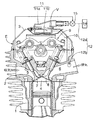
図1は参考例に係るリード弁を装着した内燃機関の縦断面図、図2は上記リード弁の拡大縦断面図、図3は同リード弁の一部破断正面図(図2の3矢視図)、図4は同リード弁の裏面図(図2の4矢視図)、図5は本発明の実施例に係るリード弁の一部破断正面図、図6は同リード弁の裏面図である。
【0015】
先ず、図1〜図4に示す参考例の説明から始める。
【0016】
図1において、参照符号Eは自動二輪車用の内燃機関を示す。この内燃機関Eは、下方から順次接合されるシリンダブロック1、シリンダヘッド2及びヘッドカバー3を備える。シリンダヘッド2には、燃焼室4と、この燃焼室4にそれぞれ開口する吸気ポート5及び排気ポート6とが形成されると共に、これら吸、排気ポート5、6を開閉す吸気弁7及び排気弁8と、これら吸、排気弁7、8を開閉駆動する動弁機構9とが設けられる。この動弁機構9は、シリンダヘッド2とヘッドカバー3との間に画成される動弁室10に配設される。吸気ポート5の上流側には気化器が取り付けられ、排気ポート6の下流側には、排気管を介してマフラ(何れも図示せず)が接続される。
【0017】
またヘッドカバー3には、本発明のリード弁Vを取り付ける弁ハウジング11が設けられる。この弁ハウジング11は、ヘッドカバー3に一体に成形される下部ハウジング半体11bと、ヘッドカバー3の上面にねじ止めされる上部ハウジング半体11aとで構成され、リード弁Vは、その上部ハウジング半体11aに装着されると共に、下部ハウジング半体11bによって下面を押さえられる。このリード弁Vは、上部ハウジング半体11a側から下部ハウジング半体11b側への一方向のみの気体の流れを許容する。
【0018】
上部ハウジング半体11aには、2次上流通路12aを介してエアクリーナ14が接続され、その2次上流通路12aの途中には、規定値以上の吸気負圧を検知して開弁する制御弁15が介装される。また下部ハウジング半体11bは、2次下流通路12bを介して排気ポート6に接続される。上記2次上流及び下流通路12a,12bは、エアクリーナ14で濾過された空気を排気ポート6に誘導する2次空気通路12を構成するものであり、したがって、この2次空気通路12の途中にはリード弁V及び制御弁15が直列に介裝されることになる。
【0019】
さて、図2〜図4により上記リード弁Vの構成について説明する。
【0020】
リード弁Vは、弁座部材20、リード24及びストッパ板25を構成要素とする。
【0021】
弁座部材20は略長方形で板状をなしており、その長手方向一端部のリード取り付け部20aから長手方向に離れて、弁座部材20の両側面を貫通する弁孔21が設けられる。この弁孔21も長手方向を弁座部材20と同じくする略長方形をなしており、この弁孔21の周囲を囲繞する、ゴム等の弾性材製の弁座22が弁座部材20の一方の側面に接着される。また弁座部材20の周囲には、ゴム等の弾性材製のシール部材23が嵌め込まれる。
【0022】
リード24は極薄の弾性金属板からなっていて、弁孔21を覆って弁座22に着座するように配設される。このリード24も長手方向を弁座部材20と同じくする略長方形をなしており、その長手方向一端部(基端部)がストッパ板25の一端部と共に弁座部材20のリード取り付け部20aに一対のビス26,26で固着され、その他端は自由端とされる。このリード24の弁座22との重なり代Sは、前記弁孔21の閉鎖に必要な最小限度の値に設定される。そして、このリード24の弁孔21への入り込みを阻止すべく、弁孔21の長辺側の両内側面に一対の突起27,27が形成される。その際、これら突起27,27は次式が成立するように配置される。
【0023】
弁孔21の長辺長さをLとしたとき、弁孔21のリード24基端側の端縁から前記突起27までの距離L′は、
L′≒0.75L
とされる。即ち、突起27,27は、弁孔21のリード24基端側の端縁から測って、弁孔21の長辺長さLの約75%の箇所に配置される。
【0024】
ストッパ板25は、リード24の、弁座22から離座する開弁時、その背面を受け止めてリード24の最大撓みを規制するもので、弁座部材20のリード取り付け部20aに固着された一端部から他端に向かってリード24から離れるように湾曲している。
【0025】
このような構成のリード弁Vは、図1に示すように、リード24及びストッパ板25を下部ハウジング半体11bに向けて、弁座部材20が上部ハウジング半体11aに嵌装される。その際、シール部材23が上部ハウジング半体11aの内周面に密接して、弁座部材20と上部ハウジング半体11aとの嵌合部の気密を保つ。
【0026】
次に、この参考例の作用について説明する。
【0027】
内燃機関Eの減速運転時、吸入負圧が一定値以上になると、それを検知した制御弁15は開弁して、2次上流通路12aを導通状態にする。そこで、排気ポート6及びそれに接続された排気管を含む排気系に圧力の脈動が発生すると、その脈動は、2次下流通路12bを経て下部ハウジング半体11b内に到達して、リード弁Vのリード24を開閉方向に振動させる。即ち、下部ハウジング半体11b内に負圧が到来したときは、リード24は弁座22から離座して弁孔21を開くので、その負圧は2次上流通路12aへと伝達し、その結果、エアクリーナ14で濾過された外気が2次空気通路12及び弁孔21を経て排気ポート6に吸入され、また下部ハウジング半体11b内に正圧が到来したときは、リード24は弁座22に着座して弁孔21を閉鎖するので、2次空気通路12での空気の逆流が阻止される。このような排気系の圧力脈動とリード弁Vの作動により、2次空気通路12を通して排気ポート6に間欠的に2次空気が導入されるから、減速運転に伴う排ガス中の未燃成分濃度の増加があっても、その未燃成分を排気系内で燃焼、浄化することができる。
【0028】
尚、内燃機関Eの通常運転時にも、下部ハウジング半体11bには排気系の圧力脈動が作用するので、リード弁Vのリード24は開閉振動するが、この通常運転時には吸気負圧が比較的低く、制御弁15が閉弁して2次上流通路12aを遮断しているから、排気ポート6への2次空気の供給は行われない。
【0029】
ところで、リード24周りの気体の流れ状態によっては、リード24に長手方向軸線周りの捩じれ変形が発生することがあるが、そのような場合でも、弁孔21の長辺側の両内側面に一対の突起27,27が形成されているから、これら突起27,27がリード24の長辺側の両側縁部を受け止めて、その捩じれを抑制して弁孔21への入り込みを阻止し、リード24の弁座22への正常な着座へと導くことができる。
【0030】
テストによれば、リード24の捩れは、弁孔21の長手方向中央部で最も大きいが、リード24のリード取り付け部20aに対する取り付け誤差により、リード24が傾いて取り付けられることも考慮すると、弁孔21がリード24と長手方向を同じくする略長方形である場合は、弁孔21の突起27,27を、前述のように、弁孔21のリード24基端側の端縁から測って、弁孔21の長辺長さLの約75%の箇所に配置するときが、突起27,27の、リード24の捩じれに対する抑制効果が最も高いことを確認しており、したがって突起27,27の突出長さを極力小さくしつゝリード24の捩じれを効果的に抑え、リード24の弁孔21への入り込みを確実に防ぐことができる。
【0031】
かくして、リード24の弁座との重なり代を弁孔21の閉鎖のための必要最小限度の値に設定することが可能となり、リードのばね定数の増加を回避し、圧力脈動に対するリードの応答性を良好にすることができ、また気体の所望流量を確保しながらリード弁Vの小型化を図ることができる。
【0032】
そして、このようなリード弁Vを、上記のように内燃機関Eの排気系への2次空気供給に使用すれば、リード24が常に排気圧力の脈動に的確に応答して排気系に2次空気を確実に供給することができ、排気浄化に寄与し得る。
【0033】
次に、図5及び図6に示す本発明の実施例について説明する。
【0034】
この実施例は、前参考例における弁孔21の突起27,27に代えて、リード24の長辺側の両側縁に一対の突起37,37を形成したものである。そして、図5,図6に示されるように、リード24の長手方向に沿う両側縁と弁座22との重なり代Sは、突起37が形成される領域を除いて弁孔21の長手方向全域に亘って一定であると共に、その突起37が形成される領域では該突起37が形成されない領域よりも大である。その他の構成は前参考例と同様であるから、図5及び図6中、前参考例との対応部分には同一の参照符号を付して、その説明を省略する。
【0035】
この実施例においても、リード24が長手方向軸線周りに捩じれながら弁孔21に入り込もうとしても、リード24の両側縁の突起37,37が弁孔21両側縁の弁座22に受け止められることによりリード24の捩じれが抑制され、弁孔21への入り込みが防止され、したがってリード24は弁座22への正常な着座へと導かれる。したがって、この場合もリード24の弁座との重なり代を弁孔21の閉鎖のための必要最小限度の値に設定することが可能であり、リードのばね定数の増加を回避し、圧力脈動に対するリードの応答性を良好にすることができ、また特に前記突起37,37による弁孔21の開口面積の減少もなく、気体の所望流量を確保しながらリード弁Vの小型化を図ることができる。
【0036】
またこのリード弁Vを、前記参考例のように内燃機関Eの排気系への2次空気供給に使用すれば、リード24が常に排気圧力の脈動に的確に追従して排気系に2次空気を確実に供給し、排気浄化に寄与し得ることは勿論である。
【0037】
本発明は、上記実施例に限定されるものではなく、その要旨の範囲を逸脱することなく種々の設計変更が可能である。
【0038】
【発明の効果】
以上のように本発明の第1の特徴によれば、長方形の弁孔を有する弁座部材と、その弁座部材に長手方向一端部を固着されて弁孔を覆うリードとを備えていて、リードが弁孔と長手方向を同じくする長方形に形成されるリード弁において、リードの長手方向に沿う両側縁に、弁孔の長手方向に沿う両側縁の弁座にそれぞれ受け止められてリードの弁孔への入り込みを阻止する一対の突起を、弁孔の長手方向中央部よりもリードの自由端寄りの位置でそれぞれ形成し、リードの長手方向に沿う両側縁と弁座との重なり代は、突起が形成される領域を除いて弁孔の長手方向全域に亘って一定であると共に、前記突起が形成される領域では前記突起が形成されない領域よりも大であるので、リード周りの気体の流れ状態によってリードが長手方向軸線周りに捩じれながら弁孔に入り込もうとしても、リード両側縁の、リード自由端寄りの突起が弁孔両側縁の弁座にそれぞれ受け止められてその捩じれが抑制され、リードの弁孔への入り込みを阻止することができる。その結果、リードの弁座との重なり代を弁孔の閉鎖のための必要最小限度の値に設定することが可能となり、リードのばね定数の増加を回避し、圧力脈動に対するリードの応答性を良好にすることができ、また特に前記突起による弁孔の開口面積の減少もなく、気体の所望流量を確保しながらリード弁の小型化を図ることができる。
【0039】
さらに本発明の第2の特徴によれば、弁孔を、その長手方向をリードと同じくする長方形に形成し、この弁孔のリード長手方向一端側の端縁から前記突起までの距離を、弁孔の長辺長さの75%と設定したので、突起の突出長さを極力小さくしつゝリードの捩じれを効果的に抑え、弁孔への入り込みを確実に防ぐことができる。
【0040】
さらにまた本発明の第3の特徴によれば、内燃機関の排気系に接続される2次空気通路に、リードを該通路の下流側に向けてリード弁を介装したので、リードが常に排気系の圧力脈動に的確に応答して振動し、排気系に2次空気を確実に供給して排気浄化に寄与し得る。
【図面の簡単な説明】
【図1】 参考例に係るリード弁を装着した内燃機関の縦断面図。
【図2】 上記リード弁の拡大縦断面図。
【図3】 同リード弁の一部破断正面図(図2の3矢視図)。
【図4】 同リード弁の裏面図(図2の4矢視図)。
【図5】 本発明の実施例に係るリード弁の一部破断正面図。
【図6】 同リード弁の裏面図。
【符号の説明】
6・・・・・・吸気系(吸気ポート)
12・・・・・2次空気通路
20・・・・・弁座部材
21・・・・・弁孔
22・・・・・弁座
24・・・・・リード
37・・・・・リード側縁の突起
E・・・・・・内燃機関
L・・・・・・弁孔の長辺長さ
L′・・・・・弁孔のリード基端側の端縁から突起までの距離
V・・・・・・リード弁[0001]
BACKGROUND OF THE INVENTION
The present invention relates to a valve seat having a valve seat and a valve hole opening to the valve seat, and a valve hole having a longitudinal end fixed to the valve seat member in order to open and close the valve hole in cooperation with the valve seat. The present invention relates to an improvement of a reed valve having a reed covering the same.
[0002]
[Prior art]
Such a reed valve is already known, for example, as disclosed in Japanese Patent Publication No. 60-32339.
[0003]
[Problems to be solved by the invention]
Such a reed valve is generally widely used to transfer gas in one direction by opening and closing the valve hole by flexing and vibrating the reed by the surrounding pressure pulsation. Depending on the condition, the lead may be twisted and deformed around its longitudinal axis and enter the valve hole.
[0004]
Conventionally, in order to prevent such a situation, the allowance for overlapping with the valve seat of the reed is made sufficiently large, but the allowance for overlap with the valve seat of the reed is used to close the valve hole. Setting the size larger than the required size will lead to a decrease in the responsiveness of the lead to pressure pulsation due to an increase in the spring constant of the lead, or a decrease in the opening area of the valve hole. This causes a disadvantage that the transfer flow rate is reduced. Therefore, in order to compensate for the decrease in the gas transfer flow rate, the reed valve itself has been forced to increase in size.
[0005]
The present invention has been made in view of such circumstances, and the responsiveness to the pressure pulsation of the lead is set by setting the overlap margin with the valve seat of the lead to a minimum necessary value for closing the valve hole. Another object of the present invention is to provide a reed valve that can prevent the reed from entering the valve hole while ensuring a predetermined opening area of the valve hole.
[0006]
[Means for Solving the Problems]
To achieve the above object, the present invention includes a valve seat member having a valve hole of the rectangle that is open to the valve seat and the valve seat, to open and close the valve hole in cooperation with the valve seat, the valve seat member one longitudinal end portion is fixed to have a lead over the valve hole, a reed valve which leads are formed similarly rectangle the valve hole and longitudinally opposite side edges along the longitudinal direction of the lead In addition, a pair of protrusions that are received by the valve seats on both side edges along the longitudinal direction of the valve hole and prevent the lead from entering the valve hole are positioned closer to the free end of the lead than the longitudinal center part of the valve hole. in forming each overlapping margin between the side edges and the valve seat along the longitudinal direction of the lead, along with projections is one Jode 4 throughout the entire length of the valve hole except for regions to be formed, said projection is formed the that in a region that is is larger than the projection is not formed region It is a feature of the.
[0007]
According to the first feature, even if the lead tries to enter the valve hole while being twisted around the longitudinal axis due to the state of gas flow around the lead, the protrusions on both side edges of the lead are received by the valve seats on both side edges of the valve hole. Therefore, the twist is suppressed, and the lead can be prevented from entering the valve hole. As a result, it is possible to set the margin of overlap with the valve seat of the lead to the minimum value necessary for closing the valve hole, avoiding an increase in the spring constant of the lead, and improving the response of the lead to pressure pulsation. The reed valve can be reduced in size while ensuring a desired flow rate of gas without particularly reducing the opening area of the valve hole due to the protrusion.
[0008]
The present invention, in addition to the first feature, the distance from the lead longitudinal end edge of the valve hole to the projection, that was set at 75% of the long side of the valve hole second It is characterized by.
[0009]
According to the second feature, the suppression effect of the protrusion on the twisting of the lead becomes remarkable, and the twisting of the lead can be effectively prevented while reducing the protrusion length of the protrusion as much as possible.
[0010]
Furthermore, in the present invention, in addition to the first or second feature, a reed valve is interposed in the secondary air passage connected to the exhaust system of the internal combustion engine so that the lead faces the downstream side of the passage. The third feature.
[0011]
The exhaust system corresponds to the
[0012]
According to the third feature, the lead always vibrates in response to the pressure pulsation of the exhaust system accurately, and the secondary air can be reliably supplied to the exhaust system to contribute to exhaust purification.
[0013]
DETAILED DESCRIPTION OF THE INVENTION
Embodiments of the present invention will be described based on a reference example shown in the accompanying drawings and an embodiment of the present invention.
[0014]
1 is a longitudinal sectional view of an internal combustion engine equipped with a reed valve according to a reference example, FIG. 2 is an enlarged longitudinal sectional view of the reed valve, and FIG. 3 is a partially broken front view of the reed valve (see
[0015]
First, the description of the reference example shown in FIGS.
[0016]
In FIG. 1, reference numeral E indicates an internal combustion engine for a motorcycle. The internal combustion engine E includes a cylinder block 1, a
[0017]
The
[0018]
An
[0019]
Now, the configuration of the reed valve V will be described with reference to FIGS.
[0020]
The reed valve V includes a
[0021]
The
[0022]
The
[0023]
When the long side length of the
L '≒ 0.75L
It is said. That is, the
[0024]
The
[0025]
As shown in FIG. 1, in the reed valve V having such a configuration, the
[0026]
Next, the operation of this reference example will be described.
[0027]
When the internal combustion engine E is decelerated, if the suction negative pressure becomes a certain value or more, the
[0028]
Even during normal operation of the internal combustion engine E, the pressure pulsation of the exhaust system acts on the
[0029]
By the way, depending on the flow state of the gas around the
[0030]
According to the test, the torsion of the
[0031]
Thus, it is possible to set the overlap margin between the lead 24 and the valve seat to a minimum value necessary for closing the
[0032]
If such a reed valve V is used for supplying secondary air to the exhaust system of the internal combustion engine E as described above, the
[0033]
Next, the embodiment of the present invention shown in FIGS. 5 and 6 will be described.
[0034]
This embodiment, before instead of the
[0035]
Also in this embodiment, even if the
[0036]
If this reed valve V is used for supplying secondary air to the exhaust system of the internal combustion engine E as in the above-mentioned reference example, the
[0037]
The present invention is not limited to the above embodiments, and various design changes can be made without departing from the scope of the gist of the present invention.
[0038]
【The invention's effect】
According to a first aspect of the present invention as described above, comprise a valve seat member having a valve hole of the rectangle, and lead covering the valve hole is secured to one longitudinal end to the valve seat member in reed valve leads are formed on the rectangle, with the same valve hole and longitudinally on both side edges along the longitudinal direction of the lead, they are received respectively on the valve seat of both side edges along the longitudinal direction of the valve hole of the lead A pair of protrusions that prevent entry into the valve hole are formed at positions closer to the free end of the lead than the central part in the longitudinal direction of the valve hole, and the overlap margin between the side edges along the longitudinal direction of the lead and the valve seat is , together with the projections except for the region to be formed is one Jode 4 throughout the entire length of the valve hole, since the in the region where projections are formed is a larger than the projection is not formed region, the gas around the lead Depending on the flow state of the lead, the longitudinal axis Even if it tries to enter the valve hole while being twisted around, the protrusions on both side edges of the lead near the free end of the lead are received by the valve seats on both side edges of the valve hole, respectively, and the twist is suppressed, so that the lead enters the valve hole. Can be blocked. As a result, it is possible to set the margin of overlap with the valve seat of the lead to the minimum value necessary for closing the valve hole, avoiding an increase in the spring constant of the lead, and improving the response of the lead to pressure pulsation. The reed valve can be reduced in size while ensuring a desired flow rate of gas without particularly reducing the opening area of the valve hole due to the protrusion.
[0039]
Further according to the second aspect of the present invention, a valve hole, formed in a rectangle, with the same longitudinal direction and lead, the distance from the lead longitudinal end edge of the valve hole to said protrusion, having set 75% of the long side of the valve hole, the twisting of minimizing qualityゝleading projection length of the projection effectively suppressed, can be reliably prevented from entering into the valve hole.
[0040]
Further, according to the third feature of the present invention, since the reed valve is interposed in the secondary air passage connected to the exhaust system of the internal combustion engine so that the reed is directed to the downstream side of the passage, the reed is always exhausted. It can vibrate in response to the pressure pulsation of the system accurately, and can reliably supply secondary air to the exhaust system and contribute to exhaust purification.
[Brief description of the drawings]
FIG. 1 is a longitudinal sectional view of an internal combustion engine equipped with a reed valve according to a reference example.
FIG. 2 is an enlarged vertical sectional view of the reed valve.
FIG. 3 is a partially broken front view of the reed valve (as viewed in the direction of
FIG. 4 is a rear view of the reed valve (viewed in the direction of arrow 4 in FIG. 2).
FIG. 5 is a partially broken front view of a reed valve according to an embodiment of the present invention.
FIG. 6 is a rear view of the reed valve.
[Explanation of symbols]
6 .... Intake system (intake port)
12 ...
Claims (3)
リード(24)の長手方向に沿う両側縁に、弁孔(21)の長手方向に沿う両側縁の弁座(22)にそれぞれ受け止められてリード(24)の弁孔(21)への入り込みを阻止する一対の突起(37)を、弁孔(21)の長手方向中央部よりもリード(24)の自由端寄りの位置でそれぞれ形成し、
リード(24)の長手方向に沿う両側縁と弁座(22)との重なり代は、突起(37)が形成される領域を除いて弁孔(21)の長手方向全域に亘って一定であると共に、前記突起(37)が形成される領域では前記突起(37)が形成されない領域よりも大であることを特徴とする、リード弁。Closing a valve seat (22) and the valve seat member having a rectangle of the valve hole (21) which opens to the valve seat (22) (20), a valve hole (21) in cooperation with the valve seat (22) Therefore, a lead (24) having one end in the longitudinal direction fixed to the valve seat member (20) and covering the valve hole (21) is provided, and the lead (24) has the same longitudinal direction as the valve hole (21). to a reed valve which is formed in rectangle,
The lead (24) is received by the valve seats (22) on both side edges along the longitudinal direction of the valve hole (21) at both side edges along the longitudinal direction of the lead (24), and the lead (24) enters the valve hole (21). A pair of protrusions (37) for blocking are formed at positions closer to the free end of the lead (24) than the longitudinal center of the valve hole (21),
Overlapping margin between the lead side edge and the valve seat along the longitudinal direction (24) (22), at regular 4 throughout the entire length of the valve hole (21) except for a region where protrusions (37) are formed In addition, the reed valve is characterized in that the region where the protrusion (37) is formed is larger than the region where the protrusion (37) is not formed .
前記弁孔(21)のリード(24)長手方向一端側の端縁から前記突起(37)までの距離(L′)を、弁孔(21)の長辺長さ(L)の75%と設定したことを特徴とする、リード弁。The reed valve according to claim 1, wherein
The distance (L ′) from the end of the lead (24) in the longitudinal direction of the valve hole (21) to the protrusion (37) is 75% of the long side length (L) of the valve hole (21). Reed valve characterized by setting.
内燃機関(E)の排気系(6)に接続される2次空気通路(12)に、リード(24)を該通路(12)の下流側に向けて介装されることを特徴とする、リード弁。The reed valve according to claim 1 or 2,
A lead (24) is interposed in the secondary air passage (12) connected to the exhaust system (6) of the internal combustion engine (E) toward the downstream side of the passage (12), Reed valve.
Priority Applications (3)
| Application Number | Priority Date | Filing Date | Title |
|---|---|---|---|
| JP2002038301A JP4226251B2 (en) | 2002-02-15 | 2002-02-15 | Reed valve |
| KR1020030007188A KR100560827B1 (en) | 2002-02-15 | 2003-02-05 | Reed valve |
| CNB031454453A CN1289843C (en) | 2002-02-15 | 2003-02-11 | Leaf valve |
Applications Claiming Priority (1)
| Application Number | Priority Date | Filing Date | Title |
|---|---|---|---|
| JP2002038301A JP4226251B2 (en) | 2002-02-15 | 2002-02-15 | Reed valve |
Publications (3)
| Publication Number | Publication Date |
|---|---|
| JP2003240142A JP2003240142A (en) | 2003-08-27 |
| JP2003240142A5 JP2003240142A5 (en) | 2005-08-04 |
| JP4226251B2 true JP4226251B2 (en) | 2009-02-18 |
Family
ID=27779648
Family Applications (1)
| Application Number | Title | Priority Date | Filing Date |
|---|---|---|---|
| JP2002038301A Expired - Fee Related JP4226251B2 (en) | 2002-02-15 | 2002-02-15 | Reed valve |
Country Status (3)
| Country | Link |
|---|---|
| JP (1) | JP4226251B2 (en) |
| KR (1) | KR100560827B1 (en) |
| CN (1) | CN1289843C (en) |
Families Citing this family (3)
| Publication number | Priority date | Publication date | Assignee | Title |
|---|---|---|---|---|
| JP2014031775A (en) * | 2012-08-03 | 2014-02-20 | Denso Corp | Reed valve |
| CN104102237B (en) * | 2014-07-08 | 2016-09-07 | 北京七星华创电子股份有限公司 | A kind of regulation valve characteristic optimization method of mass flow controller |
| JP2017015161A (en) * | 2015-06-30 | 2017-01-19 | いすゞ自動車株式会社 | Reed valve device |
-
2002
- 2002-02-15 JP JP2002038301A patent/JP4226251B2/en not_active Expired - Fee Related
-
2003
- 2003-02-05 KR KR1020030007188A patent/KR100560827B1/en not_active Expired - Fee Related
- 2003-02-11 CN CNB031454453A patent/CN1289843C/en not_active Expired - Fee Related
Also Published As
| Publication number | Publication date |
|---|---|
| CN1289843C (en) | 2006-12-13 |
| KR20030069053A (en) | 2003-08-25 |
| JP2003240142A (en) | 2003-08-27 |
| CN1460804A (en) | 2003-12-10 |
| KR100560827B1 (en) | 2006-03-13 |
Similar Documents
| Publication | Publication Date | Title |
|---|---|---|
| JP4497936B2 (en) | Reed valve | |
| US7066296B2 (en) | Valve device for silencer | |
| JP4226251B2 (en) | Reed valve | |
| JPH10196814A (en) | Diaphragm-operated flow control valve | |
| JP6859818B2 (en) | Secondary air injection device | |
| US6701961B2 (en) | Reed valve | |
| US4476676A (en) | Secondary air supply control device for exhaust gas purifying apparatus of internal combustion engines | |
| JP2003028007A (en) | Mixer for multi-cylinder gas engine | |
| JPS6353362B2 (en) | ||
| JP4496218B2 (en) | Vaporizer | |
| JPS5856323Y2 (en) | Engine secondary air supply system | |
| JP2604414Y2 (en) | Blow-by gas reduction device | |
| TWI378200B (en) | ||
| JPH0730687B2 (en) | Valve holding structure for internal combustion engine | |
| JP4217672B2 (en) | Solenoid valve for gas control | |
| JP2003184562A (en) | Reed valve | |
| JP2905586B2 (en) | Engine intake system | |
| JPH1077914A (en) | Exhaust gas recirculation device | |
| JPH09217659A (en) | Exhaust gas recirculation device | |
| JP2004270505A (en) | Secondary air supply device | |
| JP2007009767A (en) | Secondary air supply device with intake control function | |
| JPH11182361A (en) | Canister abnormal noise prevention structure | |
| JP3820196B2 (en) | Reed valve | |
| JPH0663809U (en) | Blow-by gas reduction device | |
| JPS62147014A (en) | Intake valve deactivation mechanism Intake device for engine |
Legal Events
| Date | Code | Title | Description |
|---|---|---|---|
| A521 | Request for written amendment filed |
Free format text: JAPANESE INTERMEDIATE CODE: A523 Effective date: 20050106 |
|
| A621 | Written request for application examination |
Free format text: JAPANESE INTERMEDIATE CODE: A621 Effective date: 20050114 |
|
| A977 | Report on retrieval |
Free format text: JAPANESE INTERMEDIATE CODE: A971007 Effective date: 20070112 |
|
| A131 | Notification of reasons for refusal |
Free format text: JAPANESE INTERMEDIATE CODE: A131 Effective date: 20070117 |
|
| A521 | Request for written amendment filed |
Free format text: JAPANESE INTERMEDIATE CODE: A523 Effective date: 20070319 |
|
| A131 | Notification of reasons for refusal |
Free format text: JAPANESE INTERMEDIATE CODE: A131 Effective date: 20070808 |
|
| A521 | Request for written amendment filed |
Free format text: JAPANESE INTERMEDIATE CODE: A523 Effective date: 20071009 |
|
| A131 | Notification of reasons for refusal |
Free format text: JAPANESE INTERMEDIATE CODE: A131 Effective date: 20080312 |
|
| A521 | Request for written amendment filed |
Free format text: JAPANESE INTERMEDIATE CODE: A523 Effective date: 20080512 |
|
| A131 | Notification of reasons for refusal |
Free format text: JAPANESE INTERMEDIATE CODE: A131 Effective date: 20081001 |
|
| A521 | Request for written amendment filed |
Free format text: JAPANESE INTERMEDIATE CODE: A523 Effective date: 20081014 |
|
| TRDD | Decision of grant or rejection written | ||
| A01 | Written decision to grant a patent or to grant a registration (utility model) |
Free format text: JAPANESE INTERMEDIATE CODE: A01 Effective date: 20081112 |
|
| A01 | Written decision to grant a patent or to grant a registration (utility model) |
Free format text: JAPANESE INTERMEDIATE CODE: A01 |
|
| A61 | First payment of annual fees (during grant procedure) |
Free format text: JAPANESE INTERMEDIATE CODE: A61 Effective date: 20081126 |
|
| FPAY | Renewal fee payment (event date is renewal date of database) |
Free format text: PAYMENT UNTIL: 20111205 Year of fee payment: 3 |
|
| R150 | Certificate of patent or registration of utility model |
Free format text: JAPANESE INTERMEDIATE CODE: R150 |
|
| FPAY | Renewal fee payment (event date is renewal date of database) |
Free format text: PAYMENT UNTIL: 20111205 Year of fee payment: 3 |
|
| FPAY | Renewal fee payment (event date is renewal date of database) |
Free format text: PAYMENT UNTIL: 20121205 Year of fee payment: 4 |
|
| FPAY | Renewal fee payment (event date is renewal date of database) |
Free format text: PAYMENT UNTIL: 20121205 Year of fee payment: 4 |
|
| FPAY | Renewal fee payment (event date is renewal date of database) |
Free format text: PAYMENT UNTIL: 20131205 Year of fee payment: 5 |
|
| LAPS | Cancellation because of no payment of annual fees |