JP4230367B2 - 利得可変増幅器、キャリア検出回路システム、及びそれらを用いた赤外線リモコン受信機 - Google Patents
利得可変増幅器、キャリア検出回路システム、及びそれらを用いた赤外線リモコン受信機 Download PDFInfo
- Publication number
- JP4230367B2 JP4230367B2 JP2004006011A JP2004006011A JP4230367B2 JP 4230367 B2 JP4230367 B2 JP 4230367B2 JP 2004006011 A JP2004006011 A JP 2004006011A JP 2004006011 A JP2004006011 A JP 2004006011A JP 4230367 B2 JP4230367 B2 JP 4230367B2
- Authority
- JP
- Japan
- Prior art keywords
- amplifier
- current
- detection circuit
- carrier detection
- circuit
- Prior art date
- Legal status (The legal status is an assumption and is not a legal conclusion. Google has not performed a legal analysis and makes no representation as to the accuracy of the status listed.)
- Expired - Fee Related
Links
Images


Classifications
-
- H—ELECTRICITY
- H03—ELECTRONIC CIRCUITRY
- H03G—CONTROL OF AMPLIFICATION
- H03G3/00—Gain control in amplifiers or frequency changers
- H03G3/20—Automatic control
- H03G3/30—Automatic control in amplifiers having semiconductor devices
- H03G3/3084—Automatic control in amplifiers having semiconductor devices in receivers or transmitters for electromagnetic waves other than radiowaves, e.g. lightwaves
-
- G—PHYSICS
- G08—SIGNALLING
- G08C—TRANSMISSION SYSTEMS FOR MEASURED VALUES, CONTROL OR SIMILAR SIGNALS
- G08C23/00—Non-electrical signal transmission systems, e.g. optical systems
- G08C23/04—Non-electrical signal transmission systems, e.g. optical systems using light waves, e.g. infrared
Landscapes
- Physics & Mathematics (AREA)
- General Physics & Mathematics (AREA)
- Electromagnetism (AREA)
- Control Of Amplification And Gain Control (AREA)
- Digital Transmission Methods That Use Modulated Carrier Waves (AREA)
- Circuits Of Receivers In General (AREA)
Description
Vo1=Vcc−R*(1/2)*I1−R*gm/2*(Vin1−Vin2)
=Vcc−R*(1/2)*I1−R*I1/(4Vt)*(Vin1−Vin2) ・・・・・(1)
Vo2=Vcc−R*(1/2)*I1+R*gm/2*(Vin1−Vin2)
=Vcc−R*(1/2)*I1+R*I1/(4Vt)*(Vin1−Vin2) ・・・・・(2)
gm=(I1/2)/Vt ・・・・・(3)
(ここで、Vt=kT/q、k:ボルツマン定数、T:絶対温度、q:電子の素電荷)
よって、差動電圧利得Avは、
Av=(Vo1−Vo2)/(Vin1−Vin2)
=−R*I1/(2Vt) ・・・・・(4)
となる。
Vo1=Vcc−R*(1/2)*(I1−Iagc)−R*(I1−Iagc)
/(4Vt)*(Vin1−Vin2) ・・・・・(5)
Vo2=Vcc−R*(1/2)*(I1−Iagc)+R*(I1−Iagc)/
/(4Vt)*(Vin1−Vin2) ・・・・・(6)
Av=−R*(I1−Iagc)/(2Vt) ・・・・・(7)
となる。
このとき、充放電電流値を小さくすると、充放電回路のトランジスタのインピーダンスが上がり、ノイズの影響が大きくなるといった問題がある。
出力抵抗ro=Va/Ic ・・・・・(10)
(Vt=k*T/q、k:ボルツマン定数、T:絶対温度、q:電子の素電荷)
(Va=アーリ電圧)
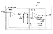
したがって、コスト削減のためにコンデンサC内蔵キャリア検出回路を用いるのが一般的ではあるが、その場合、キャリア検出回路出力Detに重畳したノイズは大きくなり、利得可変増幅器−キャリア検出回路システムに影響を及ぼす。
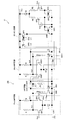
積分回路6、及びヒステリシスコンパレータ7等を有している。上記アンプ1・2・3、バンドパスフィルタ(BPF)4、キャリア検出回路5、積分回路6、及びヒステリシスコンパレータ7等は、集積化された受信チップからなっている。
Vo1=Vcc−R*(1/2)*I1−R*gm/2*(Vin1−Vin2)
=Vcc−R*(1/2)*I1−R*I1/(4Vt)*(Vin1−Vin2) ・・・・・(11)
Vo2=Vcc−R*(1/2)*I1+R*gm/2*(Vin1−Vin2)
=Vcc−R*(1/2)*I1+R*I1/(4Vt)*(Vin1−Vin2) ・・・・・(12)
gm=(I1/2)/Vt ・・・・・(13)
(ここで、Vt=kT/qk:ボルツマン定数、T:絶対温度、q:電子の素電荷)
よって、差動電圧利得Avは、
Av=(Vo1−Vo2)/(Vin1−Vin2)
=−R*I1/(2Vt) ・・・・(14)
となる。
Vo1=Vcc−R*(1/2)*(I1−Iagc)+R*(1/2)*(Iagc)
−R*(I1−Iagc)/(4Vt)*(Vin1−Vin2)
=Vcc−R*(1/2)*(I1)−R*(I1−Iagc)/(4Vt)*
(Vin1−Vin2) ・・・・・(15)
Vo2=Vcc−R*(1/2)*(I1−Iagc)+R*(1/2)*(Iagc)
+R*(I1−Iagc)/(4Vt)*(Vin1−Vin2)
=Vcc−R*(1/2)*(I1)+R*(I1−Iagc)/(4Vt)*
(Vin1−Vin2) ・・・・・(16)
よって、差動電圧利得Avは、
Av=(Vo1−Vo2)/(Vin1−Vin2)
=−R*(I1−Iagc)/(2Vt) ・・・・(17)
となる。
これを、式で示すと、以下のようになる。
ここで、gm=1/(2*RE+4Vt/I2)
(ただし、gm:トランスコンダクタンス、Vt=kT/q、k:ボルツマン定数、 T:絶対温度、q:電子の素電荷である。)
この結果、電圧(Vdet)に応じて次式の電流が出力され、オートゲインコントロールを行う。
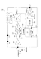
次に、上述の説明では、AMP回路部20とAGC回路30とからなる利得可変増幅回路11としての説明を行ったが、これに対して、図3に示すように、この利得可変増幅回路11にキャリア検出回路5を加えてキャリア検出回路システム40として構成することが可能である。
2a アンプ
2b アンプ
4 バンドパスフィルタ〔BPF〕(フィルタ回路)
5 キャリア検出回路
10 赤外線リモコン受信機
11 利得可変増幅回路(利得可変増幅器)
12 利得可変増幅回路(利得可変増幅器)
15 赤外線リモコン受信機
20 AMP回路部
20a AMP回路
20b AMP回路
30 AGC回路
40 キャリア検出回路システム
50 キャリア検出回路システム
Vo1 AMP回路部の出力電圧
Vo2 AMP回路部の出力電圧
I1−Iagc AMP回路部のバイアス電流
Claims (5)
- 制御電圧により、電流源にゲイン調整用電流を供給して、アンプのバイアス電流を低減する利得可変増幅器において、
上記アンプの正及び負の各出力から、ゲイン調整用電流の1/2からなる電流を引き抜く電流引き抜き手段が設けられていること特徴とする利得可変増幅器。 - アンプ回路、フィルタ回路、キャリア検出回路、及び請求項1記載の利得可変増幅器を含み、上記キャリア検出回路の出力レベルを検出し、上記利得可変増幅器を介して上記アンプ回路のゲイン調整を行うことを特徴とするキャリア検出回路システム。
- 前記アンプ回路は、ゲイン調整を行うための第1段目アンプ及び第2段目アンプの2段のアンプを直列に備えていると共に、
前記電流引き抜き手段は、第1段目アンプの正及び負の各出力から、ゲイン調整用電流の1/2からなる電流を引き抜き、その出力を第2段目アンプに入力し、第2段目アンプの正及び負の各出力から、ゲイン調整用電流の1/2からなる電流を引き抜くことを特徴とする請求項2記載のキャリア検出回路システム。 - 請求項1記載の利得可変増幅器を用いたことを特徴とする赤外線リモコン受信機。
- 請求項2又は3記載のキャリア検出回路システムを用いたことを特徴とする赤外線リモコン受信機。
Priority Applications (3)
| Application Number | Priority Date | Filing Date | Title |
|---|---|---|---|
| JP2004006011A JP4230367B2 (ja) | 2004-01-13 | 2004-01-13 | 利得可変増幅器、キャリア検出回路システム、及びそれらを用いた赤外線リモコン受信機 |
| US11/034,181 US20050152705A1 (en) | 2004-01-13 | 2005-01-12 | Gain variable amplifier, carrier detection system, and infrared remote-control receiver using them |
| CNA2005100044091A CN1642002A (zh) | 2004-01-13 | 2005-01-13 | 可变增益放大器、载波检测系统、及红外线遥控接收机 |
Applications Claiming Priority (1)
| Application Number | Priority Date | Filing Date | Title |
|---|---|---|---|
| JP2004006011A JP4230367B2 (ja) | 2004-01-13 | 2004-01-13 | 利得可変増幅器、キャリア検出回路システム、及びそれらを用いた赤外線リモコン受信機 |
Publications (2)
| Publication Number | Publication Date |
|---|---|
| JP2005203894A JP2005203894A (ja) | 2005-07-28 |
| JP4230367B2 true JP4230367B2 (ja) | 2009-02-25 |
Family
ID=34737254
Family Applications (1)
| Application Number | Title | Priority Date | Filing Date |
|---|---|---|---|
| JP2004006011A Expired - Fee Related JP4230367B2 (ja) | 2004-01-13 | 2004-01-13 | 利得可変増幅器、キャリア検出回路システム、及びそれらを用いた赤外線リモコン受信機 |
Country Status (3)
| Country | Link |
|---|---|
| US (1) | US20050152705A1 (ja) |
| JP (1) | JP4230367B2 (ja) |
| CN (1) | CN1642002A (ja) |
Families Citing this family (10)
| Publication number | Priority date | Publication date | Assignee | Title |
|---|---|---|---|---|
| CA2626547A1 (en) * | 2005-10-21 | 2007-05-03 | Medical College Of Georgia Research Institute, Inc. | The induction of indoleamine 2,3-dioxygenase in dendritic cells by tlr ligands and uses thereof |
| US7570109B2 (en) * | 2005-11-04 | 2009-08-04 | Lite-On Technology Corp. | System and method for demodulating amplitude modulated signals |
| JP4267664B2 (ja) * | 2007-01-16 | 2009-05-27 | シャープ株式会社 | 基準電流源回路および赤外線信号処理回路 |
| US7834692B2 (en) * | 2007-09-17 | 2010-11-16 | Finisar Corporation | Peak detector with active ripple suppression |
| KR101044056B1 (ko) * | 2009-04-10 | 2011-06-27 | 주식회사 에이디텍 | 모드변환방식의 이득조절부를 구비한 적외선 수신기 |
| CN102546002B (zh) * | 2010-12-14 | 2014-09-24 | 无锡华润矽科微电子有限公司 | 红外接收电路 |
| CN102509443B (zh) * | 2011-10-20 | 2013-05-01 | 黄宇嵩 | 红外线遥控信号转发器 |
| CN103049993B (zh) * | 2013-02-07 | 2014-04-30 | 衢州昀睿工业设计有限公司 | 一种具有发射反馈信息的无线遥控接收机 |
| CN106483576B (zh) * | 2015-08-28 | 2020-09-04 | 青岛海尔智能技术研发有限公司 | 一种瓶状体检测方法及装置 |
| EP4394399B1 (en) * | 2022-12-30 | 2025-03-19 | Rohde & Schwarz GmbH & Co. KG | Measurement device for performing measurements with respect to a dut |
Family Cites Families (6)
| Publication number | Priority date | Publication date | Assignee | Title |
|---|---|---|---|---|
| US3214912A (en) * | 1963-12-23 | 1965-11-02 | Ford Motor Co | Hydrodynamic torque transmitting assembly |
| US4543665A (en) * | 1982-07-13 | 1985-09-24 | Plantronics, Inc. | Speakerphone with wireless infrared microphone |
| JP3517586B2 (ja) * | 1998-04-10 | 2004-04-12 | キヤノン株式会社 | モータ |
| KR100396010B1 (ko) * | 2000-08-02 | 2003-08-27 | 샤프 가부시키가이샤 | 캐리어 검출 회로 및 적외선 리모콘 수신기 |
| JP3801882B2 (ja) * | 2001-07-11 | 2006-07-26 | シャープ株式会社 | 充電回路および/または放電回路ならびにそれを用いるキャリア検出回路 |
| US7231152B2 (en) * | 2002-04-08 | 2007-06-12 | Silicon Communications Technology Co., Ltd. | Infrared remote control receiver (IRCR) having semiconductor signal processing device therein |
-
2004
- 2004-01-13 JP JP2004006011A patent/JP4230367B2/ja not_active Expired - Fee Related
-
2005
- 2005-01-12 US US11/034,181 patent/US20050152705A1/en not_active Abandoned
- 2005-01-13 CN CNA2005100044091A patent/CN1642002A/zh active Pending
Also Published As
| Publication number | Publication date |
|---|---|
| US20050152705A1 (en) | 2005-07-14 |
| CN1642002A (zh) | 2005-07-20 |
| JP2005203894A (ja) | 2005-07-28 |
Similar Documents
| Publication | Publication Date | Title |
|---|---|---|
| US5798664A (en) | Offset cancelling amplifier circuit having Miller integrator as offset detector | |
| US7231152B2 (en) | Infrared remote control receiver (IRCR) having semiconductor signal processing device therein | |
| JP4230367B2 (ja) | 利得可変増幅器、キャリア検出回路システム、及びそれらを用いた赤外線リモコン受信機 | |
| CN113109619B (zh) | 一种接收机解调器、峰值检测器及信号解调方法 | |
| KR100396010B1 (ko) | 캐리어 검출 회로 및 적외선 리모콘 수신기 | |
| JP2003318681A (ja) | 増幅回路及び光通信装置 | |
| CN100414835C (zh) | 载波检测电路及使用它的红外线通信装置 | |
| JP4011317B2 (ja) | 定電圧回路およびそれを用いる赤外線リモコン受信機 | |
| CN119165216A (zh) | 一种信号包络检测电路和芯片 | |
| JP3551642B2 (ja) | 増幅回路 | |
| US7659780B2 (en) | Gain control circuit | |
| JP5025771B2 (ja) | 可変利得増幅器の利得制御装置及びその利得制御方法 | |
| EP1801965A1 (en) | Analog multistage amplification circuit in the field of sensor | |
| US20080129378A1 (en) | Detector for automatic gain control | |
| US20060081779A1 (en) | Variable noise control for an optical transducer | |
| JP3801882B2 (ja) | 充電回路および/または放電回路ならびにそれを用いるキャリア検出回路 | |
| JP2002238087A (ja) | 受信回路チップ | |
| US7046092B2 (en) | Amplifier circuit having signal detection function | |
| JP3179838B2 (ja) | ノイズ検出回路 | |
| CN222966974U (zh) | 红外信号增益调节电路、触摸屏以及交互平板 | |
| US6765420B2 (en) | Pulse width detection circuit filtering the input signal and generating a binary signal | |
| JP4197248B2 (ja) | 赤外線受信回路および赤外線受信機器 | |
| JP2021022899A (ja) | トランスインピーダンス増幅回路 | |
| JP3207341B2 (ja) | リモートコントロール信号処理回路 | |
| KR20030081000A (ko) | Cmos 공정만을 사용하여 설계된 반도체 신호처리장치를 갖는 적외선 리모콘 수신기 |
Legal Events
| Date | Code | Title | Description |
|---|---|---|---|
| A621 | Written request for application examination |
Free format text: JAPANESE INTERMEDIATE CODE: A621 Effective date: 20060125 |
|
| A977 | Report on retrieval |
Free format text: JAPANESE INTERMEDIATE CODE: A971007 Effective date: 20080421 |
|
| A131 | Notification of reasons for refusal |
Free format text: JAPANESE INTERMEDIATE CODE: A131 Effective date: 20080507 |
|
| A521 | Written amendment |
Free format text: JAPANESE INTERMEDIATE CODE: A523 Effective date: 20080619 |
|
| RD02 | Notification of acceptance of power of attorney |
Free format text: JAPANESE INTERMEDIATE CODE: A7422 Effective date: 20080619 |
|
| TRDD | Decision of grant or rejection written | ||
| A01 | Written decision to grant a patent or to grant a registration (utility model) |
Free format text: JAPANESE INTERMEDIATE CODE: A01 Effective date: 20081202 |
|
| A01 | Written decision to grant a patent or to grant a registration (utility model) |
Free format text: JAPANESE INTERMEDIATE CODE: A01 |
|
| A61 | First payment of annual fees (during grant procedure) |
Free format text: JAPANESE INTERMEDIATE CODE: A61 Effective date: 20081203 |
|
| R150 | Certificate of patent or registration of utility model |
Free format text: JAPANESE INTERMEDIATE CODE: R150 |
|
| FPAY | Renewal fee payment (event date is renewal date of database) |
Free format text: PAYMENT UNTIL: 20111212 Year of fee payment: 3 |
|
| FPAY | Renewal fee payment (event date is renewal date of database) |
Free format text: PAYMENT UNTIL: 20111212 Year of fee payment: 3 |
|
| FPAY | Renewal fee payment (event date is renewal date of database) |
Free format text: PAYMENT UNTIL: 20121212 Year of fee payment: 4 |
|
| FPAY | Renewal fee payment (event date is renewal date of database) |
Free format text: PAYMENT UNTIL: 20121212 Year of fee payment: 4 |
|
| LAPS | Cancellation because of no payment of annual fees |