JP4232425B2 - Capping device - Google Patents
Capping device Download PDFInfo
- Publication number
- JP4232425B2 JP4232425B2 JP2002290361A JP2002290361A JP4232425B2 JP 4232425 B2 JP4232425 B2 JP 4232425B2 JP 2002290361 A JP2002290361 A JP 2002290361A JP 2002290361 A JP2002290361 A JP 2002290361A JP 4232425 B2 JP4232425 B2 JP 4232425B2
- Authority
- JP
- Japan
- Prior art keywords
- container
- cap
- protrusion
- capping device
- gripping
- Prior art date
- Legal status (The legal status is an assumption and is not a legal conclusion. Google has not performed a legal analysis and makes no representation as to the accuracy of the status listed.)
- Expired - Lifetime
Links
Images



Classifications
-
- B—PERFORMING OPERATIONS; TRANSPORTING
- B67—OPENING, CLOSING OR CLEANING BOTTLES, JARS OR SIMILAR CONTAINERS; LIQUID HANDLING
- B67B—APPLYING CLOSURE MEMBERS TO BOTTLES JARS, OR SIMILAR CONTAINERS; OPENING CLOSED CONTAINERS
- B67B3/00—Closing bottles, jars or similar containers by applying caps
- B67B3/20—Closing bottles, jars or similar containers by applying caps by applying and rotating preformed threaded caps
- B67B3/206—Means for preventing rotation of the container or cap
Landscapes
- Engineering & Computer Science (AREA)
- Mechanical Engineering (AREA)
- Sealing Of Jars (AREA)
Description
【0001】
【発明が属する技術分野】
本発明は、キャッピング装置に係り、特に、首部の回りにフランジが形成されている樹脂容器を、吊り下げた状態で支持している間にキャップを回転させて巻き締めを行うキャッピング装置に関するものである。
【0002】
【従来の技術】
PETボトル等の樹脂容器は、通常、首部の周囲に形成したフランジ部の下面側を支持して、吊り下げた状態で搬送している。この樹脂容器のフランジよりも上方の口部には、外周面に雄ねじが形成されており、この雄ねじに噛み合う雌ねじが形成されたキャップを前記口部に嵌合し、回転させることにより巻き締めるようになっている。キャッピング時には、容器のフランジの下側を容器保持手段によって支持した状態で、前記キャップを保持したキャッピングヘッドを回転させつつ下降させることにより、前記容器の口部に巻き締めるようになっている。
【0003】
前記キャッピングヘッドによってキャップを回転させて巻き締めを行う際に、容器がキャップとともに回転してしまうと、キャップを容器に対して設定された締め付けトルクで締結することができない。そこで、前記容器保持手段は、容器を支持するとともにキャッピング時にはその容器の回転を規制するようになっている。
【0004】
びん等の硬質容器の場合には、グリッパ等の容器保持手段によって容器の胴部をしっかりと掴んで保持することにより、キャッピング時の容器の供回りを防止することができるが、樹脂容器の場合には、胴部の肉厚が薄いためこの部分を強い力で押圧すると変形してしまい、内部に充填された液体がこぼれてしまう。そこで、容器の首部に形成されたフランジ部の下面側を支持する容器保持手段に突起を設け、この突起を容器の表面にくい込ませてキャッピング時の容器の回転を規制するようにしている。
【0005】
前述のようにキャッピング時に容器の回転を規制するために、従来は、容器を保持するスターホイールのポケットの周囲に、上向きの突起を形成し、容器に上方から荷重をかけて、その首部外周に形成されたフランジ部の下面側に前記突起をくい込ませるようにしている(特許文献2、第2頁第3欄第7行ないし第13行および第4図、第5図参照)。
【0006】
前記特許文献2に記載された従来の構成では、スターホイールのポケットの周囲に形成された上向きの突起を、容器のフランジ部の下面に確実にくい込ませるためには、キャップに対して必要以上の荷重をかけなければならず、ねじ飛びを起こすおそれがあった。
【0007】
そこで、スターホイールのポケットの内周面に突起を設けて、容器のフランジよりも下部の外周面に突き当てて容器の供回りを防止するようにしたキャッピング装置が提案されている(例えば、特許文献1および特許文献2参照)。
【0008】
【特許文献1】
特公平4−36957号公報(第3頁第5欄、第2図、第3図)
【特許文献2】
実公平8−6794号公報(第2頁第4欄、第3図)
【0009】
【発明が解決しようとする課題】
前記各特許文献に記載された構成では、スターホイールのポケットの内周面に突起を設けてあり、容器の供回りを防止できる程度にこの突起を容器の外面に押し付けるためには、スターホイールのポケットに保持されている容器の外周側を案内するために設けられている外周ガイドを、通常よりもスターホイール側に接近させて配置する必要がある。しかしながら、このように外周ガイドをスターホイールに接近させて配置して、容器をスターホイールのポケット側に押し込もうとすると、外周ガイドによって容器の首部周面に擦れ傷がついてしまうおそれがあった。
【0010】
また、縦方向の突起を容器の外周面に押し付けてこの容器の供回りを規制するためには、突起に一定以上の長さが必要であるが、特許文献2のような構成の場合には、突起の長さが長いと、フランジから遠い位置まで延びる縦長の傷が付いてしまう。このような傷が付くと、傷が目立って見た目が悪いだけでなく、この容器を購入した消費者が、開栓する際にけがをしてしまうおそれがあった。
【0011】
本発明は、前記課題を解決するためになされたもので、キャッピング時の容器の供回りを確実に規制することができ、しかも、容器に不必要な傷を付けるおそれのないキャッピング装置を提供することを目的とするものである。
【0012】
【課題を解決するための手段】
請求項1に記載した発明に係るキャッピング装置は、首部にフランジ部を有する樹脂容器を吊り下げ支持した状態でキャップを巻き締めするキャッピング装置において、一対のグリップ部材により前記フランジ部の下方を把持して前記容器を吊り下げ支持する容器把持手段を備え、前記グリップ部材の少なくともいずれか一方に、上下方向に所定の長さを有し、把持手段の把持力によって容器の首部に押し付けられる突起を設け、この突起の先端は、上端部が最も樹脂容器に接近し下方に行くに従って遠ざかる、上部から下部に向かって容器から離れるテーパ状に形成されており、この突起を、上部ほど強く下部に向かうに従って弱くなるように樹脂容器の首部周面に押し付けて把持することにより、キャップを巻き締める際の容器の供回りを防止するようにしたものである。
【0013】
この発明に係るキャッピング装置では、容器把持手段を構成する一対の開閉するグリップ部材で容器を把持するようになっており、この容器把持手段の把持力によってグリップ部材に設けられた上下方向に所定の長さを有する突起を容器に押し付けるようにしているので、従来のキャッピング装置のように固定の外周ガイドによって押し付ける場合のような摩擦がないので、容器の外面に擦り傷等ができるおそれがなく、さらに、突起の上部が容器に強く押し付けられ、下部側に行くほど容器に対して押し付けられる力が弱くなり、または、全く押し付けられない状態になるので、容器のフランジから離れた位置にはあまり傷が付かず、開栓する消費者がけがをするおそれが減少する。
【0014】
また、請求項2に記載の発明に係るキャッピング装置は、前記突起が、その先端がキャップの巻き締め方向と逆方向に向けられていることを特徴とするものである。
【0015】
この発明に係るキャッピング装置では、突起の先端がキャップの巻き締め方向と逆方向を向いているので、突起の先端がキャップの中心方向を向いている場合や、キャップの巻き締め方向と同方向を向いている場合よりも、キャッピングヘッドによる巻き締め時にキャップの表面にくい込みやすく、容器の供回りを確実に止めることができる。
【0016】
さらに、請求項3に記載の発明に係るキャッピング装置は、首部にフランジ部を有する樹脂容器を吊り下げ支持した状態でキャップを巻き締めするものであって、一対のグリップ部材により前記フランジ部の下方を把持して前記容器を吊り下げ支持する容器把持手段を備えており、さらに、前記容器把持手段は、回転体の外周部に設けられており、前記両グリップ部材は互いに向かい合って前記樹脂容器の外周に圧接される当接部を有し、各当接部は、把持している樹脂容器の中心を基準として回転体の外周側と内周側に位置するく字状の2つの面から構成され、前記グリップ部材の少なくともいずれか一方の当接部の外周側に位置している面に、上下方向に所定の長さを有し、把持手段の把持力によって容器の首部に押し付けられる突起を設け、この突起を容器の首部周面に押し付けて把持することにより、キャップを巻き締める際の容器の供回りを防止するようにしたものである。
【0017】
この発明に係るキャッピング装置では、容器把持手段を構成する一対の開閉するグリップ部材で容器を把持するようになっており、この容器把持手段の把持力によってグリップ部材に設けられた上下方向に所定の長さを有する突起を容器に押し付けるようにしているので、従来のキャッピング装置のように固定の外周ガイドによって押し付ける場合のような摩擦がないので、容器の外面に擦り傷等ができるおそれがない。
【0018】
また、請求項4に記載の発明に係るキャッピング装置は、前記容器把持手段が、回転体の回転方向の前後にグリップ部材を開閉するように構成され、回転方向後方側のグリップ部材の当接部の内周側に位置している面には突起が設けられていないことを特徴とするものである。
【0019】
回転方向後方側のグリップ部材に突起が設けられていると、両グリップ部材を開放して容器を引き渡す際に傷を付けてしまうおそれがあり、特に、回転方向後方側のグリップ部材の、容器の中心位置よりも内周側の突起が容器に傷を付けるおそれがある。しかしながら、この請求項4に記載した発明に係るキャッピング装置では、回転方向後方側のグリップ部材の内周側には突起が設けられていないので、容器を次の容器把持手段に引き渡す際に容器の外面を傷つけてしまうおそれがない。
【0024】
【発明の実施の形態】
以下、図面に示す実施の形態により本発明を説明する。図1は本発明の一実施の形態に係るキャッピング装置に設けられた容器把持手段(この実施の形態では容器把持装置と呼ぶ)の平面図、図2は前記容器把持装置によって容器を掴んだ状態を示す図である。この容器把持装置1は、一対のグリップ部材2、4を備えており、これらグリップ部材2、4間に容器6を把持する。容器把持装置1によって把持される容器6は、PETボトル等の樹脂製容器であり、上端の口部6a外周に雄ねじが形成され、その下方の首部6bにはフランジ部6cが設けられている。
【0025】
前記容器把持装置1の一対のグリップ部材2、4は、二本の直立したグリッパ軸8、10の上端にそれぞれ取付けられ、両グリッパ軸8、10が互いに逆方向に回転することにより水平面内で開閉動作する。これら両グリップ部材2、4は、揺動端(図1の左端)側に互いに向かい合う当接部12、14を有しており、閉じた状態になったときに、各当接部12、14を前記樹脂容器6のフランジ部6cの下方側(首部6b)の外周に圧接させてこの容器6を挟持するようになっている。
【0026】
これら一対のグリップ部材2、4を備えた容器把持装置1は、後に説明するように、回転体18の外周部に設けられており(図3参照)、回転体18の回転移動中に回転方向の前後に開閉して、これら両グリップ部材2、4間に導入された容器6を把持し、また、解放する。
【0027】
各グリップ部材2、4の樹脂容器6への当接部12、14は、それぞれほぼ「く」字状の2つの面12a、12b、14a、14bを有しており、これら各面12a、12b、14a、14bに、容器6の首部6bに押し付けられて容器6の回転を規制する突起16が設けられている。回転方向の前方側に位置しているグリップ部材(図1および図3の上方に位置するグリップ部材)2は、前記二つの面12a、12bのそれぞれに突起16a、16bが設けられ、一方、回転方向後方側に位置しているグリップ部材(同図の下方に位置するグリップ部材)4は、二つの面14a、14bのうちの一方14aにだけ突起16cが設けられている。
【0028】
各当接部12、14を構成するく字状の二つの面12a、12b、14a、14bは、一対のグリップ部材2、4によって保持された樹脂容器6の中心(図1中に符号O1で示す位置)を基準として、回転体18の外周側(図1の左側)と内周側(図1の右側)にそれぞれ位置しており、回転方向後方側のグリップ部材4には、二つの面14a、14bのうち容器6の中心O1よりも外周側に位置している面14aには突起16cが形成され、容器6の中心O1よりも内周側に位置している面14bには突起が設けられていない。
【0029】
前記容器把持装置1の両グリップ部材2、4に保持されて回転体18の回転方向へ移送される樹脂容器6に対し、図示しないキャッピングヘッドに保持されたキャップが巻き締められる。このキャップは、図示しないが、その内周面に、前記容器6の口部6a外周に設けられている雄ねじに噛み合う雌ねじが形成されている。キャッピングヘッドが前記キャップを保持して回転しつつ下降することにより、容器口部6aの雄ねじにキャップの雌ねじを巻き締めする。このキャッピング時のキャップの回転方向が図1の矢印R1で示す方向であり、前記各突起16a、16b、16cは、その先端が、キャップの回転方向と逆方向を向いている。つまり、図1に示すように、キャップの回転方向R1が時計回り方向の場合には、突起16a、16b、16cの先端は反時計回り方向を向いている。
【0030】
前記両グリップ部材2、4の当接面12、14に設けられている各突起16a、16b、16cは、平面形状としては、図1に示すように尖った先端部をキャップの巻き締め方向R1と逆方向に向けている。そして、上下方向では、図2に示すように、縦方向に必要な長さを有している。これら突起16a、16b、16cの先端面は、上端部が最も容器6に接近し、下方に行くに従って容器6から遠ざかるテーパ状になっている。
【0031】
これら各突起16a、16b、16cは、樹脂容器6を保持する際には、上部ほど容器6の外面に強く押し付けられ、下部に向かうに従って押し付けられる力が弱くなり、最も下部では容器6に全く接触しないか、または極めて弱い力で接する。
【0032】
突起16a、16b、16cが容器6の外面に押し付けられる部分の長さL1(図2参照)が、少なくとも2.5mm以上あると、容器6を安定して把持することができ、遠心力によるふらつきを防止することができる。ただし、この長さL1が必要以上に長すぎる場合には、容器6を安定して保持することはできるが、容器6の外面に突起16a、16b、16cを押し付けることによりできる傷が上下方向に長くなり、フランジ部6cから遠く離れた位置まで傷付いてしまう。このようにフランジ6cの下方まで延びる傷ができると、商品としての見た目が悪く、また、この容器6を購入した消費者が開栓しようとしたときに、けがをしてしまうおそれがあるので、突起16a、16b、16cを容器6の外面に押し付ける長さは2.5mm以上必要であるが、2.5mmを大幅に越えるものでないことが好ましい。なお、前記実施の形態では突起16a、16b、16cの容器6に押し付けられる部分の長さL1を2.5mm以上としているが、3mm前後とすることが望ましい。
【0033】
図4および図5は、前記容器把持装置1が設けられたキャッピング装置を示すもので、これらの図により前記一対のグリップ部材2、4を開閉する機構について説明する。中央の直立した回転軸20の上部に回転体18を構成する回転テーブル22が固定されて一体的に回転する。この回転テーブル22に、前記各グリップ部材2、4がそれぞれ取付けられているグリッパ軸8、10が回転自在に支持されている。一対のグリッパ軸8、10の一方8(以下、第1グリッパ軸と呼ぶ)の下端には、第1の歯車24がキーを介して固定され、他方のグリッパ軸10(以下、第2グリッパ軸と呼ぶ)の下部の、前記第1歯車24と同一の高さには、第2の歯車26がキーを介して固定されており、これら両歯車24、26が互いに噛合っている。
【0034】
第1グリッパ軸8の第1歯車24は、この歯車24と前記回転テーブル22の下面との間に張られたスプリング28によって、常時、図5の反時計回り方向に回転するように引かれている。従って、この第1歯車24が固定されている第1グリッパ軸8と、第1歯車24に噛合う第2歯車26が固定された第2グリッパ軸10とは、前記スプリング(第1スプリング)28によって、常に両グリップ部材2、4が開く方向に回転する力が加えられている。
【0035】
第2グリッパ軸10の下端には、第1のレバー30がキーを介して固定され、さらに、この第1レバー30と前記第2歯車26との間に第2レバー32が回転自在に嵌合している。これら第1レバー30と第2レバー32との間には、第2のスプリング34が介装され、常時、両レバー30、32を互いに反発する方向に付勢している。
【0036】
前記直立した回転軸20の下部の外周側には、固定テーブル36が配置され、ボールベアリング38によって前記回転軸20を回転自在に支持している。この固定テーブル36の上面内周寄りに、グリップ部材2、4を開閉させるグリッパカム40が形成されている。前記第2レバー32にはカムフォロア42が設けられており、このカムフォロア42を前記グリッパカム40に圧接した状態で、前記回転テーブル22が回転すると、このグリッパカム40の形状に応じてカムフォロア42が移動し第2レバー32が揺動するようになっている。
【0037】
第2レバー32のカムフォロア42をグリッパカム40に圧接させる構成を説明すると、前記第1スプリング28によって第1歯車24が図5の反時計回り方向に回転力が加えられ、この第1歯車24に噛合う第2歯車26が逆方向、すなわち図5の時計回り方向に回転力が加えられ、第2歯車26とともに第2グリッパ軸10が時計回り方向の回転力を加えられる。さらに、第2グリッパ軸10に固定された第1レバー30が同方向に回転され、この第1レバー30に対し第2スプリング34によって反発する方向に付勢されている第2レバー32が揺動してカムフォロア42をグリッパカム40に押し付けている。
【0038】
また、回転テーブル22の回転に伴なって、カムフォロア42がグリッパカム40上を移動すると、前述の説明と逆方向に力が伝達されて両グリップ部材2、4が開閉される。従って、カムフォロア42がグリッパカム40の低部領域40aを移動している間は、両グリップ部材2、4が開放し、カムフォロア42がグリッパカム40の大径領域40bに移動すると、両グリップ部材2、4が互いに接近して容器6をグリップすることができる。
【0039】
以上の構成に係るキャッピング装置に設けられた容器把持装置1の作動について説明する。グリッパカム40の低部領域40aを第2レバー32のカムフォロア42が移動している間は、カムフォロア42が内周側に位置しているので、前述のように両グリップ部材2、4が開放している。両グリップ部材2、4が開放している間に、フランジ部6cの上方を把持する容器把持手段を備えた図示しない供給ホイールから吊り下げ支持された状態で樹脂容器6が供給され、この容器6の首部6bが、開放している前記両グリップ部材2、4間に挿入される。このとき両グリップ部材2、4は、供給された容器6のフランジ部6cの僅かに下方に位置している。
【0040】
回転テーブル22の回転に伴ってカムフォロア42がグリッパカム40の大径領域40bに移動すると、両グリップ部材2、4が閉じて、当接部12、14が容器6のフランジ部6cよりも下方の首部6bに圧接される。両グリップ部材2、4の当接部12、14には突起16a、16b、16cが形成されており、これら突起16a、16b、16cの先端が容器6の首部6b外面に押し付けられて、容器6を強固に保持して吊り下げ支持する。
【0041】
グリップ部材2、4に保持されている容器6の上方には、グリップ部材2、4と一体的に移動する図示しないキャッピングヘッドが昇降、かつ回転可能に配設されており、キャップを保持して回転しつつ下降することにより、そのキャップを容器6の口部6aに被せた後巻き締めをする。樹脂容器6は両グリップ部材2、4の突起16a、16b、16cが表面に強く押し付けられた状態で保持されているので、キャップの回転に共回りすることがない。特に、突起16a、16b、16cの先端がキャップの回転される方向R1と逆方向を向いているので、キャップの回転に伴って樹脂容器6が回転しようとすると、これら突起16a、16b、16cが樹脂容器6の表面にくい込む状態になり、強力に樹脂容器6の回転を規制することができ、設定された閉栓トルクで確実に締め付けることができる。
【0042】
また、突起16a、16b、16cの先端は、上下方向にテーパ状になっているので、上部は深く樹脂容器6の表面にくい込み、下部は押し付けられていないので、樹脂容器6のフランジ部6cの下方に付けられる傷の上下方向の長さが短いため、目立つことはなく、開栓する際にけがをするおそれもない。さらに、突起16a、16b、16cの先端が上下方向にテーパ状になっているが、樹脂容器6に強く押し付けられる部分の長さL1が2.5mm以上確保されているので、上下方向に安定して樹脂容器6を保持することができ、吊り下げ支持した状態で回転体18の回転方向へ高速に移動させたときの遠心力によるふらつきを防止することができる。
【0043】
キャップを締め付けた後、容器把持装置1の両グリップ部材2、4は、第2レバー32のカムフォロア42が再びグリッパカム40の低部領域40aに移動することにより開放する。両グリップ部材2、4が開放して離された容器6は、他の回転体のネック搬送を行う容器保持手段に引き渡され(図3の左側のグリップ部材2、4参照)、またはコンベヤに引き渡される(同図の下側のグリップ部材2、4参照)。このように両グリップ部材2、4が開放して樹脂容器6を排出する際に、回転方向後方側のグリップ部材4には、回転体18の内部側に位置する面14bに突起が設けられていないので、受け渡し時に樹脂容器6の表面が突起によって傷つけられるおそれがない。
【0044】
なお、この実施の形態では、両グリップ部材2、4の各当接面12、14のうち回転方向後方側のグリップ部材4の、内周側の面14bにだけ突起を設けないようにしたが、回転方向後方側のグリップ部材4の当接面14には突起を全く設けないようにしてもよい。また、回転方向後方側のグリップ部材4の、容器6の中心O1よりも内周側の面にも突起を設けるようにしてもよい。ただし、両グリップ部材2、4の当接面12、14のそれぞれ二つの面12a、12b、14a、14bにすべて突起を設けた場合には、両グリップ部材2、4を開放して樹脂容器6を他の容器保持手段に引き渡す際に、樹脂容器6の外面を傷つけるおそれが高くなり、また、回転方向後方側のグリップ部材4には全く突起を設けない場合には、樹脂容器6を傷つけるおそれは低下するが、樹脂容器6の供回りを防止するための保持力が不足するおそれがある。従って、この実施の形態の構成が、樹脂容器6を傷つけるおそれが少なく、しかも、充分な容器保持力を得ることができるので、最も好ましい。
【0045】
また、前記実施の形態では、突起16a、16b、16cの先端の向きを、キャップの巻き締め方向R1と逆の方向に向けるようにしたが、突起16a、16b、16cの先端を樹脂容器6の中心方向O1を向けるようにした場合、あるいは、キャップの巻き締め方向R1と同方向を向けるようにした場合でも、樹脂容器6を保持してキャップの巻き締めの際に共回りしないようにすることができるが、この実施の形態のように、突起16a、16b、16cの先端をキャップの回転方向R1と逆方向に向けておけば、グリップ部材2、4の把持力を小さくしても確実に容器6の回転を阻止することができる。
【0046】
さらに、突起16a、16b、16cの先端の上下方向の形状をテーパ状にしたが、先端を鉛直方向に向けるように形成してもよい。この場合には、樹脂容器6の外面に付く傷ができるだけ短くなるように、容器6を安定して保持するために必要な2.5mmを大きく越えない長さにすることが好ましい。
【0047】
【発明の効果】
以上説明したように請求項1ないし3に記載の発明によれば、首部にフランジ部を有する樹脂容器を吊り下げ支持した状態でキャップを巻き締めするキャッピング装置において、一対のグリップ部材により前記フランジ部の下方を把持して前記容器を吊り下げ支持する容器把持手段を備え、前記グリップ部材の少なくともいずれか一方に、上下方向に所定の長さを有し、把持手段の把持力によって容器の首部に押し付けられる突起を設け、この突起を容器の首部周面に押し付けて把持することにより、キャップを巻き締める際の容器の供回りを防止するようにしたので、容器を確実に保持して、キャッピング時にキャップとともに容器が回転してしまうことを防止することができ、しかも、従来のキャッピング装置のように固定の外周ガイドによって押し付ける場合のような摩擦がないので、容器の外面に擦り傷等が出きるおそれがない。
【0048】
また、請求項1に記載の発明によれば、前記突起が、上部から下部に向かって容器から離れるテーパ状に形成されているので、突起の上部が容器に強く押し付けられ、下部側に行くほど容器に対して押し付けられる力が弱くなり、または、全く押し付けられない状態になるので、容器のフランジから離れた位置にはあまり傷が付かず、従って、傷が目立つことがなく、また、開栓する消費者がけがをするおそれが減少する。
【0049】
また、請求項2に記載の発明によれば、前記突起は、その先端がキャップの巻き締め方向と逆方向に向けられているので、キャッピングヘッドによる巻き締め時にキャップの表面にくい込みやすく、容器の供回りを確実に止めることができる。
【0050】
また、請求項4に記載の発明によれば、前記容器把持手段は、回転体の外周部に設けられ、回転体の回転方向の前後にグリップ部材を開閉するように構成され、回転方向後方側のグリップ部材の内周側には突起が設けられていないので、キャッピング後に、回転体が回転しつつグリップ部材を開放して把持していた容器を次の容器保持手段に引き渡す際に、容器の外面を傷付けてしまうおそれがない。
【図面の簡単な説明】
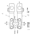
【図1】本発明の一実施の形態に係るキャッピング装置に設けられた容器把持手段の両グリップ部材を示す平面図である。
【図2】前記グリップ部材により容器を把持した状態を示す側面図である。
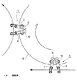
【図3】前記キャッピング装置に設けられた容器把持手段による容器の受け渡し過程を説明する平面図である。
【図4】前記キャッピング装置の要部の縦断面図である。
【図5】前記キャッピング装置に設けられたグリップ部材を開閉させる機構を示す平面図である。
【符号の説明】
1 容器把持手段
2 グリップ部材
4 グリップ部材
6 樹脂容器
6b 首部
6c フランジ部
16 突起
18 回転体[0001]
[Technical field to which the invention belongs]
The present invention relates to a capping device, and more particularly to a capping device that rotates and tightens a cap while supporting a resin container having a flange formed around a neck portion in a suspended state. is there.
[0002]
[Prior art]
A resin container such as a PET bottle is usually transported in a suspended state while supporting the lower surface side of the flange portion formed around the neck portion. A male screw is formed on the outer peripheral surface of the mouth portion above the flange of the resin container, and a cap formed with a female screw that meshes with the male screw is fitted into the mouth portion and is wound by rotating. It has become. At the time of capping, the lower side of the flange of the container is supported by the container holding means, and the capping head holding the cap is lowered while rotating to be tightened around the mouth of the container.
[0003]
When the container is rotated together with the cap when the cap is rotated by the capping head and the cap is tightened, the cap cannot be fastened with a tightening torque set with respect to the container. Therefore, the container holding means supports the container and regulates the rotation of the container during capping.
[0004]
In the case of hard containers such as bottles, it is possible to prevent the container from rotating during capping by firmly grasping and holding the body of the container with a container holding means such as a gripper. In this case, since the thickness of the body portion is thin, it is deformed when this portion is pressed with a strong force, and the liquid filled inside is spilled. Therefore, a protrusion is provided on the container holding means for supporting the lower surface side of the flange portion formed on the neck of the container, and this protrusion is inserted into the surface of the container to restrict the rotation of the container during capping.
[0005]
In order to regulate the rotation of the container at the time of capping as described above, conventionally, an upward protrusion is formed around the star wheel pocket holding the container, and a load is applied to the container from above, and it is applied to the outer periphery of the neck. The protrusion is inserted into the lower surface side of the formed flange portion (see
[0006]
In the conventional configuration described in
[0007]
Therefore, a capping device has been proposed in which protrusions are provided on the inner peripheral surface of the star wheel pocket so as to abut the outer peripheral surface below the flange of the container to prevent the container from rotating (for example, a patent)
[0008]
[Patent Document 1]
Japanese Examined Patent Publication No. 4-36957 (page 3, column 5, FIG. 2, FIG. 3)
[Patent Document 2]
Japanese Utility Model Publication No. 8-6794 (
[0009]
[Problems to be solved by the invention]
In the configuration described in each of the above patent documents, a protrusion is provided on the inner peripheral surface of the star wheel pocket, and in order to press the protrusion against the outer surface of the container to such an extent that the container can be prevented from rotating, It is necessary to arrange an outer peripheral guide provided for guiding the outer peripheral side of the container held in the pocket closer to the star wheel side than usual. However, when the outer peripheral guide is placed close to the star wheel in this way and the container is pushed into the pocket of the star wheel, there is a risk that the outer peripheral guide may rub the neck surface of the container. .
[0010]
In addition, in order to press the vertical protrusion against the outer peripheral surface of the container and restrict the rotation of the container, the protrusion needs to have a certain length or longer. If the length of the protrusion is long, a vertically long scratch extending to a position far from the flange is attached. When such a flaw is attached, the flaw is conspicuous and not only looks bad, but there is a risk that a consumer who purchases the container may be injured when opening the plug.
[0011]
The present invention has been made to solve the above-described problem, and provides a capping device that can reliably regulate the circulation of a container during capping and that does not cause unnecessary damage to the container. It is for the purpose.
[0012]
[Means for Solving the Problems]
A capping device according to a first aspect of the present invention is a capping device for winding a cap in a state where a resin container having a flange portion at the neck is suspended and supported, and grips the lower portion of the flange portion by a pair of grip members. Container holding means for suspending and supporting the container, and at least one of the grip members is provided with a protrusion having a predetermined length in the vertical direction and pressed against the neck of the container by the holding force of the holding means ,The tip of this protrusion is formed in a taper shape in which the upper end is closest to the resin container and moves away as it goes downward, from the upper part toward the lower part, and away from the container. The protrusion becomes stronger toward the lower part and becomes weaker toward the lower part. By pressing and gripping the neck surface of the resin container, the container can be prevented from being wrapped when the cap is tightened.It is what I did.
[0013]
In the capping device according to the present invention, the container is gripped by a pair of opening and closing grip members constituting the container gripping means, and the gripping force of the container gripping means causes a predetermined vertical direction provided on the grip member. Since the projection having a length is pressed against the container, there is no friction as in the case of pressing with a fixed outer peripheral guide as in the conventional capping device, so there is no risk of scratching the outer surface of the container,Furthermore, the upper part of the protrusion is strongly pressed against the container, and the force pressed against the container becomes weaker as it goes to the lower side, or it cannot be pressed at all. This reduces the risk of injury to consumers opening.
[0014]
Further, according to claim 2ofThe capping device according to the invention is:The protrusion is characterized in that its tip is directed in a direction opposite to the direction of tightening the cap.Is.
[0015]
In the capping device according to the present invention,Since the tip of the protrusion faces in the direction opposite to the cap tightening direction, capping is more effective than when the tip of the protrusion faces the center of the cap or in the same direction as the cap tightening direction. When tightening with the head, the cap surface is easy to be inserted, and the container can be reliably stopped.
[0016]
Furthermore, a capping device according to the invention of claim 3 is provided.A container gripping means for tightening a cap in a state in which a resin container having a flange portion at a neck portion is suspended and supported, the container gripping means gripping the lower portion of the flange portion by a pair of grip members and supporting the container in a suspended state. Further, the container gripping means is provided on the outer peripheral portion of the rotating body, and the both grip members have contact portions that face each other and are pressed against the outer periphery of the resin container. The portion is composed of two U-shaped surfaces positioned on the outer peripheral side and the inner peripheral side of the rotating body with reference to the center of the gripping resin container, and at least one of the contact portions of the grip member The surface located on the outer peripheral side has a predetermined length in the vertical direction and is provided with a protrusion that is pressed against the neck of the container by the gripping force of the gripping means, and this protrusion is pressed against the peripheral surface of the neck of the container for gripping thing More, in which so as to prevent co-rotation of the container to tighten up the cap.
[0017]
In the capping device according to the present invention, the container is gripped by a pair of opening and closing grip members constituting the container gripping means, and the gripping force of the container gripping means causes a predetermined vertical direction provided on the grip member. Since the projection having a length is pressed against the container, there is no friction as in the case of pressing with a fixed outer peripheral guide as in the conventional capping device, so there is no possibility that the outer surface of the container may be scratched.
[0018]
The capping device according to the invention of
[0019]
If a protrusion is provided on the grip member on the rear side in the rotational direction, there is a risk of scratching when the container is delivered by opening both grip members. There is a possibility that the protrusion on the inner peripheral side than the center position may damage the container. However, in the capping device according to the fourth aspect of the present invention, since no protrusion is provided on the inner peripheral side of the grip member on the rear side in the rotation direction, when the container is delivered to the next container gripping means, There is no risk of damaging the outer surface.
[0024]
DETAILED DESCRIPTION OF THE INVENTION
The present invention will be described below with reference to embodiments shown in the drawings. FIG. 1 is a plan view of a container gripping means (referred to as a container gripping device in this embodiment) provided in a capping device according to an embodiment of the present invention, and FIG. 2 is a state in which a container is gripped by the container gripping device. FIG. The container
[0025]
The pair of
[0026]
As will be described later, the container
[0027]
The
[0028]
The two
[0029]
A cap held by a capping head (not shown) is tightened around the
[0030]
The
[0031]
When the
[0032]
When the length L1 (see FIG. 2) of the portion where the
[0033]
4 and 5 show a capping device provided with the container
[0034]
The
[0035]
A
[0036]
A fixed table 36 is disposed on the outer peripheral side of the lower portion of the upright
[0037]
The configuration in which the
[0038]
Further, when the
[0039]
The operation of the container
[0040]
When the
[0041]
Above the
[0042]
Further, since the tips of the
[0043]
After the cap is tightened, the
[0044]
In this embodiment, the protrusions are not provided only on the inner
[0045]
Moreover, in the said embodiment, although the direction of the front-end | tip of processus |
[0046]
Furthermore, although the vertical shape of the tips of the
[0047]
【The invention's effect】
[0048]
According to the invention of
[0049]
According to the invention of
[0050]
According to the invention of
[Brief description of the drawings]
FIG. 1 is a plan view showing both grip members of a container gripping means provided in a capping device according to an embodiment of the present invention.
FIG. 2 is a side view showing a state where a container is gripped by the grip member.
FIG. 3 is a plan view for explaining a container delivery process by a container gripping means provided in the capping device.
FIG. 4 is a longitudinal sectional view of a main part of the capping device.
FIG. 5 is a plan view showing a mechanism for opening and closing a grip member provided in the capping device.
[Explanation of symbols]
1 Container gripping means
2 Grip member
4 Grip member
6 Resin container
6b neck
6c Flange
16 protrusion
18 Rotating body
Claims (4)
一対のグリップ部材により前記フランジ部の下方を把持して前記容器を吊り下げ支持する容器把持手段を備え、
前記グリップ部材の少なくともいずれか一方に、上下方向に所定の長さを有し、把持手段の把持力によって容器の首部に押し付けられる突起を設け、この突起の先端は、上端部が最も樹脂容器に接近し下方に行くに従って遠ざかる、上部から下部に向かって容器から離れるテーパ状に形成されており、この突起を、上部ほど強く下部に向かうに従って弱くなるように樹脂容器の首部周面に押し付けて把持することにより、キャップを巻き締める際の容器の供回りを防止することを特徴とするキャッピング装置。 In the capping device for winding the cap in a state where the resin container having a flange portion at the neck is supported by hanging,
A container gripping means for gripping and supporting the container below the flange portion by a pair of grip members;
To at least one of said gripping member has a predetermined length in the vertical direction, the projection is pressed against the neck of the container by the gripping force of the gripping means is provided, the tip of the projection is most resin container upper portion It is formed in a taper shape that moves away from the container from the upper part toward the lower part as it approaches and moves downward, and this protrusion is pressed against the neck surface of the resin container so as to become weaker toward the lower part. By doing so, the capping device is characterized in that the container is prevented from being rotated when the cap is tightened.
一対のグリップ部材により前記フランジ部の下方を把持して前記容器を吊り下げ支持する容器把持手段を備え、
該容器把持手段は、回転体の外周部に設けられており、前記両グリップ部材は互いに向かい合って前記樹脂容器の外周に圧接される当接部を有し、各当接部は、把持している樹脂容器の中心を基準として回転体の外周側と内周側に位置するく字状の二つの面から構成され、前記グリップ部材の少なくともいずれか一方の当接部の外周側に位置している面に、上下方向に所定の長さを有し、把持手段の把持力によって容器の首部に押し付けられる突起を設け、この突起を容器の首部周面に押し付けて把持することにより、キャップを巻き締める際の容器の供回りを防止することを特徴とするキャッピング装置。In the capping device for winding the cap in a state where the resin container having a flange portion at the neck is supported by hanging,
A container gripping means for gripping and supporting the container below the flange portion by a pair of grip members;
The container gripping means is provided on the outer peripheral portion of the rotating body, and the two grip members have contact portions that face each other and are pressed against the outer periphery of the resin container. It is composed of two U-shaped surfaces positioned on the outer peripheral side and the inner peripheral side of the rotating body with respect to the center of the resin container, and is positioned on the outer peripheral side of at least one of the contact portions of the grip member The surface is provided with a protrusion having a predetermined length in the vertical direction and pressed against the neck of the container by the gripping force of the gripping means, and the protrusion is pressed against the peripheral surface of the neck of the container and gripped to wrap the cap. A capping device that prevents the container from being turned around when tightening.
Priority Applications (1)
| Application Number | Priority Date | Filing Date | Title |
|---|---|---|---|
| JP2002290361A JP4232425B2 (en) | 2002-10-02 | 2002-10-02 | Capping device |
Applications Claiming Priority (1)
| Application Number | Priority Date | Filing Date | Title |
|---|---|---|---|
| JP2002290361A JP4232425B2 (en) | 2002-10-02 | 2002-10-02 | Capping device |
Publications (2)
| Publication Number | Publication Date |
|---|---|
| JP2004123181A JP2004123181A (en) | 2004-04-22 |
| JP4232425B2 true JP4232425B2 (en) | 2009-03-04 |
Family
ID=32282271
Family Applications (1)
| Application Number | Title | Priority Date | Filing Date |
|---|---|---|---|
| JP2002290361A Expired - Lifetime JP4232425B2 (en) | 2002-10-02 | 2002-10-02 | Capping device |
Country Status (1)
| Country | Link |
|---|---|
| JP (1) | JP4232425B2 (en) |
Cited By (2)
| Publication number | Priority date | Publication date | Assignee | Title |
|---|---|---|---|---|
| JP2018140789A (en) * | 2017-02-27 | 2018-09-13 | サントリーホールディングス株式会社 | Capper |
| US20210347620A1 (en) * | 2020-05-11 | 2021-11-11 | Shibuya Corporation | Capping machine |
Families Citing this family (2)
| Publication number | Priority date | Publication date | Assignee | Title |
|---|---|---|---|---|
| JP5315731B2 (en) * | 2008-03-14 | 2013-10-16 | 澁谷工業株式会社 | Gripper provided in the capper |
| CN117534017A (en) * | 2023-12-18 | 2024-02-09 | 合肥中辰轻工机械有限公司 | Sterile filling cap rotating bottle clamping and rotation stopping device |
-
2002
- 2002-10-02 JP JP2002290361A patent/JP4232425B2/en not_active Expired - Lifetime
Cited By (4)
| Publication number | Priority date | Publication date | Assignee | Title |
|---|---|---|---|---|
| JP2018140789A (en) * | 2017-02-27 | 2018-09-13 | サントリーホールディングス株式会社 | Capper |
| US20210347620A1 (en) * | 2020-05-11 | 2021-11-11 | Shibuya Corporation | Capping machine |
| EP3909910A1 (en) | 2020-05-11 | 2021-11-17 | Shibuya Corporation | Capping machine |
| US11738980B2 (en) | 2020-05-11 | 2023-08-29 | Shibuya Corporation | Capping machine |
Also Published As
| Publication number | Publication date |
|---|---|
| JP2004123181A (en) | 2004-04-22 |
Similar Documents
| Publication | Publication Date | Title |
|---|---|---|
| JP5315731B2 (en) | Gripper provided in the capper | |
| US6763961B2 (en) | Apparatus for opening a bottle sealed with a cork stopper | |
| US6283177B1 (en) | Conveying and processing system for resin bottles | |
| EP1385762A1 (en) | Container gripping clamp | |
| KR20010069190A (en) | Weight filler | |
| US6393947B1 (en) | Method and apparatus for loosening a closure from a container | |
| EP0748761B1 (en) | Portable corkscrew with accessory to shear the caps on the neck of bottles | |
| WO1991019666A1 (en) | High speed sealing machine | |
| JP2004123181A (en) | Capping device | |
| US6016721A (en) | Device for opening bottles with natural corks, preferably bottles of sparkling wine | |
| JP4761636B2 (en) | Capping device | |
| WO2011051586A1 (en) | Device for gripping a container | |
| JP2005138902A (en) | Closing machine for closing container, such as bottle, can, and canister, by screwing down screw cap | |
| JP2018172134A (en) | Capper | |
| JP4108982B2 (en) | Bottle conveyor | |
| JP4706154B2 (en) | Screw capper | |
| JP2013039943A (en) | Container transfer device | |
| JP4085188B2 (en) | Container holding device | |
| JP3495423B2 (en) | Container holding device | |
| JP5413890B2 (en) | Bottle holder | |
| FR3098524A1 (en) | Continuous automatic disgorger with carousel | |
| US20060043055A1 (en) | Self-contained wine bottle foil and cork remover | |
| JPS6149198B2 (en) | ||
| CN102862941B (en) | Cap tightener of full-automatic capping machine | |
| JP2005132436A (en) | Bottle rotation preventive mechanism of neck gripper |
Legal Events
| Date | Code | Title | Description |
|---|---|---|---|
| A621 | Written request for application examination |
Free format text: JAPANESE INTERMEDIATE CODE: A621 Effective date: 20050426 |
|
| A977 | Report on retrieval |
Free format text: JAPANESE INTERMEDIATE CODE: A971007 Effective date: 20071012 |
|
| A131 | Notification of reasons for refusal |
Free format text: JAPANESE INTERMEDIATE CODE: A131 Effective date: 20071023 |
|
| A521 | Request for written amendment filed |
Free format text: JAPANESE INTERMEDIATE CODE: A523 Effective date: 20071221 |
|
| A131 | Notification of reasons for refusal |
Free format text: JAPANESE INTERMEDIATE CODE: A131 Effective date: 20080527 |
|
| A521 | Request for written amendment filed |
Free format text: JAPANESE INTERMEDIATE CODE: A523 Effective date: 20080728 |
|
| TRDD | Decision of grant or rejection written | ||
| A01 | Written decision to grant a patent or to grant a registration (utility model) |
Free format text: JAPANESE INTERMEDIATE CODE: A01 Effective date: 20081118 |
|
| A01 | Written decision to grant a patent or to grant a registration (utility model) |
Free format text: JAPANESE INTERMEDIATE CODE: A01 |
|
| A61 | First payment of annual fees (during grant procedure) |
Free format text: JAPANESE INTERMEDIATE CODE: A61 Effective date: 20081201 |
|
| FPAY | Renewal fee payment (event date is renewal date of database) |
Free format text: PAYMENT UNTIL: 20111219 Year of fee payment: 3 |
|
| R150 | Certificate of patent or registration of utility model |
Free format text: JAPANESE INTERMEDIATE CODE: R150 Ref document number: 4232425 Country of ref document: JP Free format text: JAPANESE INTERMEDIATE CODE: R150 |
|
| FPAY | Renewal fee payment (event date is renewal date of database) |
Free format text: PAYMENT UNTIL: 20111219 Year of fee payment: 3 |
|
| FPAY | Renewal fee payment (event date is renewal date of database) |
Free format text: PAYMENT UNTIL: 20121219 Year of fee payment: 4 |
|
| R250 | Receipt of annual fees |
Free format text: JAPANESE INTERMEDIATE CODE: R250 |
|
| FPAY | Renewal fee payment (event date is renewal date of database) |
Free format text: PAYMENT UNTIL: 20121219 Year of fee payment: 4 |
|
| FPAY | Renewal fee payment (event date is renewal date of database) |
Free format text: PAYMENT UNTIL: 20131219 Year of fee payment: 5 |
|
| R250 | Receipt of annual fees |
Free format text: JAPANESE INTERMEDIATE CODE: R250 |
|
| R250 | Receipt of annual fees |
Free format text: JAPANESE INTERMEDIATE CODE: R250 |
|
| R250 | Receipt of annual fees |
Free format text: JAPANESE INTERMEDIATE CODE: R250 |
|
| R250 | Receipt of annual fees |
Free format text: JAPANESE INTERMEDIATE CODE: R250 |
|
| R250 | Receipt of annual fees |
Free format text: JAPANESE INTERMEDIATE CODE: R250 |
|
| R250 | Receipt of annual fees |
Free format text: JAPANESE INTERMEDIATE CODE: R250 |
|
| R250 | Receipt of annual fees |
Free format text: JAPANESE INTERMEDIATE CODE: R250 |
|
| R250 | Receipt of annual fees |
Free format text: JAPANESE INTERMEDIATE CODE: R250 |
|
| R250 | Receipt of annual fees |
Free format text: JAPANESE INTERMEDIATE CODE: R250 |
|
| R250 | Receipt of annual fees |
Free format text: JAPANESE INTERMEDIATE CODE: R250 |
|
| EXPY | Cancellation because of completion of term |