JP4238043B2 - Fuel injection control device for internal combustion engine - Google Patents
Fuel injection control device for internal combustion engine Download PDFInfo
- Publication number
- JP4238043B2 JP4238043B2 JP2003032722A JP2003032722A JP4238043B2 JP 4238043 B2 JP4238043 B2 JP 4238043B2 JP 2003032722 A JP2003032722 A JP 2003032722A JP 2003032722 A JP2003032722 A JP 2003032722A JP 4238043 B2 JP4238043 B2 JP 4238043B2
- Authority
- JP
- Japan
- Prior art keywords
- fuel injection
- injection valve
- sensor
- value
- time
- Prior art date
- Legal status (The legal status is an assumption and is not a legal conclusion. Google has not performed a legal analysis and makes no representation as to the accuracy of the status listed.)
- Expired - Fee Related
Links
Images


Classifications
-
- Y—GENERAL TAGGING OF NEW TECHNOLOGICAL DEVELOPMENTS; GENERAL TAGGING OF CROSS-SECTIONAL TECHNOLOGIES SPANNING OVER SEVERAL SECTIONS OF THE IPC; TECHNICAL SUBJECTS COVERED BY FORMER USPC CROSS-REFERENCE ART COLLECTIONS [XRACs] AND DIGESTS
- Y02—TECHNOLOGIES OR APPLICATIONS FOR MITIGATION OR ADAPTATION AGAINST CLIMATE CHANGE
- Y02T—CLIMATE CHANGE MITIGATION TECHNOLOGIES RELATED TO TRANSPORTATION
- Y02T10/00—Road transport of goods or passengers
- Y02T10/10—Internal combustion engine [ICE] based vehicles
- Y02T10/40—Engine management systems
Landscapes
- Electrical Control Of Air Or Fuel Supplied To Internal-Combustion Engine (AREA)
- Combined Controls Of Internal Combustion Engines (AREA)
Description
【0001】
【発明の属する技術分野】
本発明は、電子制御式の燃料噴射弁を用いて内燃機関への燃料噴射態様を制御する内燃機関の燃料噴射制御装置に関する。
【0002】
【従来の技術】
ディーゼル機関では近年、電磁駆動式の燃料噴射弁に電子制御された制御信号を印加することにより、コモンレール(畜圧室)に蓄えられている高圧燃料を機関燃焼室に噴射するコモンレール式高圧燃料噴射システム(以下、コモンレールシステムという)が採用されることが多い。こうしたコモンレールシステムでは基本的に、機関回転速度に依存することなく、燃料噴射弁の開閉を直接制御することができるため、燃料噴射圧、燃料噴射量、燃料噴射時期などをそれぞれ独立して設定することができる。
【0003】
そのため、このコモンレールシステムを採用するディーゼル機関では、一燃焼サイクルにつき複数回の微小噴射を行う、いわゆる多段噴射(マルチ噴射)を実施して、スモークや窒化酸化物(NOx)等の低減を図ることも容易である。ちなみに、こうしたマルチ噴射の一例として、例えば主噴射にて噴射する燃料の一部を予め主噴射に先立って噴射するパイロット噴射では、主噴射による主燃焼時の急激な燃焼圧や燃焼温度の上昇を抑制することができるため、燃焼騒音の低減やNOxの抑制が図られる。またこれ以外にも、例えば主噴射の前後の近接した時期に微量の燃料を噴射するプレ噴射やアフタ噴射では、主噴射による燃焼の更なる促進を図ることが可能となり、スモーク等の発生が抑制される。また、主噴射に大きく遅角した時期、すなわち燃焼行程後期に燃料を噴射するポスト噴射では、排気の昇温や還元成分の供給によって触媒が活性化されやすくなり、ひいては排気エミッションの向上が図られる。
【0004】
一方、電磁駆動式の燃料噴射弁は周知のように、燃料噴射弁に上記制御信号が印加されることによって開閉駆動される。すなわち、燃料噴射弁の電磁弁は、制御信号の印加(通電)によってノズルが開弁するように駆動され、このノズルの開弁に伴って燃料噴射が開始される。一方、同電磁弁は、上記制御信号の印加解除(遮電)によってノズルが閉弁するように駆動され、このノズルの閉弁に伴って燃料噴射が停止される。
【0005】
ところで、こうした電磁駆動式の燃料噴射弁を用いて燃料噴射態様を制御する場合には、その駆動開始から噴射開始までのタイムラグを考慮する必要がある。すなわち、燃料噴射弁にはその機械構造上、弁体の応答遅れなどに起因して、駆動開始から噴射開始までには上記タイムラグがある。そのため、こうしたタイムラグを考慮して、燃料噴射開始に必要とする駆動時間を最少駆動時間として予め把握しておくことで、想定した時期に想定した量にて燃料噴射制御を実施することが可能となる。特に、上述したマルチ噴射では、微小噴射を実現するために、より木目細かな制御信号の生成が必要となるため、正確な最少駆動時間の把握が欠かせないものとなっている。
【0006】
ただし、上記最少駆動時間は、一旦その時間が把握されたとしても、燃料噴射弁の劣化を含む経時変化等によって変動をきたすことが多い。また、こうした最少駆動時間は、燃料噴射弁の製造上の公差等により、多気筒内燃機関の各気筒ごとに異なっている場合もある。
【0007】
そこで従来は、例えば特許文献1に示されるように、炭化水素の含有量を検出するHCセンサを用いるとともに、燃料無噴射時を基準(閾値)とした該センサの燃料噴射に伴う出力値の変化に基づいてその都度の最少駆動時間を算出する方法なども提案されている。すなわちここでは、その時点で保持されている最少駆動時間に基づいてまずは燃料噴射が実施される。そして、このとき検出される上記センサのセンサ出力値が上記基準とする値(無噴射時の値)よりも大きい場合には、該保持されている最少駆動時間が所定時間だけ短縮されるように最少駆動時間が仮補正される。続いて、この仮補正された最少駆動時間に基づいて燃料噴射が実施されたときのHCセンサの出力値が再び検出される。このような処理が、上記検出されるHCセンサの出力値が上記基準値以下となるまで繰り返し行われ、同センサの出力値が上記基準値以下となったときに仮補正された最小駆動時間の値が、当該燃料噴射弁の最少駆動時間として再設定(学習更新)される。
【0008】
一方、上記検出されるHCセンサの出力値が上記基準とする値(無噴射時の値)よりも小さい場合には、上記保持されている最少駆動時間が所定時間だけ伸長されるように最少駆動時間が仮補正される。そしてこの場合にも、この仮補正された最少駆動時間に基づいて燃料噴射が実施されたときのHCセンサの出力値が再び検出される。この処理も上記検出されるHCセンサの出力値が上記基準値よりも大きくなるまで繰り返し行われ、同センサの出力値が上記基準値よりも大きくなったときに仮補正された最小駆動時間の値が、当該燃料噴射弁の最少駆動時間として再設定(学習更新)される。
【0009】
なお、これら最少駆動時間の補正、すなわち学習更新は、気筒別に順番に繰り返し行われるため、すべての気筒の燃料噴射弁についてその経時変化等に対する補償が継続的に維持されるようになる。
【0010】
【特許文献1】
特開平11−294227号公報
【0011】
【発明が解決しようとする課題】
上述のように、HCセンサの出力値を用いて最少駆動時間を補正(学習更新)していくことで、燃料噴射弁に劣化等の経時変化が生じた場合にあっても、所望とする態様での燃料噴射制御を実行することはできる。
【0012】
しかし、こうした方法では、必要とされる最少駆動時間が得られるまでに燃料噴射を幾度となく試行しつつ上述した比較処理等が繰り返されるため、最少駆動時間の算出にかかる演算負荷の増大が無視できないものとなっている。
【0013】
さらに、上記補正される最少駆動時間の値も、最初に検出されたセンサ出力値が基準値よりも大きければ小さくなるように、また基準値よりも小さければ大きくなるようにといった態様で補正される。そのため、本来の最少駆動時間から逸脱した補正が行われていたとしても、これら条件さえ満たされていれば最少駆動時間とみなされることとなり、その補正精度といった面においても未だ課題を残すものとなっている。
【0014】
また、燃料噴射の開始直後は、燃料噴射量も少ないことから、上記HCセンサとしてもその出力変化が小さく、外乱の影響を受けやすい。したがって、上記従来の方法では、この点においても、最少駆動時間の正確な把握が困難なものとなっている。
【0015】
本発明は、こうした実情に鑑みてなされたものであって、その目的は、燃料噴射弁の最少駆動時間の更新に際し、その演算負荷を大幅に軽減することのできる燃料噴射制御装置を提供することにある。
【0016】
また、本発明の目的は、燃料噴射弁の最少駆動時間の更新に際し、最小限の演算負荷で且つ、より精度の高い最少駆動時間を求めることのできる燃料噴射制御装置を提供することにある。
【0017】
【課題を解決するための手段】
こうした目的を達成するため、請求項1に記載の内燃機関の燃料噴射制御装置では、制御信号により駆動されるとともに、駆動開始から噴射開始までにタイムラグがあり、噴射開始後に駆動時間に応じた噴射量で燃料噴射がなされる電子制御式の燃料噴射弁と、この燃料噴射弁による燃料噴射量の経時変化度合いに基づいて該燃料噴射弁の劣化の有無を判定する劣化判定手段と、同燃料噴射弁による燃料噴射量に応じた出力変化が得られるセンサとを備え、前記燃料噴射弁による前記燃料噴射の開始に必要とする駆動時間を最少駆動時間として保持しつつ、この最少駆動時間に基づき同燃料噴射弁の駆動時間を決定する内燃機関の燃料噴射制御装置として、前記劣化判定手段は、燃料噴射弁の燃料無噴射時に相当するセンサのセンサ出力値と、一定の燃料噴射量を指令する所定のパラメータにて燃料噴射弁を駆動したときのセンサのセンサ出力値との差、もしくは比を初期値として取得してこれを保持する初期値保持手段と、燃料噴射弁による燃料噴射量の経時変化を監視し得る任意のタイミングで、燃料噴射弁の燃料無噴射時に相当するセンサのセンサ出力値と、所定のパラメータにて燃料噴射弁を駆動したときのセンサのセンサ出力値との差、もしくは比を現状値として取得する現状値取得手段と、これら初期値と現状値との比較に基づいて燃料噴射弁の劣化の有無を判定する比較手段とを備えて構成されるとともに、当該燃料噴射装置は、この劣化判定手段によって前記燃料噴射弁の劣化が判定されるとき、前記保持する最少駆動時間を学習更新するものであり、同劣化判定手段を構成する初期値保持手段および現状値取得手段の少なくとも一方は、初期値あるいは現状値の取得に際し、各別の燃料噴射量を指令する少なくとも2つの所定のパラメータ(P1、P2、…)を保持していて、当該燃料噴射制御装置による最少駆動時間の学習更新は、現状値が初期値を下回る方向にずれているときには、所定のパラメータ(P1、P2、…)を共に燃料噴射量が所定量だけ増量される方向に再設定し、現状値が初期値を上回る方向にずれているときには、所定のパラメータ(P1、P2、…)を共に燃料噴射量が所定量だけ減量される方向に再設定してそれぞれ燃料噴射弁を駆動したときのセンサのセンサ出力値(S1、S2、…)を取得するとともに、該取得したセンサのセンサ出力値(S1、S2、…)を補間し
て近似式を求め、この求めた近似式と燃料無噴射時に相当する前記センサのセンサ出力値(S0)との交点に基づいて最少駆動時間に相当する時間を新たに算出することにより行われる構成としている。
これにより、最少駆動時間の学習更新は、上記劣化判定手段にて燃料噴射弁の劣化が判定されるときに限って実行されることとなり、燃料噴射制御装置としての演算負荷を最小限に抑えることができるようになる。
また、上記燃料噴射装置では、燃料噴射弁による燃料噴射量に応じた出力変化が得られるセンサを備えることとし、且つ、前記劣化判定手段を、
(イ)前記燃料噴射弁の燃料無噴射時に相当する前記センサのセンサ出力値と、一定の燃料噴射量を指令する所定のパラメータにて前記燃料噴射弁を駆動したときの前記センサのセンサ出力値との差、もしくは比を初期値として取得してこれを保持する初期値保持手段。
(ロ)前記燃料噴射弁による燃料噴射量の経時変化を監視し得る任意のタイミングで、前記燃料噴射弁の前記燃料無噴射時に相当する前記センサのセンサ出力値と、前記所定のパラメータにて前記燃料噴射弁を駆動したときの前記センサのセンサ出力値との差、もしくは比を現状値として取得する現状値取得手段。
(ハ)これら初期値と現状値との比較に基づいて前記燃料噴射弁の劣化の有無を判定する比較手段。
をそれぞれ備える構成としている。劣化判定手段のこのような構成によれば、燃料噴射弁の経時変化度合いを、上記初期値に対する上記現状値の推移として的確に捉えることができるようになり、その劣化判定精度も自ずと高く維持されるようになる。
さらに上記燃料噴射制御装置では、上記最少駆動時間の学習更新に際し、次のようなメカニズムを採用している。すなわち、
(a)前記初期値保持手段および前記現状値取得手段の少なくとも一方に、各別の燃料噴射量を指令する少なくとも2つの所定のパラメータ(P1、P2、…)を保持しておく。(b)前記現状値が前記初期値を下回る方向にずれているときには、所定のパラメータ(P1、P2、…)を共に前記燃料噴射量が所定量だけ増量される方向に再設定し、前記現状値が前記初期値を上回る方向にずれているときには、所定のパラメータ(P1、P2、…)を共に前記燃料噴射量が所定量だけ減量される方向に再設定してそれぞれ燃料噴射弁を駆動したときの前記センサのセンサ出力値(S1、S2、…)を取得する。
(c)これら取得したセンサのセンサ出力値(S1、S2、…)を補間して近似式を求める。
(d)この求めた近似式と燃料無噴射時に相当するセンサのセンサ出力値(S0)との交点に基づいて最少駆動時間に相当する時間を新たに算出する。
ここで、特に上記(c)の態様で一旦近似式を求めれば、その後はセンサ出力に頼らずとも、当該燃料噴射弁の噴射特性がほぼ明らかとなる。このため、上記燃料無噴射時に相当するセンサのセンサ出力値(S0)を閾値とする上記燃料噴射の開始に必要とする駆動時間、すなわち最少駆動時間も、燃料噴射弁に制御信号を印加してから上記近似式が上記センサのセンサ出力値(S0)に差交するまでの時間として、一義的に、しかもより正確に算出することができるようになる。そして、この算出された時間にて上記保持されている最少駆動時間の値を更新することで、以降は、燃料噴射弁の劣化度合いが加味された正確な燃料噴射制御が維持されるようになる。
【0019】
また、請求項2に記載の燃料噴射制御装置では、劣化判定手段を構成する上記比較手段についてこれを、前記現状値が前記初期値に対し所定の範囲を超えてずれていることに基づいて前記燃料噴射弁が劣化している旨を判定するものとして構成している。比較手段のこのような構成によれば、上記初期値に対する所定の範囲の設定を通じて、燃料噴射弁の経時変化度合いに対する閾値、換言すれば、燃料噴射弁の劣化度合いに対する許容値、あるいは上記最少駆動時間を学習更新したい時期といったものを任意に調整することができることとなり、燃料噴射制御装置としてのシステム運用上の自由度も自ずと高められるようになる。
【0022】
一方、請求項3に記載の内燃機関の燃料噴射制御装置では、制御信号により駆動されるとともに、駆動開始から噴射開始までにタイムラグがあり、噴射開始後に駆動時間に応じた噴射量で燃料噴射がなされる電子制御式の燃料噴射弁を備え、該燃料噴射弁による前記燃料噴射の開始に必要とする駆動時間を最少駆動時間として保持しつつ、この最少駆動時間に基づき同燃料噴射弁の駆動時間を決定する内燃機関の燃料噴射制御装置として、前記燃料噴射弁による燃料噴射量の経時変化度合いに基づいて同燃料噴射弁の劣化の有無を判定する劣化判定手段を備えるとともに、該劣化判定手段にて前記燃料噴射弁の劣化が判定されるとき、各別の燃料噴射量を指令する少なくとも2つの所定のパラメータ(P1、P2、…)を前記燃料噴射量の経時変化度合いが緩和される方向に再設定したときの燃料噴射量に相当する値(S1、S2、…)をそれぞれ取得するとともに、該取得した値(S1、S2、…)を補間して近似式を求め、この求めた近似式と燃料無噴射時に相当する値(S0)との交点に基づき前記最少駆動時間に相当する時間を新たに算出して、前記保持する最少駆動時間を学習更新する構成としている。このような構成によっても、最少駆動時間の学習更新は、上記劣化判定手段にて燃料噴射弁の劣化が判定されるときに限って実行されることとなり、燃料噴射制御装置としての演算負荷を最小限に抑えることができるようになる。しかも同構成によれば、上記態様で一旦近似式を求めることによって当該燃料噴射弁の噴射特性がほぼ明らかとなる。このため、上記燃料無噴射時に相当する値(S0)を閾値とする上記燃料噴射弁において燃料噴射の開始に必要とする駆動時間、すなわち最少駆動時間も、上記制御信号を印加してから上記近似式が上記値(S0)に差交するまでの時間として、一義的に、しかもより正確に算出することができるようになる。そして、この算出された時間にて上記保持されている最少駆動時間の値を更新することで、以降は、燃料噴射弁の劣化度合いが加味された正確な燃料噴射制御が維持されるようになる。
【0023】
なおここで、上記パラメータ(P1、P2、…)を再設定したときの燃料噴射量に相当する値としては、例えば該当する燃料噴射弁について予めその劣化推移(劣化傾向)を実験等により求めた推定値なども適宜採用することができる。
【0024】
また、請求項4に記載の燃料噴射制御装置では、上記構成を前提とした上で、燃料噴射弁による燃料噴射量に応じた出力変化が得られるセンサを備えることとし、且つ、前記劣化判定手段を、
(イ)前記燃料噴射弁の燃料無噴射時に相当する前記センサのセンサ出力値と、一定の燃料噴射量を指令する所定のパラメータ(P1)にて前記燃料噴射弁を駆動したときの前記センサのセンサ出力値(S1)との差、もしくは比を初期値として取得してこれを保持する初期値保持手段。
(ロ)前記燃料噴射弁による燃料噴射量の経時変化を監視し得る任意のタイミングで、前記燃料噴射弁の前記燃料無噴射時に相当する前記センサのセンサ出力値(S0)と、前記所定のパラメータ(P1)にて前記燃料噴射弁を駆動したときの前記センサのセンサ出力値(S1)との差、もしくは比を現状値として取得する現状値取得手段。
(ハ)これら初期値と現状値との比較に基づいて前記燃料噴射弁の劣化の有無を判定する比較手段。
をそれぞれ備える構成としている。劣化判定手段のこのような構成によれば、燃料噴射弁の経時変化度合いを、上記初期値に対する上記現状値の推移として的確に捉えることができるようになり、その劣化判定精度も自ずと高く維持されるようになる。
【0025】
また、請求項5に記載の燃料噴射制御装置では、劣化判定手段を構成する上記比較手段についてこれを、前記現状値が前記初期値に対し所定の範囲を超えてずれていることに基づいて前記燃料噴射弁が劣化している旨を判定するものとして構成している。比較手段のこのような構成によれば、上記初期値に対する所定の範囲の設定を通じて、燃料噴射弁の経時変化度合いに対する閾値、換言すれば、燃料噴射弁の劣化度合いに対する許容値、あるいは上記最少駆動時間を学習更新したい時期といったものを任意に調整することができることとなり、燃料噴射制御装置としてのシステム運用上の自由度も自ずと高められるようになる。
【0026】
また、請求項6に記載の燃料噴射制御装置では、上記請求項4または5に記載の構成を前提として、
(e)前記各別の燃料噴射量を指令する少なくとも2つの所定のパラメータ(P1、P2、…)が、前記初期値保持手段および前記現状値取得手段の少なくとも一方に保持される。
(f)これらパラメータ(P1、P2、…)の前記燃料噴射量の経時変化度合いが緩和される方向への再設定は、前記現状値が前記初期値を下回る方向にずれているときにはそれらパラメータ(P1、P2、…)を共に前記燃料噴射量が所定量だけ増量される値に再設定し、前記現状値が前記初期値を上回る方向にずれているときにはそれら所定のパラメータ(P1、P2、…)を共に前記燃料噴射量が所定量だけ減量される値に再設定する態様で行われる。
(g)該パラメータ(P1、P2、…)を再設定したときの前記燃料噴射量に相当する値
(S1、S2、…)が、それら再設定したパラメータ(P1、P2、…)にて前記燃料噴射弁を駆動したときの前記センサのセンサ出力値である。
といった構成を採用している。上述のように、上記パラメータ(P1、P2、…)を再設定したときの燃料噴射量に相当する値(S1、S2、…)としては、例えば該当する燃料噴射弁について予めその劣化推移(劣化傾向)を実験等により求めた推定値なども適宜採用することができるが、特にこの構成のように、上記パラメータ(P1、P2、…)を再設定したときの燃料噴射量に相当する値(S1、S2、…)として、それら再設定したパラメータ(P1、P2、…)にて燃料噴射弁を駆動したときの上記センサのセンサ出力値を用いるようにしたことで、近似式の精度、ひいては学習精度を高く維持することができるようになる。
【0027】
また、請求項7に記載の燃料噴射制御装置では、前記センサを用いる構成において、燃料噴射弁の燃料無噴射時に相当する前記センサのセンサ出力値として、燃料無噴射時とみなせる期間における同センサの実測値を採用するようにしている。このような構成により、燃料噴射弁の劣化判定を行うにしろ、あるいは最少駆動時間の学習更新を行うにしろ、それら劣化判定や学習更新にかかる信頼性を高く維持することができるようになる。
【0028】
なお、このようなセンサ、すなわち燃料噴射弁による燃料噴射量に応じた出力変化が得られるセンサとしては、請求項8に記載のように、前記内燃機関の燃焼圧力をセンサ出力値として出力するもの、機関回転数の変化量をセンサ出力値として出力するもの、排気ガスの状態をセンサ出力値として出力するもの、あるいは機関本体に生じる振動や加速度等、その運動エネルギをセンサ出力値として出力するもの、等々を採用することができる。
【0029】
他方、請求項9に記載の燃料噴射制御装置では、こうしたセンサのセンサ出力値に基づいて前記近似式を求めるに際し、それらセンサのセンサ出力値(S1、S2、…)を、例えば車両減速運転時などのフューエルカット期間中を含めて内燃機関のそれぞれ一致する運転環境のもとで取得する構成としている。これにより、同センサのセンサ出力値(S1、S2、…)に直接影響する測定環境の違いが解消され、より高い精度にて上記近似式を求めることができるようになる。
【0030】
さらに、請求項10に記載の燃料噴射制御装置では、こうしたセンサのセンサ出力値の取得に際し、同センサのセンサ出力値(S1、S2、…)は各々、他のセンサのセンサ出力値に反映された燃料噴射の影響が収束したとみなせるときに取得する構成としている。このような構成を採用することによって、それら取得されるセンサのセンサ出力値の一つひとつがより信頼性の高い値となり、ひいては上記求められる近似式の精度も更に高められるようになる。
【0031】
そして、請求項11に記載の内燃機関の燃料噴射制御装置では、当該内燃機関が多気筒内燃機関であるとともに、燃料噴射弁も、該内燃機関のそれら気筒毎に設けられることを前提に、前記劣化判定手段による燃料噴射弁の劣化判定、および前記最少駆動時間の学習更新が、それら各気筒の燃料噴射弁毎に各別に行われることとしている。こうした複数の燃料噴射弁が設けられる場合、それら各燃料噴射弁の個体差については、他の何らかの手法によってその吸収が図られているとしても、経時変化度合い、すなわち劣化度合いは、それら各燃料噴射弁毎に異なってくるのが普通である。そこで、この請求項11に記載の燃料噴射制御装置のように、上述した燃料噴射弁の劣化判定および最少駆動時間の学習更新を、それら各燃料噴射弁毎に各別に行うようにすることで、演算負荷を最小限に抑えつつ、多気筒内燃機関全体としての燃料噴射制御も常に適正に維持することができるようになる。
【0032】
【発明の実施の形態】
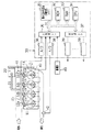
以下、この発明を具体化した一実施の形態について図面に従って説明する。本実施の形態では、車載ディーゼル機関用のコモンレール式燃料噴射制御装置を対象に本発明を具体化している。
【0033】
はじめに図1を参照して、こうしたコモンレール式燃料噴射制御装置の構成並びに動作を簡単に説明する。
同図1に示されるように、本実施の形態の燃料噴射制御装置は、大きくは、ディーゼル機関10に燃料を供給する燃料噴射弁12(12a〜12d)、コモンレール(畜圧室)20、燃料ポンプ22、各種センサ、そしてそれらのセンサの出力に基づいてこれらを制御する電子制御ユニット30を備えて構成される。
【0034】
ここで、上記燃料噴射弁12(12a〜12d)は、電磁駆動式の開閉弁であり、多気筒内燃機関であるディーゼル機関10の各気筒11(11a〜11d)に対してそれぞれ配設されている。すなわち、この燃料噴射弁12(12a〜12d)は、その内部に形成された電磁弁(図示略)に、電子制御ユニット30を通じて生成された制御信号が印加されることによって開閉駆動されるようになっている。また、これら燃料噴射弁12(12a〜12d)は、畜圧室であるとともに、燃料の分配管でもあるコモンレール20に接続されている。そしてこのコモンレール20には、燃料供給管21を介して燃料ポンプ22が接続されている。この燃料ポンプ22は、ディーゼル機関10の出力軸であるクランク軸13の回転に基づいてポンプ動作を行う機関駆動式の高圧ポンプであり、図示しない電磁スピル弁等の開閉制御と協働してコモンレール20内部への燃料の吐出量およびその燃料圧力を調整している。
【0035】
一方、電子制御ユニット30は、双方向バス31により互いに接続されたROM(読み出し専用メモリ)32、RAM(随時書き込み読み出しメモリ)33、CPU(中央処理装置)34、およびEEPROMやフラッシュメモリ等の書き込み可能な不揮発性メモリ35を備えている。またこれら各要素は、上記双方向バス31により、入力ポート36および出力ポート37とも接続されている。
【0036】
そして、上記クランク軸13の近傍には、その回転角(回転速度)を検出するためのNEセンサ40が設けられており、この出力は図示しない波形整形回路を介して2値化された後、電子制御ユニット30の上記入力ポート36に取り込まれる。その他にも、ディーゼル機関10の運転状態を検出するセンサとしては、コモンレール20内の燃料圧力を検出するコモンレール圧(燃料圧)センサ41や、ディーゼル機関10の排気通路に設けられる空燃比センサ42等が設けられている。これら各センサの出力は、電子制御ユニット30内に設けられているA/D変換器38を介して上記入力ポート36に取り込まれる。また本実施の形態では、後述する燃料噴射弁12(12a〜12d)の劣化判定処理に際し、その判定タイミングの指標とするパラメータとして、上記ディーゼル機関10を搭載する車両の走行距離を採用している。そこで、本実施の形態では、この車両の走行距離を計測する距離計43の出力も、電子制御ユニット30の上記入力ポート36に取り込むようにしている。
【0037】
こうして各種センサの出力が取り込まれる電子制御ユニット30では、上記ROM32に記憶されている制御プログラムや初期データ、制御マップ等に従ってCPU34が所定の演算処理を実行する。そして、その演算結果がRAM33や書き込み可能な不揮発性メモリ35に格納されるとともに、適宜上記出力ポート37に出力される。例えばこの演算結果が、上記燃料噴射弁12による燃料噴射態様を制御するものであった場合、同演算結果はその駆動指令として、上記出力ポート37を介して駆動回路39に伝達される。このとき駆動回路39では、この伝達される駆動指令に基づいて、上記燃料噴射弁12(12a〜12d)の別にそれぞれ対応する制御信号を生成し、該生成した制御信号にてそれら燃料噴射弁12を駆動する。
【0038】
このように、本実施の形態の燃料噴射制御装置では、電子制御ユニット30から燃料噴射弁12に制御信号が印加されることによって燃料噴射弁12のディーゼル機関10に対する燃料噴射態様、すなわち燃料噴射時期および燃料噴射量(期間)が制御される。
【0039】
ところで前述のように、上記燃料噴射弁12は、その機械構造上、電子制御ユニット30からの制御信号の印加に基づく駆動開始から噴射開始までにタイムラグが生じる。そのため、電子制御ユニット30は、予めこうしたタイムラグを考慮して、燃料噴射開始に必要とする駆動時間を最少駆動時間として保持しつつ、この最少駆動時間に基づき上記制御信号の印加時期を決定することで、燃料噴射態様を制御している。
【0040】
さらに本実施の形態にあって、電子制御ユニット30は、上記最少駆動時間が燃料噴射弁12の経時変化等によって変動する場合であっても所定の燃料噴射態様が維持されるように、上記車両の走行距離を指標とした任意のタイミングで、上記燃料噴射弁12の劣化判定処理を実行する。この劣化判定処理の実行にあたってはまず、燃料噴射弁12による燃料噴射量に応じた出力変化が得られるセンサを用いて、各気筒の燃料噴射弁12の別に、初期段階の一定の燃料噴射量に基づくセンサ出力値を検出する。そして、燃料無噴射時の同センサの出力値との対比のもとに、各燃料噴射弁12の初期段階の特性を示す初期値ΔSiを算出して、これを上記書き込み可能な不揮発性メモリ35に格納しておく。一方、こうした初期値算出処理とは別に、上記任意のタイミングにて、上記初期値ΔSiを算出したときと同一の条件で、各燃料噴射弁12のその都度の特性を示す現状値ΔSを算出する。そして、この得られた現状値ΔSと上記書き込み可能な不揮発性メモリ35に保持されている初期値ΔSiとを比較することによって、それぞれ該当する燃料噴射弁の劣化判定が行われる。すなわち、同一気筒の燃料噴射弁12に対し、上記同一条件にて算出される初期値ΔSiおよび現状値ΔSは、基本的に一致するはずであり、そうでなければ燃料噴射弁12が経時変化(劣化)しているものと判断することができる。そして本実施の形態では、燃料噴射弁12がこうして劣化していると判断される場合に限って、その経時変化度合いに合わせた最少駆動時間の学習更新を実行する。
【0041】
なお、本実施の形態において、上記各燃料噴射弁12(12a〜12d)の個体差については、例えば上記初期値ΔSiや現状値ΔSを求める際の上記一定の燃料噴射量を調整するなど、予め他の方法にて吸収されているものとする。また、学習更新される以前の最少駆動時間の値としては、例えば設計仕様値や予め実験等により得られた値が用いられ、この値が上記書き込み可能な不揮発性メモリ35に予め格納されている。
【0042】
以下、電子制御ユニット30が実行する初期値算出処理、劣化判定処理、および学習更新処理について、図2〜図5を併せ参照して詳細に説明する。
なおここでは、上記燃料噴射弁12による燃料噴射量に応じた出力変化が得られるセンサとして上記NEセンサ40を使用している。ちなみに、このNEセンサ40の出力値は、その時々におけるクランク軸13のクランク角(位置)を示すが、これを時間と関連づけることで、燃料の噴射量に応じた出力変化として読み込むことができる。すなわち、燃料噴射量が増えればクランク軸13の回転速度も増し、単位クランク角の回転に要する時間は減少する。また、燃料噴射量が減少すればクランク軸13の回転速度も減少し、単位クランク角の回転に要する時間は増加する。ここで、上記単位クランク角とは、例えば上死点(TDC)〜上死点後(ATDC)50°といった具合に、任意に設定可能な角度である。
【0043】
また、こうした初期値算出処理、劣化判定処理、および学習更新処理は上述のように、各気筒の燃料噴射弁12(12a〜12d)の全てについて各別に実行される。すなわち実際には、燃料噴射弁12の一つひとつが噴射圧(コモンレール圧)別に噴射特性を持っており、上記最少駆動時間も、それら噴射圧の別に存在している。このため、それら燃料噴射弁12(12a〜12d)の別にこうした初期値算出処理、劣化判定処理、および学習更新処理を行う必要がある。ただし、以下では説明の便宜上、上記燃料噴射弁12のうちの任意の1つを対象に実行されるそれら処理の具体例のみを例示する。
【0044】
先ず、図2および図3を参照して上記初期値ΔSiを算出する処理、すなわち初期値算出処理について説明する。
この初期値ΔSiの算出は、燃料噴射弁12の取付時や交換時など、該燃料噴射弁12が初期状態にあるときに1度だけ実行される。すなわち、図2に示されるように、電子制御ユニット30は、ステップS101にて燃料噴射弁12が上記初期状態にあり、且つ初期値ΔSiを検出してないこと(S101:YES)を条件に、初期値ΔSiの算出処理を実行する。一方、燃料噴射弁12が初期状態にない場合や、すでに初期値ΔSiが算出されている場合(S101:NO)には、本処理は終了される。
【0045】
そして、上記ステップS101において、燃料噴射弁12が初期状態にあることが判定された場合には、電子制御ユニット30は、続くステップS102にて燃料噴射弁12の燃料無噴射時に相当するNEセンサ40のセンサ出力値S0を取得する。また同様に、続くステップS103では、上述した一定の燃料噴射量に対応する所定のパラメータP1(書き込み可能な不揮発性メモリ35に記憶保持)にて燃料噴射弁12を駆動したときのNEセンサ40のセンサ出力値S1を取得する。そしてその後、電子制御ユニット30は、ステップS104にて、上記ステップS102およびステップS103にて取得した無噴射時のセンサ出力値S0とパラメータP1にて燃料噴射弁12を駆動したときのセンサ出力値S1との差の値として、上記初期値ΔSiを算出して本処理を終了する。なお、この算出された初期値ΔSiは、上記書き込み可能な不揮発性メモリ35に記憶保持される。また、上記各ステップS101〜ステップS104の処理、および書き込み可能な不揮発性メモリ35によって初期値保持手段が構成される。
【0046】
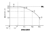
図3に上記燃料噴射量、すなわち燃料噴射弁通電時間と上記センサ出力値との関係、およびセンサ出力値の取得態様について、その一例をグラフとして示す。ちなみに、図2の上記ステップS102にて取得されるセンサ出力値S0が図3(a)の縦軸に示される「S0」の値に相当し、また上記ステップS103にて取得されるセンサ出力値S1が同じく図3(a)の縦軸に示される「S1」の値に相当する。そして、図2の上記ステップS104にて算出される初期値ΔSiは、図3(a)において横軸のパラメータP1に対応して示される差分「ΔSi」に相当する。
【0047】
なお、図3(a)の横軸は、燃料噴射弁12への通電時間を示しており、縦軸は、この通電時間(燃料噴射量)に対応した上述したNEセンサ40のセンサ出力値を示している。ちなみにこのセンサ出力値は、NEセンサ40としての出力特性上、閾値Lを出力変化のベースラインとして、その上方に向かうほど変化量は大きくなる。換言すれば、閾値Lより上方に出力されるほど、噴射量は増加しているといえる。
【0048】
そして、上記センサ出力値S0、すなわち図3(a)の「A」点に対応する値は、燃料無噴射状態で検出した上記NEセンサ40のセンサ出力値に相当する。また上記パラメータP1に対応して取得されるセンサ出力値S1、すなわち図3(a)の「B」点に対応する値は、車両減速時などのフューエルカット期間中に、同パラメータP1に基づく燃料噴射を行ったときに上記NEセンサ40が検出したセンサ出力値に相当する。
【0049】
続いて、上記算出、保持された初期値ΔSiを用いて実行される燃料噴射弁12の劣化判定処理について、図4に示すフローチャートを参照して説明する。
この劣化判定処理に際しては、先ずはじめに、ステップS201にて、劣化判定タイミングに達したか否かが判断される。この判定タイミングとしては、燃料噴射弁12による燃料噴射量の経時変化を監視し得る任意のタイミングを採用することが可能であるが、本実施の形態では上述のように、上記車両が予め定められた一定距離を走行したか否か、すなわち上記距離計43を通じて計測される距離が一定距離に達したか否かが判断される。そして、このステップS201において、該劣化判定タイミングに未だ達していないと判断される場合(S201:NO)、電子制御ユニット30は、以下に説明する劣化判定処理や学習更新処理等を実行せず、そのまま上記保持されている上記最少駆動時間に基づく燃料噴射制御を実行する(S400)。一方、上記劣化タイミングに達したと判断される場合(S201:YES)には、続くステップS210以降の現状値取得処理が実行される。
【0050】
この現状値取得処理において、電子制御ユニット30は、上述したフューエルカット期間に、ステップS210にて、燃料噴射弁12の燃料無噴射時に相当するNEセンサ40のセンサ出力値S0を先ず取得する。そして、続くステップS220にて、先の初期値算出処理(図2)にて用いたパラメータP1にて燃料噴射弁12を駆動し、そのときのNEセンサ40のセンサ出力値S1を取得する。その後、ステップS230にて、これらステップS210およびステップS220にてそれぞれ取得したセンサ出力値S0とセンサ出力値S1との差の値として、燃料噴射弁12の現状値ΔSを算出する(図3(a)参照)。なお、これらステップS201〜ステップS230の処理および上記書き込み可能な不揮発性メモリ35によって、現状値取得手段が構成される。
【0051】
さらに、ステップS240では、こうして算出した現状値ΔSが、上記算出し、保持されている初期値ΔSiに対して所定の範囲を超えてずれていないか否かが確認される。なお、ここでいう所定の範囲とは、燃料噴射弁12の劣化度合い(経時変化度合い)に対する許容値の範囲を示しており、本実施の形態では、以下の式によって該現状値ΔSのレベルが判定される。
【0052】
【数1】
(初期値ΔSi−α)<現状値ΔS<(初期値ΔSi+β)
ちなみに、上式のαおよびβの値は、任意の数値であり、燃料噴射弁12の特性等に応じて調整してもよい。またこれらαおよびβの値として、基本的には同一の値が用いられるが、燃料噴射弁12の劣化傾向や、以下に説明する学習更新処理の促進要求等に応じて異なる値を用いるようにしてもよい。なお、このステップS240によって比較手段が構成される。
【0053】
そして、このステップS240において、上記現状値ΔSが、燃料噴射弁12の劣化度合いに対する許容値の範囲内にあるとき(S240:YES)、電子制御ユニット30は、燃料噴射弁12が劣化していない、もしくはその劣化の度合いが許容範囲にあるものと判定する。そしてこの場合も、そのまま上記保持されている最少駆動時間に基づく燃料噴射制御の実行を継続する(S400)。
【0054】
一方、同ステップS240において燃料噴射弁12が劣化していると判定する(S240:NO)と、電子制御ユニット30は、続くステップS310にて、その経時変化度合いが緩和される方向にパラメータを再設定するパラメータ再設定処理を実行する。図5に、こうしたパラメータ再設定処理について、その具体手順の一例を示す。
【0055】
同図5に示されるように、この処理では、上記現状値ΔSが初期値ΔSiを上回る方向にずれているとき(S311:YES)には、噴射量が増量する側に劣化しているものと判定する。そして、ステップS312にて、上記書き込み可能な不揮発性メモリ35に記憶保持されているパラメータP1およびP2の各値を共に燃料噴射量が所定量だけ減量される値に再設定する。一方、現状値ΔSが初期値ΔSiを下回る方向にずれているとき(S311:NO)には、噴射量が減量する側に劣化しているものと判定する。そしてこの場合には、ステップS313にて、同じく上記書き込み可能な不揮発性メモリ35に記憶保持されているパラメータP1およびP2の各値を共に燃料噴射量が所定量だけ増量される値に再設定する。なお、パラメータP1については上述したとおりであるが、上記書き込み可能な不揮発性メモリ35には、先の図3(a)に示される燃料噴射弁通電時間についてのパラメータP2に相当する値が、上記パラメータP2として併せて記憶されている。また、これらパラメータP1、P2について上記再設定が行われた場合には、これら再設定されたパラメータP1、P2にて元のパラメータが更新され、これら更新されたパラメータP1、P2が書き込み可能な不揮発性メモリ35に新たに記憶保持される。
【0056】
こうしてパラメータの再設定を行った電子制御ユニット30は、次に、図4に示すステップS320の処理として、上記再設定したパラメータP1、P2にて燃料噴射弁12を駆動し、このときのNEセンサ40のセンサ出力値S1、S2をそれぞれ取得する。そしてこれら取得した値を補間するかたちで、先の図3(a)に示されるような近似式Kを算出する(S330)。
【0057】
ちなみに、上記センサ出力値S1およびS2も、無噴射時のセンサ出力値S0と併せて、車両減速時などのフューエルカット期間中に、上記パラメータP1およびP2に基づく燃料噴射を行ったときに検出されるNEセンサ40のセンサ出力値として取得される。しかも、同取得に際しては、例えばセンサ出力値S1に反映された燃料噴射の影響が収束したと見なせるときにセンサ出力値S2が取得される。図3(a)中、横軸のパラメータP1およびP2に対応して示される「B」および「C」点は、こうして取得されるセンサ出力値S1およびS2の態様を示したものである。本実施の形態においては、上記算出される近似式Kも、同図3(a)において、これら「B」点と「C」点とを結び、その間およびその前後を補間する式として算出される。
【0058】
こうして近似式Kを算出した電子制御ユニット30は、次に同じく図3(a)に示されるように、上記燃料無噴射時のセンサ出力値S0を閾値Lとし、この閾値Lと上記算出した近似式Kとの交点Xに基づいて最少駆動時間に相当する時間を新たに算出する(S340)。なお、この最少駆動時間に相当する時間とは、図3(a)において、時刻t0を通電開始(制御信号印加)時刻とするとき、それから実際に燃料が噴射される時刻である時刻t1までの時間(t1−t0)である。
【0059】
こうして、ステップS340にて、新たな最少駆動時間を求めた電子制御ユニット30は次に、その時点で上記書き込み可能な不揮発性メモリ35に保持されている最少駆動時間を、この新たに求めた最少駆動時間にて更新する(S350)。
【0060】
そしてこれ以降、電子制御ユニット30は、この更新された最少駆動時間に基づいて前述した燃料噴射制御を実行する(S400)。なお、この新たな最少駆動時間に基づく燃料噴射制御は、再び上記劣化判定タイミングが訪れるまで、継続して実行される。
【0061】
ちなみに、本実施の形態においては、ステップS201〜ステップS240の処理が劣化判定手段となり、また、ステップS310〜ステップS350の処理が学習更新処理となる。
【0062】
また、図2〜図5を参照して詳述した以上の処理が、実際には各気筒11a〜11dに各々設けられた燃料噴射弁12a〜12dのそれぞれを対象に各別に実行されることは前述の通りである。
【0063】
以上説明したように、本実施の形態によれば、以下に列記するような多くの優れた効果を得ることができる。
(1)この実施の形態では、燃料噴射弁12による燃料噴射量の経時変化度合いに基づいて同燃料噴射弁12の劣化の有無を判定する劣化判定処理を実行する。そして、この劣化判定処理において燃料噴射弁12が劣化していると判定される場合に限って、最小駆動時間の学習更新を実行することとしたため、最少駆動時間の更新にかかる演算負荷を大幅に軽減することができる。
【0064】
(2)この実施の形態では、燃料噴射弁12の初期段階の特性を示す初期値ΔSiを算出し保持するとともに、同燃料噴射弁12のその都度の特性を示す現状値ΔSを、上記初期値ΔSiと同一の条件で算出する。そして、上記保持される初期値ΔSiと上記現状値ΔSとを比較することにより劣化判定を行っている。これにより、燃料噴射弁12の経時変化度合いを、初期値ΔSiに対する現状値ΔSの推移として的確に捉えることができるようになるため、その劣化判定精度も高く維持することができる。
【0065】
(3)この実施の形態では、現状値ΔSが初期値ΔSiに対し、その所定の範囲を超えてずれていることに基づいて燃料噴射弁12の劣化が判定されるため、燃料噴射弁12の劣化度合いに対する許容値、あるいは上記最少駆動時間を学習更新したい時期といったものを任意に調整することができる。
【0066】
(4)この実施の形態では、各別の燃料噴射量を指令するパラメータ(P1、P2)のセンサ出力値(S1、S2)から近似式Kを算出するとともに、この近似式Kが燃料無噴射時のセンサ出力値S0に差交するまでの時間に基づいて最少駆動時間を算出している。そのため、最小駆動時間を一義的に、しかもより正確に算出することができる。また、その時点で書き込み可能な不揮発性メモリ35に保持されている最少駆動時間の値をこうして算出した時間にて更新することにより、燃料噴射弁12の劣化度合い(経時変化度合い)が加味されるかたちで、正確な燃料噴射制御を維持することができる。
【0067】
(5)この実施の形態では、燃料噴射弁12の劣化判定処理に際し、その判定タイミングの指標とするパラメータとして、ディーゼル機関10を搭載する車両の走行距離を採用している。ちなみに、この走行距離として長い距離を設定するほど、演算負荷の軽減効果は向上するものの、逆に学習更新の機会は減少する。この点、この走行距離というパラメータは、このようなトレードオフの中で、その設定いかんにより、比較的その両立が図りやすいパラメータであるといえる。
【0068】
(6)この実施の形態では、燃料噴射弁12の燃料無噴射時に相当するセンサのセンサ出力値として、燃料無噴射時とみなせる期間におけるNEセンサ40のセンサ出力値S0、すなわち実測値を採用している。そのため、劣化判定や学習更新にかかる信頼性を高く維持することができる。
【0069】
(7)この実施の形態では、NEセンサ40のセンサ出力値(S1、S2)に基づいて近似式Kを求めるに際し、センサ出力値S2は、少なくともセンサ出力値S1を取得したときのディーゼル機関10の運転環境に一致する条件で、特にここでは車両減速時などのフューエルカット期間中に取得することとした。これにより、NEセンサ40のセンサ出力値(S1、S2)に直接影響する測定環境の違いが解消され、より高い精度にて上記近似式Kを求めることができる。
【0070】
(8)この実施の形態では、NEセンサ40のセンサ出力値(S1、S2)の取得に際し、センサ出力値S1に反映された燃料噴射の影響が収束したと見なせるときにセンサ出力値S2を取得することとした。これにより、取得されるセンサ出力値(S1、S2)の一つひとつがより信頼性の高い値となり、ひいては上記求められる近似式Kの精度も更に高めることができる。なお、これらセンサ出力値S1、S2の取得順は逆であってもよい。
【0071】
(9)この実施の形態では、初期値算出処理、劣化判定処理および学習更新処理を、各気筒の燃料噴射弁12(12a〜12d)の全てにおいて各別に実行するため、演算負荷を最小限に抑えつつ、多気筒内燃機関全体としての燃料噴射制御も常に適正に維持することができる。
【0072】
(10)この実施の形態では、より正確に最少駆動時間を把握することができるため、より木目細かな制御信号の生成を必要とするマルチ噴射等にも的確に対応することができる。
【0073】
なお、この発明にかかる燃料噴射制御装置は、上記実施の形態に限定されるものではなく、同実施の形態を適宜変更した、例えば次のような形態として実施することもできる。
【0074】
・上記実施の形態では、燃料無噴射時のセンサ出力値S0とパラメータP1にて燃料噴射弁12を駆動したときのセンサ出力値S0との差によって初期値ΔSiおよび現状値ΔSを算出した。こうした初期値ΔSiおよび現状値ΔSは、燃料無噴射時のセンサ出力値S0とパラメータP1にて燃料噴射弁12を駆動したときのセンサ出力値S0との比によっても算出することができる。
【0075】
・さらに、初期値ΔSiおよび現状値ΔSを算出する前に例えばパラメータP2のセンサ出力値S2を取得している場合には、以下の態様によっても初期値ΔSiおよび現状値ΔSを算出することができる。
【0076】
(A1)センサ出力値S0とセンサ出力値S2との差。
(A2)センサ出力値S0とセンサ出力値S2との比。
(A3)センサ出力値S1とセンサ出力値S2との差。
【0077】
(A4)センサ出力値S1とセンサ出力値S2との比。
・上記実施の形態では、現状値ΔSが初期値ΔSiに対し所定の範囲を超えてずれていることに基づいて燃料噴射弁12が劣化している旨を判定した。しかし、こうした劣化判定の仕方自体は任意であり、単に現状値ΔSと初期値ΔSiを比較することによってのみでも、その差分あるいは比に基づいて劣化の有無を判定することは可能である。
【0078】
・上記実施の形態では、各別の燃料噴射量を指令するパラメータP1およびパラメータP2にて燃料噴射弁12を駆動したときにNEセンサ40を通じて検出されるセンサ出力値S1およびセンサ出力値S2を補間する態様にて近似式Kを算出することとした。こうしたパラメータは、演算負荷の許容範囲内において、その数を任意に増設してもよい。例えばパラメータP2よりも多い噴射量を指令するパラメータP3を更に設定して、このパラメータP3に対応するセンサ出力値S3を取得し、これら3つ(あるいはそれ以上)のセンサ出力値から上記近似式Kを求めるようにしてもよい。そうした場合には、近似式Kの精度、ひいてはそこから算出される最少駆動時間の精度をさらに向上させることができる。
【0079】
・上記実施の形態では、上記各センサ出力値の取得を、車両減速時などのフューエルカット期間中に行うことととしたが、これに代えて、通常の燃料噴射制御時にそれらセンサ出力値の取得を行う構成とすることもできる。すなわちこの場合、上記パラメータP1に対応して取得されるセンサ出力値S1、すなわち先の図3(a)の「B」点に対応する値は、例えば図3(b)に示すように、車両の減速運転中や加速運転中といったフューエルカット期間以外の機関運転中に求められる。逆に、燃料無噴射時のセンサ出力値S0、すなわち図3(a)の「A」点に対応する値は、図3(b)に示すように、フューエルカット期間中に求められる。また、近似式Kの算出に際しても、上記センサ出力値S1およびS2は、無噴射時のセンサ出力値S0と併せて、図3(b)に例示するようなフューエルカット期間を含む減速運転および加速運転を複数回繰り返す中で取得される。そして、上記センサ出力値S0が同図3(b)中、「A」の点で、また上記センサ出力値S1が同図3(b)中、「B」の点で取得されるとするとき、上記センサ出力値S2は、
(i)少なくとも上記センサ出力値S1を取得したときのディーゼル機関10の運転環境に一致していること。且つ、
(ii)該センサ出力値S1に反映された燃料噴射の影響が収束したと見なせること。
を条件に、上記パラメータP2に対応するセンサ出力値として、同図3(b)中の減速運転中、あるいは加速運転中の適宜のタイミングで取得される。これにより、図3(a)に示すパラメータP2に対応したセンサ出力値S2として「C」点の取得が可能となる。そしてこの場合、上記算出される近似式Kも、同図3(a)において、この「C」点と上記「B」点とを結び、その間およびその前後を補間する式として算出される。
【0080】
・またこの場合、センサ出力値に基づいて近似式を求めるに際し、センサ出力値(S1、S2、…)を、ディーゼル機関10のそれぞれ一致する運転環境のもとで取得することとしたが、近似式を求める上で所望とする精度が維持可能であれば、こうしたセンサ出力値(S1、S2、…)の取得条件を緩和してもよい。また同様に、センサ出力値(S1、S2、…)の取得に際しては、センサ出力値(S1、S2、…)が各々、他のセンサ出力値に反映された燃料噴射の影響が収束したと見なせるときに取得することとした。これも各センサ出力値(S1、S2、…)の信頼性が維持できる範囲であれば、こうした取得条件を緩和することができる。なお、センサ出力値S0も含めて、これらセンサ出力値(S1、S2、…)の取得条件については、先の初期値算出処理や劣化判定処理に関しても同様のことがいえる。
【0081】
・上記実施の形態では、燃料噴射弁12による燃料噴射量に応じた出力変化が得られるセンサとしてNEセンサ40を採用した。しかし、こうしたセンサはNEセンサ40には限られない。例えば図1に示したように、排気ガスの酸素濃度をセンサ出力値として出力する空燃比センサ42のほか、ディーゼル機関10の燃焼圧力をセンサ出力値として出力するもの、機関本体に生じる振動や加速度等、その運動エネルギをセンサ出力値として出力するものなどを採用してもよい。例えば図6には、上記NEセンサ40に代えて、空燃比センサ42(排気中の酸素濃度推移に対してリニアな値を出力するタイプのもの)を採用した場合の燃料噴射弁通電時間(燃料噴射量)とセンサ出力値との関係を例示している。同図6に示されるように、燃料噴射弁12への通電時間が伸長されるほど、空燃比はリッチとなることから、このときの同空燃比センサ42のセンサ出力値は燃料無噴射時のセンサ出力値S0よりも小さな値となる。このような態様でセンサ出力値が取得される場合でも、それらセンサ出力値S1、S2、およびS3に基づいて近似式を算出することができ、さらには該算出された近似式と上記閾値Lとの交点とに基づいて最少駆動時間を算出することができる。
【0082】
・上記実施の形態では、燃料噴射弁12が劣化判定されたとき、その経時変化度合いが緩和される方向に再設定されたパラメータ(P1、P2、…)にて当該燃料噴射弁12を駆動したときのセンサの出力値(S1、S2、…)をそのまま用いて、その噴射特性を補間する近似式を求めることとした。しかし、当該燃料噴射弁12において、その噴射特性がある一定の傾向を持つことが既知である場合には、上記センサの出力値(S1、S2、…)により、その既知である噴射特性(傾向)を補正するかたちで、同噴射特性を補間する近似式を求めるようにしてもよい。
【0083】
・上記実施の形態では、図1に例示した距離計43を用いて車両の走行距離を計測することとしたが、他に例えば、車両に通常搭載される車速センサの出力を電子制御ユニット30に取り込み、この車速センサの出力から車速を求めるとともに、この求めた車速から上記走行距離を算出するようにしてもよい。
【0084】
・上記実施の形態では、劣化判定処理を実施するタイミングの指標とするパラメータとして、上記車両の走行距離を採用したが、これに代えて、ディーゼル機関10の稼働時間や燃料噴射弁12の駆動回数なども採用することができる。このような構成を採用する場合には、これら稼働時間や駆動回数をカウントするための計時手段、あるいはカウンタ等を適宜設けることとなる。
【0085】
・上記の実施の形態では、車載ディーゼル機関10を対象に本発明を具体化したが、本発明は、ディーゼル機関に限定されることなく、例えば希薄燃焼を実施するガソリン機関に採用することもできる。すなわち、希薄燃焼を実施する際には、気流生成過程における適切な時期に適切な量の燃料を噴射する必要がある。この点、本発明によれば、劣化判定処理および学習更新処理等によって正確な最少駆動時間を把握することができるため、そうした態様での燃料噴射制御についても好適に対応することができる。
【0086】
・また、上記実施の形態では、燃料噴射弁として電磁駆動式の燃料噴射弁12を採用したが、圧電素子駆動式の燃料噴射ノズル(ピエゾインジェクタ)等も適宜採用可能である。要は、その駆動時期や駆動期間が電子制御されるいわゆる電子制御式の燃料噴射弁であれば、本発明にかかる燃料噴射制御装置を適用することはできる。
【図面の簡単な説明】
【図1】本発明にかかる燃料噴射制御装置の一実施の形態についてその概略構成を示すブロック図。
【図2】同実施の形態の初期値算出処理についてその処理手順を示すフローチャート。
【図3】(a)はセンサ出力値と燃料噴射弁への通電時間との関係を示すグラフ。(b)は車両の運転推移を示す時間と燃料噴射量との関係を示すグラフ。
【図4】同実施の形態の劣化判定処理および学習更新処理についてその処理手順を示すフローチャート。
【図5】同実施の形態のパラメータ再設定処理についてその処理手順を示すフローチャート。
【図6】上記センサ出力値と燃料噴射弁への通電時間との関係についての変形例を示すグラフ。
【符号の説明】
10…ディーゼル機関、11(11a〜11d)…気筒、12(12a〜12d)…燃料噴射弁、13…クランク軸、20…コモンレール、21…燃料供給管、22…燃料ポンプ、30…電子制御ユニット、31…双方向バス、32…ROM、33…RAM、34…CPU、35…書き込み可能な不揮発性メモリ、36…入力ポート、37…出力ポート、38…A/D変換器、39…駆動回路、40…NEセンサ、41…コモンレール圧センサ、42…空燃比センサ、43…距離計。[0001]
BACKGROUND OF THE INVENTION
The present invention relates to a fuel injection control device for an internal combustion engine that controls an aspect of fuel injection to the internal combustion engine using an electronically controlled fuel injection valve.
[0002]
[Prior art]
In recent years, in diesel engines, common-rail high-pressure fuel injection that injects high-pressure fuel stored in a common rail (stock pressure chamber) into an engine combustion chamber by applying an electronically controlled control signal to an electromagnetically driven fuel injection valve. A system (hereinafter referred to as a common rail system) is often adopted. In such a common rail system, it is basically possible to directly control the opening and closing of the fuel injection valve without depending on the engine speed, so the fuel injection pressure, fuel injection amount, fuel injection timing, etc. are set independently. be able to.
[0003]
Therefore, in a diesel engine that employs this common rail system, so-called multi-stage injection (multi-injection), in which a plurality of micro injections are performed per combustion cycle, is performed to reduce smoke, nitride oxide (NOx), and the like. Is also easy. Incidentally, as an example of such multi-injection, for example, in pilot injection in which a part of fuel injected in main injection is injected in advance prior to main injection, a sudden increase in combustion pressure or combustion temperature during main combustion due to main injection occurs. Since it can suppress, reduction of a combustion noise and suppression of NOx are achieved. In addition, for example, pre-injection or after-injection that injects a small amount of fuel at close periods before and after the main injection makes it possible to further promote combustion by the main injection and suppress the occurrence of smoke and the like. Is done. In addition, in the post-injection in which the fuel is injected at a time that is largely retarded with respect to the main injection, that is, in the latter half of the combustion stroke, the catalyst is easily activated by raising the temperature of the exhaust gas or supplying the reducing component, thereby improving the exhaust emission. .
[0004]
On the other hand, as is well known, an electromagnetically driven fuel injection valve is driven to open and close when the control signal is applied to the fuel injection valve. That is, the solenoid valve of the fuel injection valve is driven so that the nozzle is opened by application (energization) of a control signal, and fuel injection is started when the nozzle is opened. On the other hand, the electromagnetic valve is driven so that the nozzle is closed by the application release (interruption of electric power) of the control signal, and the fuel injection is stopped when the nozzle is closed.
[0005]
By the way, when the fuel injection mode is controlled using such an electromagnetically driven fuel injection valve, it is necessary to consider the time lag from the start of driving to the start of injection. That is, due to the mechanical structure of the fuel injection valve, there is a time lag from the start of driving to the start of injection due to a response delay of the valve body. Therefore, in consideration of such a time lag, it is possible to carry out fuel injection control at an assumed amount by preliminarily grasping the drive time required for starting fuel injection as the minimum drive time. Become. In particular, in the above-described multi-injection, it is necessary to generate a finer control signal in order to realize micro-injection, and therefore it is essential to accurately grasp the minimum drive time.
[0006]
However, even if the minimum drive time is once grasped, the minimum drive time often fluctuates due to a change with time including deterioration of the fuel injection valve. In addition, such a minimum driving time may differ for each cylinder of the multi-cylinder internal combustion engine due to manufacturing tolerances of the fuel injection valve.
[0007]
Therefore, conventionally, as shown in
[0008]
On the other hand, when the detected output value of the HC sensor is smaller than the reference value (value at the time of non-injection), the minimum drive is performed so that the held minimum drive time is extended by a predetermined time. Time is temporarily corrected. In this case as well, the output value of the HC sensor when the fuel injection is performed is detected again based on the temporarily corrected minimum drive time. This process is also repeated until the detected output value of the HC sensor becomes larger than the reference value, and the value of the minimum drive time temporarily corrected when the output value of the sensor becomes larger than the reference value. However, the minimum drive time of the fuel injection valve is reset (learned and updated).
[0009]
The correction of the minimum driving time, that is, the learning update is repeatedly performed in order for each cylinder, so that compensation for changes with time and the like is continuously maintained for the fuel injection valves of all the cylinders.
[0010]
[Patent Document 1]
JP 11-294227 A
[0011]
[Problems to be solved by the invention]
As described above, by correcting (learning and updating) the minimum drive time using the output value of the HC sensor, a desired mode can be obtained even when the fuel injection valve has changed over time such as deterioration. It is possible to execute the fuel injection control.
[0012]
However, in such a method, the above-described comparison process and the like are repeated while trying the fuel injection several times until the required minimum driving time is obtained, so the increase in calculation load for calculating the minimum driving time is ignored. It is impossible.
[0013]
Further, the value of the minimum driving time to be corrected is also corrected in such a manner that it is decreased if the sensor output value detected first is larger than the reference value, and is increased if it is smaller than the reference value. . Therefore, even if correction deviating from the original minimum driving time is performed, if these conditions are satisfied, it will be regarded as the minimum driving time, and there will still be problems in terms of correction accuracy. ing.
[0014]
Further, since the fuel injection amount is small immediately after the start of fuel injection, the output change of the HC sensor is small, and it is easily affected by disturbance. Therefore, the conventional method described above also makes it difficult to accurately grasp the minimum driving time.
[0015]
The present invention has been made in view of such circumstances, and an object of the present invention is to provide a fuel injection control device capable of greatly reducing the calculation load when updating the minimum drive time of the fuel injection valve. It is in.
[0016]
It is another object of the present invention to provide a fuel injection control device that can obtain a minimum driving time with a minimum calculation load and higher accuracy when updating the minimum driving time of a fuel injection valve.
[0017]
[Means for Solving the Problems]
In order to achieve such an object, the fuel injection control device for an internal combustion engine according to
Thus, an approximate expression is obtained, and a time corresponding to the minimum drive time is newly calculated based on the intersection of the obtained approximate expression and the sensor output value (S0) of the sensor corresponding to the time of no fuel injection.It is configured.
As a result, the learning update of the minimum driving time is executed only when the deterioration determining means determines that the fuel injection valve is deteriorated, and the calculation load as the fuel injection control device is minimized. Will be able to.
Further, the fuel injection device includes a sensor capable of obtaining an output change according to the fuel injection amount by the fuel injection valve, and the deterioration determination means includes:
(A) The sensor output value of the sensor corresponding to no fuel injection of the fuel injection valve, and the sensor output value of the sensor when the fuel injection valve is driven with a predetermined parameter for commanding a constant fuel injection amount Initial value holding means for acquiring and holding the difference or ratio as an initial value.
(B) The sensor output value of the sensor corresponding to the time of no fuel injection of the fuel injection valve and the predetermined parameter at an arbitrary timing at which a change over time of the fuel injection amount by the fuel injection valve can be monitored. Current value acquisition means for acquiring a difference or ratio with a sensor output value of the sensor when the fuel injection valve is driven as a current value.
(C) Comparison means for determining whether or not the fuel injection valve has deteriorated based on a comparison between the initial value and the current value.
Are provided. According to such a configuration of the deterioration determination means, the degree of change over time of the fuel injection valve can be accurately grasped as a transition of the current value with respect to the initial value, and the deterioration determination accuracy is naturally maintained high. Become so.
Furthermore, the fuel injection control apparatus employs the following mechanism when learning and updating the minimum drive time. That is,
(A) At least two predetermined parameters (P1, P2,...) For commanding different fuel injection amounts are held in at least one of the initial value holding means and the current value acquisition means. (B) When the current value deviates in a direction less than the initial value, the predetermined parameters (P1, P2,...) Are reset to a direction in which the fuel injection amount is increased by a predetermined amount, and the current value is set. When the value deviates in the direction exceeding the initial value, the predetermined parameters (P1, P2,...) Are reset to the direction in which the fuel injection amount is reduced by a predetermined amount, and the fuel injection valves are driven. The sensor output value (S1, S2,...) Of the sensor is obtained.
(C) An approximate expression is obtained by interpolating the sensor output values (S1, S2,...) Of these acquired sensors.
(D) A time corresponding to the minimum drive time is newly calculated based on the intersection of the obtained approximate expression and the sensor output value (S0) of the sensor corresponding to the time of no fuel injection.
Here, in particular, once the approximate expression is obtained in the above-described mode (c), the injection characteristics of the fuel injection valve become substantially clear thereafter without depending on the sensor output. Therefore, the control signal is also applied to the fuel injection valve for the drive time required for starting the fuel injection, that is, the minimum drive time, using the sensor output value (S0) of the sensor corresponding to the time of no fuel injection as a threshold. The time until the approximate expression crosses the sensor output value (S0) of the sensor can be calculated uniquely and more accurately. Then, by updating the value of the held minimum driving time at the calculated time, accurate fuel injection control that takes into account the degree of deterioration of the fuel injection valve will be maintained thereafter. .
[0019]
Claims2In the fuel injection control device described in the above, the fuel injection valve is deteriorated based on the fact that the present value is shifted beyond a predetermined range with respect to the initial value for the comparison means constituting the deterioration determination means. It is configured to determine whether or not According to such a configuration of the comparison means, the threshold for the degree of change of the fuel injector with time, that is, the allowable value for the degree of deterioration of the fuel injector, or the minimum drive is set through the setting of the predetermined range with respect to the initial value. It is possible to arbitrarily adjust the time when it is desired to learn and update the time, and the degree of freedom in system operation as a fuel injection control device is naturally increased.
[0022]
Meanwhile, claims3In the fuel injection control device for an internal combustion engine described in 1), an electronic control type that is driven by a control signal, has a time lag from the start of driving to the start of injection, and performs fuel injection at an injection amount corresponding to the driving time after the start of injection. An internal combustion engine that determines the drive time of the fuel injection valve based on the minimum drive time while holding the drive time required for starting the fuel injection by the fuel injection valve as the minimum drive time As the fuel injection control device, there is provided a deterioration determining means for determining whether or not the fuel injection valve has deteriorated based on the degree of change with time of the fuel injection amount by the fuel injection valve. When deterioration of the fuel injection amount is determined, at least two predetermined parameters (P1, P2,. Each value (S1, S2,...) Corresponding to the fuel injection amount when reset in the summed direction is acquired, and an approximate expression is obtained by interpolating the acquired values (S1, S2,...) A time corresponding to the minimum drive time is newly calculated based on the intersection of the obtained approximate expression and a value (S0) corresponding to no fuel injection, and the minimum drive time to be held is learned and updated. Even with such a configuration, the learning update of the minimum drive time is executed only when the deterioration determination means determines the deterioration of the fuel injection valve, and the calculation load as the fuel injection control device is minimized. It becomes possible to limit to the limit. In addition, according to this configuration, the injection characteristic of the fuel injection valve is substantially clarified once the approximate expression is obtained in the above manner. For this reason, the drive time required for starting fuel injection in the fuel injection valve having a value corresponding to the time when no fuel is injected (S0) as a threshold, that is, the minimum drive time is also approximated after the control signal is applied. The time until the equation crosses the value (S0) can be calculated uniquely and more accurately. Then, by updating the value of the held minimum driving time at the calculated time, accurate fuel injection control that takes into account the degree of deterioration of the fuel injection valve will be maintained thereafter. .
[0023]
Here, as a value corresponding to the fuel injection amount when the above parameters (P1, P2,...) Are reset, for example, the deterioration transition (deterioration tendency) of the corresponding fuel injection valve is obtained in advance by experiments or the like. Estimated values and the like can be employed as appropriate.
[0024]
Claims4In the fuel injection control device described in the above, on the premise of the above configuration, the fuel injection control device includes a sensor capable of obtaining an output change according to the fuel injection amount by the fuel injection valve, and the deterioration determination unit includes:
(A) The sensor output value when the fuel injection valve is driven with the sensor output value of the sensor corresponding to the time when no fuel is injected by the fuel injection valve and a predetermined parameter (P1) for commanding a constant fuel injection amount. An initial value holding unit that acquires and holds a difference or ratio with the sensor output value (S1) as an initial value.
(B) The sensor output value (S0) of the sensor corresponding to the time of no fuel injection of the fuel injection valve and the predetermined parameter at an arbitrary timing at which the change over time of the fuel injection amount by the fuel injection valve can be monitored Current value acquisition means for acquiring, as a current value, a difference or ratio with a sensor output value (S1) of the sensor when the fuel injection valve is driven in (P1).
(C) Comparison means for determining whether or not the fuel injection valve has deteriorated based on a comparison between the initial value and the current value.
Are provided. According to such a configuration of the deterioration determination means, the degree of change over time of the fuel injection valve can be accurately grasped as a transition of the current value with respect to the initial value, and the deterioration determination accuracy is naturally maintained high. Become so.
[0025]
Claims5In the fuel injection control device described in the above, the fuel injection valve is deteriorated based on the fact that the present value is shifted beyond a predetermined range with respect to the initial value for the comparison means constituting the deterioration determination means. It is configured to determine whether or not According to such a configuration of the comparison means, the threshold for the degree of change of the fuel injector with time, that is, the allowable value for the degree of deterioration of the fuel injector, or the minimum drive is set through the setting of the predetermined range with respect to the initial value. It is possible to arbitrarily adjust the time when it is desired to learn and update the time, and the degree of freedom in system operation as a fuel injection control device is naturally increased.
[0026]
Claims6In the fuel injection control device according to
(E) At least two predetermined parameters (P1, P2,...) That command the different fuel injection amounts are held in at least one of the initial value holding means and the current value acquisition means.
(F) The resetting of these parameters (P1, P2,...) In the direction in which the degree of change with time of the fuel injection amount is eased is performed when the current value is shifted in a direction lower than the initial value. P1, P2,... Are reset to values that increase the fuel injection amount by a predetermined amount, and when the current value is shifted in a direction exceeding the initial value, the predetermined parameters (P1, P2,. ) Is reset in such a manner that the fuel injection amount is reduced by a predetermined amount.
(G) A value corresponding to the fuel injection amount when the parameters (P1, P2,...) Are reset.
(S1, S2,...) Are sensor output values of the sensor when the fuel injection valve is driven with the reset parameters (P1, P2,...).
The configuration is adopted. As described above, the value (S1, S2,...) Corresponding to the fuel injection amount when the parameters (P1, P2,. The estimated value obtained by experiment or the like can be adopted as appropriate, but in particular, as in this configuration, the value (corresponding to the fuel injection amount when the parameters (P1, P2,...) Are reset ( As S1, S2,..., The sensor output value of the sensor when the fuel injection valve is driven with these reset parameters (P1, P2,. Learning accuracy can be maintained high.
[0027]
Claims7In the fuel injection control device described in (1), in the configuration using the sensor, the sensor output value of the sensor corresponding to the time of no fuel injection of the fuel injection valve is the measured value of the sensor during a period that can be regarded as no fuel injection. I am doing so. With such a configuration, whether the deterioration of the fuel injection valve is determined or the learning update of the minimum driving time is performed, it is possible to maintain high reliability for the deterioration determination and the learning update.
[0028]
In addition, as such a sensor, that is, a sensor capable of obtaining an output change in accordance with the fuel injection amount by the fuel injection valve, claims8As described in the above, one that outputs the combustion pressure of the internal combustion engine as a sensor output value, one that outputs the amount of change in engine speed as a sensor output value, one that outputs the state of exhaust gas as a sensor output value, or It is possible to employ one that outputs its kinetic energy as a sensor output value, such as vibration or acceleration generated in the engine body.
[0029]
On the other hand, the claim9In the fuel injection control device described in 1), when obtaining the approximate expression based on the sensor output value of such a sensor, the sensor output values (S1, S2,...) Of those sensors are used for a fuel cut period such as during vehicle deceleration operation, for example. The configuration is such that the engine is acquired under the corresponding operating environment of the internal combustion engine including the inside. Thereby, the difference in the measurement environment that directly affects the sensor output values (S1, S2,...) Of the sensor is eliminated, and the approximate expression can be obtained with higher accuracy.
[0030]
Further claim 10In the fuel injection control device described in 1), when obtaining the sensor output value of such a sensor, the sensor output values (S1, S2,...) Of the sensor are influenced by the fuel injection reflected in the sensor output values of the other sensors. Is acquired when it can be considered that the system has converged. By adopting such a configuration, each of the sensor output values of the acquired sensors becomes a more reliable value, and as a result, the accuracy of the approximate expression obtained is further improved.
[0031]
And claim 11In the fuel injection control device for an internal combustion engine described in 1), on the assumption that the internal combustion engine is a multi-cylinder internal combustion engine and a fuel injection valve is provided for each cylinder of the internal combustion engine, the fuel by the deterioration determination means The determination of the deterioration of the injection valve and the learning update of the minimum drive time are performed separately for each fuel injection valve of each cylinder. When such a plurality of fuel injection valves are provided, the difference between the individual fuel injection valves, even if they are absorbed by some other method, the degree of change over time, that is, the degree of deterioration, is determined by the respective fuel injection valves. Usually it is different for each valve. Therefore, this claim 11As in the fuel injection control device described in the above, the calculation load is minimized by performing the deterioration determination of the fuel injection valve and the learning update of the minimum driving time separately for each fuel injection valve. The fuel injection control as a whole of the multi-cylinder internal combustion engine can always be properly maintained while suppressing.
[0032]
DETAILED DESCRIPTION OF THE INVENTION
Hereinafter, an embodiment of the present invention will be described with reference to the drawings. In the present embodiment, the present invention is embodied for a common rail fuel injection control device for an on-vehicle diesel engine.
[0033]
First, referring to FIG. 1, the configuration and operation of such a common rail fuel injection control device will be briefly described.
As shown in FIG. 1, the fuel injection control device of the present embodiment is roughly divided into a fuel injection valve 12 (12 a to 12 d), a common rail (stock pressure chamber) 20, a fuel for supplying fuel to the
[0034]
Here, the fuel injection valves 12 (12a to 12d) are electromagnetically driven on-off valves, and are respectively provided to the cylinders 11 (11a to 11d) of the
[0035]
On the other hand, the
[0036]
An
[0037]
In the
[0038]
Thus, in the fuel injection control device of the present embodiment, the fuel injection mode of the fuel injection valve 12 to the
[0039]
As described above, the fuel injection valve 12 has a time lag from the start of driving based on the application of the control signal from the
[0040]
Furthermore, in the present embodiment, the
[0041]
In the present embodiment, the individual difference between the fuel injection valves 12 (12a to 12d) is adjusted in advance, for example, by adjusting the constant fuel injection amount when the initial value ΔSi or the current value ΔS is obtained. It shall be absorbed by other methods. In addition, as the value of the minimum driving time before the learning update, for example, a design specification value or a value obtained in advance by an experiment or the like is used, and this value is stored in the writable
[0042]
Hereinafter, the initial value calculation process, the deterioration determination process, and the learning update process executed by the
Here, the
[0043]
Further, as described above, the initial value calculation process, the deterioration determination process, and the learning update process are executed separately for all the fuel injection valves 12 (12a to 12d) of each cylinder. That is, in reality, each of the fuel injection valves 12 has an injection characteristic for each injection pressure (common rail pressure), and the minimum drive time also exists for each injection pressure. For this reason, it is necessary to perform such initial value calculation processing, deterioration determination processing, and learning update processing separately for the fuel injection valves 12 (12a to 12d). However, in the following, for convenience of explanation, only specific examples of those processes executed on any one of the fuel injection valves 12 will be illustrated.
[0044]
First, the process for calculating the initial value ΔSi, that is, the initial value calculation process will be described with reference to FIGS.
The calculation of the initial value ΔSi is executed only once when the fuel injection valve 12 is in the initial state, such as when the fuel injection valve 12 is attached or replaced. That is, as shown in FIG. 2, the
[0045]
When it is determined in step S101 that the fuel injection valve 12 is in the initial state, the
[0046]
FIG. 3 is a graph showing an example of the fuel injection amount, that is, the relationship between the fuel injection valve energization time and the sensor output value, and the sensor output value acquisition mode. Incidentally, the sensor output value S0 acquired in step S102 in FIG. 2 corresponds to the value of “S0” shown on the vertical axis in FIG. 3A, and the sensor output value acquired in step S103. S1 corresponds to the value of “S1” shown on the vertical axis of FIG. The initial value ΔSi calculated in step S104 in FIG. 2 corresponds to the difference “ΔSi” shown corresponding to the parameter P1 on the horizontal axis in FIG.
[0047]
Note that the horizontal axis of FIG. 3A indicates the energization time to the fuel injection valve 12, and the vertical axis indicates the sensor output value of the
[0048]
The sensor output value S0, that is, the value corresponding to the “A” point in FIG. 3A, corresponds to the sensor output value of the
[0049]
Next, the deterioration determination process of the fuel injection valve 12 executed using the calculated and held initial value ΔSi will be described with reference to the flowchart shown in FIG.
In the deterioration determination process, first, in step S201, it is determined whether or not the deterioration determination timing has been reached. As this determination timing, it is possible to employ any timing at which the change over time of the fuel injection amount by the fuel injection valve 12 can be monitored, but in this embodiment, the vehicle is determined in advance as described above. It is determined whether the vehicle has traveled a certain distance, that is, whether the distance measured through the
[0050]
In this current value acquisition process, the
[0051]
Further, in step S240, it is confirmed whether or not the current value ΔS calculated in this way has deviated beyond the predetermined range with respect to the calculated initial value ΔSi. The predetermined range here indicates a range of an allowable value for the degree of deterioration (degree of change with time) of the fuel injection valve 12. In the present embodiment, the level of the current value ΔS is expressed by the following equation. Determined.
[0052]
[Expression 1]
(Initial value ΔSi−α) <current value ΔS <(initial value ΔSi + β)
Incidentally, the values of α and β in the above equation are arbitrary numerical values, and may be adjusted according to the characteristics of the fuel injection valve 12 and the like. The α and β values are basically the same, but different values are used according to the deterioration tendency of the fuel injection valve 12, the learning update process promotion request described below, and the like. May be. Note that this step S240 constitutes a comparison means.
[0053]
In step S240, when the current value ΔS is within the allowable value range for the degree of deterioration of the fuel injection valve 12 (S240: YES), the
[0054]
On the other hand, if it is determined in step S240 that the fuel injection valve 12 has deteriorated (S240: NO), the
[0055]
As shown in FIG. 5, in this process, when the current value ΔS is shifted in a direction exceeding the initial value ΔSi (S311: YES), the injection amount is deteriorated to increase. judge. In step S312, the values of parameters P1 and P2 stored and held in the writable
[0056]
The
[0057]
Incidentally, the sensor output values S1 and S2 are also detected when the fuel injection based on the parameters P1 and P2 is performed during the fuel cut period such as when the vehicle is decelerated, together with the sensor output value S0 when there is no injection. Obtained as the sensor output value of the
[0058]
The
[0059]
In this way, the
[0060]
Thereafter, the
[0061]
Incidentally, in the present embodiment, the processes in steps S201 to S240 serve as deterioration determination means, and the processes in steps S310 to S350 serve as learning update processes.
[0062]
In addition, the processing described above with reference to FIGS. 2 to 5 is actually executed separately for each of the
[0063]
As described above, according to the present embodiment, many excellent effects listed below can be obtained.
(1) In this embodiment, a deterioration determination process for determining whether or not the fuel injection valve 12 has deteriorated based on the degree of change with time of the fuel injection amount by the fuel injection valve 12 is executed. Then, only when it is determined that the fuel injection valve 12 is deteriorated in this deterioration determination process, the learning update of the minimum drive time is executed, so that the calculation load for updating the minimum drive time is greatly increased. Can be reduced.
[0064]
(2) In this embodiment, the initial value ΔSi indicating the initial stage characteristic of the fuel injection valve 12 is calculated and held, and the current value ΔS indicating the respective characteristic of the fuel injection valve 12 is calculated as the initial value. Calculated under the same conditions as ΔSi. Then, the deterioration is determined by comparing the held initial value ΔSi and the current value ΔS. As a result, the degree of change with time of the fuel injection valve 12 can be accurately grasped as the transition of the current value ΔS with respect to the initial value ΔSi, so that the deterioration determination accuracy can be maintained high.
[0065]
(3) In this embodiment, the deterioration of the fuel injection valve 12 is determined based on the fact that the current value ΔS deviates from the initial value ΔSi beyond its predetermined range. It is possible to arbitrarily adjust an allowable value for the degree of deterioration or a time when the minimum driving time is desired to be updated.
[0066]
(4) In this embodiment, the approximate expression K is calculated from the sensor output values (S1, S2) of the parameters (P1, P2) for instructing different fuel injection amounts, and the approximate expression K is used as the fuel non-injection. The minimum drive time is calculated based on the time until the sensor output value S0 is crossed. Therefore, the minimum driving time can be calculated uniquely and more accurately. Further, by updating the value of the minimum drive time held in the writable
[0067]
(5) In this embodiment, the travel distance of the vehicle on which the
[0068]
(6) In this embodiment, the sensor output value S0 of the
[0069]
(7) In this embodiment, when the approximate expression K is obtained based on the sensor output values (S1, S2) of the
[0070]
(8) In this embodiment, when acquiring the sensor output values (S1, S2) of the
[0071]
(9) In this embodiment, the initial value calculation process, the deterioration determination process, and the learning update process are separately executed in all the fuel injection valves 12 (12a to 12d) of each cylinder, so that the calculation load is minimized. The fuel injection control as a whole multi-cylinder internal combustion engine can always be properly maintained while suppressing.
[0072]
(10) In this embodiment, since the minimum driving time can be grasped more accurately, it is possible to accurately cope with multi-injection and the like that require more detailed control signal generation.
[0073]
Note that the fuel injection control device according to the present invention is not limited to the above-described embodiment, and can be implemented as, for example, the following embodiment, which is appropriately modified from the embodiment.
[0074]
In the above embodiment, the initial value ΔSi and the current value ΔS are calculated based on the difference between the sensor output value S0 when no fuel is injected and the sensor output value S0 when the fuel injection valve 12 is driven with the parameter P1. The initial value ΔSi and the current value ΔS can also be calculated by the ratio between the sensor output value S0 when no fuel is injected and the sensor output value S0 when the fuel injection valve 12 is driven with the parameter P1.
[0075]
Furthermore, when the sensor output value S2 of the parameter P2 is acquired before calculating the initial value ΔSi and the current value ΔS, for example, the initial value ΔSi and the current value ΔS can also be calculated in the following manner. .
[0076]
(A1) The difference between the sensor output value S0 and the sensor output value S2.
(A2) A ratio between the sensor output value S0 and the sensor output value S2.
(A3) The difference between the sensor output value S1 and the sensor output value S2.
[0077]
(A4) Ratio of sensor output value S1 and sensor output value S2.
In the above embodiment, it is determined that the fuel injection valve 12 is deteriorated based on the fact that the current value ΔS is deviated from the initial value ΔSi beyond a predetermined range. However, the method of determining such deterioration itself is arbitrary, and it is possible to determine the presence or absence of deterioration based on the difference or ratio simply by comparing the current value ΔS and the initial value ΔSi.
[0078]
In the above embodiment, the sensor output value S1 and the sensor output value S2 detected through the
[0079]
In the above embodiment, the sensor output values are acquired during a fuel cut period such as when the vehicle is decelerated. Instead, the sensor output values are acquired during normal fuel injection control. It can also be set as the structure which performs. That is, in this case, the sensor output value S1 acquired corresponding to the parameter P1, that is, the value corresponding to the “B” point in FIG. It is required during engine operation other than the fuel cut period such as during deceleration operation and acceleration operation. Conversely, the sensor output value S0 at the time of no fuel injection, that is, the value corresponding to the “A” point in FIG. 3A is obtained during the fuel cut period as shown in FIG. In calculating the approximate expression K, the sensor output values S1 and S2 are combined with the sensor output value S0 at the time of non-injection, and the deceleration operation and acceleration including a fuel cut period as illustrated in FIG. Acquired during repeated driving. When the sensor output value S0 is acquired at the point “A” in FIG. 3B and the sensor output value S1 is acquired at the point “B” in FIG. 3B. The sensor output value S2 is
(I) At least match the operating environment of the
(Ii) It can be considered that the influence of the fuel injection reflected in the sensor output value S1 has converged.
As a condition, the sensor output value corresponding to the parameter P2 is acquired at an appropriate timing during the deceleration operation or the acceleration operation in FIG. This makes it possible to acquire the “C” point as the sensor output value S2 corresponding to the parameter P2 shown in FIG. In this case, the calculated approximate expression K is also calculated as an expression that connects the “C” point and the “B” point and interpolates between and before and after the “C” point in FIG.
[0080]
In this case, when the approximate expression is obtained based on the sensor output value, the sensor output values (S1, S2,...) Are obtained under the driving environment that matches each of the
[0081]
In the above embodiment, the
[0082]
In the above embodiment, when it is determined that the fuel injection valve 12 is deteriorated, the fuel injection valve 12 is driven with the parameters (P1, P2,...) Reset so as to reduce the degree of change with time. The output value (S1, S2,...) Of the sensor at that time is used as it is, and an approximate expression for interpolating the injection characteristics is obtained. However, when it is known that the injection characteristic of the fuel injection valve 12 has a certain tendency, the known injection characteristic (trend) is determined by the output values (S1, S2,...) Of the sensor. ) May be corrected to obtain an approximate expression for interpolating the injection characteristics.
[0083]
In the above embodiment, the distance traveled by the vehicle is measured using the
[0084]
In the above embodiment, the travel distance of the vehicle is employed as a parameter as an index of timing for performing the deterioration determination process. Instead, the operation time of the
[0085]
-In above-mentioned embodiment, although this invention was actualized for the vehicle-mounted
[0086]
In the above-described embodiment, the electromagnetically driven fuel injection valve 12 is used as the fuel injection valve. However, a piezoelectric element driven fuel injection nozzle (piezo injector) or the like can be used as appropriate. The point is that the fuel injection control device according to the present invention can be applied to any so-called electronically controlled fuel injection valve whose driving timing and driving period are electronically controlled.
[Brief description of the drawings]
FIG. 1 is a block diagram showing a schematic configuration of an embodiment of a fuel injection control device according to the present invention.
FIG. 2 is a flowchart showing a processing procedure for initial value calculation processing according to the embodiment;
FIG. 3A is a graph showing the relationship between the sensor output value and the energization time to the fuel injection valve. (B) is a graph which shows the relationship between the time which shows driving | operation transition of a vehicle, and fuel injection amount.
FIG. 4 is a flowchart showing a processing procedure for deterioration determination processing and learning update processing according to the embodiment;
FIG. 5 is a flowchart showing a processing procedure for parameter resetting processing according to the embodiment;
FIG. 6 is a graph showing a modification of the relationship between the sensor output value and the energization time to the fuel injection valve.
[Explanation of symbols]
DESCRIPTION OF
Claims (11)
前記劣化判定手段は、
前記燃料噴射弁の燃料無噴射時に相当する前記センサのセンサ出力値と、一定の燃料噴射量を指令する所定のパラメータにて前記燃料噴射弁を駆動したときの前記センサのセンサ出力値との差、もしくは比を初期値として取得してこれを保持する初期値保持手段と、
前記燃料噴射弁による燃料噴射量の経時変化を監視し得る任意のタイミングで、前記燃料噴射弁の前記燃料無噴射時に相当する前記センサのセンサ出力値と、前記所定のパラメータにて前記燃料噴射弁を駆動したときの前記センサのセンサ出力値との差、もしくは比を現状値として取得する現状値取得手段と、
これら初期値と現状値との比較に基づいて前記燃料噴射弁の劣化の有無を判定する比較手段と、
を備えて構成されるとともに、
当該燃料噴射制御装置は、この劣化判定手段によって前記燃料噴射弁の劣化が判定されるとき、前記保持する最少駆動時間を学習更新するものであり、
同劣化判定手段を構成する前記初期値保持手段および前記現状値取得手段の少なくとも一方は、前記初期値あるいは前記現状値の取得に際し、各別の燃料噴射量を指令する少なくとも2つの所定のパラメータ(P1、P2、…)を保持していて、
当該燃料噴射制御装置による前記最少駆動時間の学習更新は、前記現状値が前記初期値を下回る方向にずれているときには、前記所定のパラメータ(P1、P2、…)を共に前記燃料噴射量が所定量だけ増量される方向に再設定し、前記現状値が前記初期値を上回る方向にずれているときには、前記所定のパラメータ(P1、P2、…)を共に前記燃料噴
射量が所定量だけ減量される方向に再設定してそれぞれ前記燃料噴射弁を駆動したときの前記センサのセンサ出力値(S1、S2、…)を取得するとともに、該取得したセンサのセンサ出力値(S1、S2、…)を補間して近似式を求め、この求めた近似式と前記燃料無噴射時に相当する前記センサのセンサ出力値(S0)との交点に基づいて前記最少駆動時間に相当する時間を新たに算出することにより行われる
ことを特徴とする内燃機関の燃料噴射制御装置。An electronically controlled fuel injection valve that is driven by a control signal, has a time lag from the start of driving to the start of injection, and injects fuel at an injection amount corresponding to the driving time after the start of injection, and fuel by this fuel injection valve comprising a degradation determiner means the presence or absence of degradation of the fuel injection valve based on the temporal change degree of injection quantity and a sensor output change corresponding to the fuel injection amount by the fuel injection valve is obtained, the fuel injection valve In the fuel injection control device for an internal combustion engine that determines the drive time of the fuel injection valve based on the minimum drive time while maintaining the drive time required for starting the fuel injection by the minimum drive time.
The deterioration determining means includes
The difference between the sensor output value of the sensor corresponding to no fuel injection of the fuel injection valve and the sensor output value of the sensor when the fuel injection valve is driven with a predetermined parameter for commanding a constant fuel injection amount Or initial value holding means for acquiring and holding the ratio as an initial value;
At any timing at which the change over time of the fuel injection amount by the fuel injection valve can be monitored, the fuel injection valve according to the sensor output value of the sensor corresponding to the time of no fuel injection of the fuel injection valve and the predetermined parameter Current value acquisition means for acquiring a difference or a ratio with a sensor output value of the sensor when driving as a current value;
Comparison means for determining the presence or absence of deterioration of the fuel injection valve based on a comparison between the initial value and the current value;
And configured with
The fuel injection control device learns and updates the minimum drive time to be held when the deterioration determination unit determines deterioration of the fuel injection valve ,
At least one of the initial value holding means and the current value acquiring means constituting the deterioration determining means is at least two predetermined parameters (commands) for commanding different fuel injection amounts when acquiring the initial value or the current value. P1, P2, ...)
The learning update of the minimum drive time by the fuel injection control device is such that when the current value is deviated in a direction less than the initial value, the fuel injection amount is determined together with the predetermined parameters (P1, P2,...). When the fuel cell is reset in a direction in which the amount is increased by a fixed amount and the current value is shifted in a direction exceeding the initial value, both the predetermined parameters (P1, P2,.
The sensor output values (S1, S2,...) Of the sensors when the fuel injection valve is driven by resetting in a direction in which the injection amount is reduced by a predetermined amount are acquired, and the sensor outputs of the acquired sensors are acquired. An approximate expression is obtained by interpolating values (S1, S2,...), And the minimum drive time is determined based on the intersection of the obtained approximate expression and the sensor output value (S0) of the sensor corresponding to the time of no fuel injection. A fuel injection control device for an internal combustion engine, which is performed by newly calculating a corresponding time .
請求項1に記載の内燃機関の燃料噴射制御装置。 The comparison means determines that the fuel injection valve has deteriorated based on the fact that the current value is shifted beyond a predetermined range with respect to the initial value.
The fuel injection control device for an internal combustion engine according to claim 1 .
前記燃料噴射弁による燃料噴射量の経時変化度合いに基づいて同燃料噴射弁の劣化の有無を判定する劣化判定手段を備え、該劣化判定手段にて前記燃料噴射弁の劣化が判定されるとき、各別の燃料噴射量を指令する少なくとも2つの所定のパラメータ(P1、P2、…)を前記燃料噴射量の経時変化度合いが緩和される方向に再設定したときの燃料噴射量に相当する値(S1、S2、…)をそれぞれ取得するとともに、該取得した値(S1、S2、…)を補間して近似式を求め、この求めた近似式と燃料無噴射時に相当する値(S0)との交点に基づき前記最少駆動時間に相当する時間を新たに算出して、前記保持する最少駆動時間を学習更新する
ことを特徴とする内燃機関の燃料噴射制御装置。 An electronically controlled fuel injection valve that is driven by a control signal, has a time lag from the start of driving to the start of injection, and injects fuel at an injection amount corresponding to the driving time after the start of injection. In the fuel injection control device for an internal combustion engine that determines the drive time of the fuel injection valve based on the minimum drive time while maintaining the drive time required for starting the fuel injection as the minimum drive time.
A deterioration determining means for determining whether or not the fuel injection valve is deteriorated based on a degree of change with time of the fuel injection amount by the fuel injection valve, and when the deterioration determining means determines deterioration of the fuel injection valve; A value (corresponding to the fuel injection amount when at least two predetermined parameters (P1, P2,...) For instructing different fuel injection amounts are reset in a direction in which the degree of change with time of the fuel injection amount is reduced. (S1, S2,...) Are obtained, and the obtained values (S1, S2,...) Are interpolated to obtain an approximate expression, and the obtained approximate expression and a value (S0) corresponding to no fuel injection are obtained. A new time corresponding to the minimum drive time is calculated based on the intersection, and the held minimum drive time is learned and updated.
A fuel injection control device for an internal combustion engine.
前記燃料噴射弁による燃料噴射量に応じた出力変化が得られるセンサを備え、前記劣化判定手段は、
前記燃料噴射弁の燃料無噴射時に相当する前記センサのセンサ出力値(S0)と、一定の燃料噴射量を指令する所定のパラメータ(P1)にて前記燃料噴射弁を駆動したときの前記センサのセンサ出力値(S1)との差、もしくは比を初期値として取得してこれを保持する初期値保持手段と、
前記燃料噴射弁による燃料噴射量の経時変化を監視し得る任意のタイミングで、前記燃料噴射弁の前記燃料無噴射時に相当する前記センサのセンサ出力値(S0)と、前記所定のパラメータ(P1)にて前記燃料噴射弁を駆動したときの前記センサのセンサ出力値(S1)との差、もしくは比を現状値として取得する現状値取得手段と、
これら初期値と現状値との比較に基づいて前記燃料噴射弁の劣化の有無を判定する比較手段と、
を備えて構成されることを特徴とする内燃機関の燃料噴射制御装置。 The fuel injection control device for an internal combustion engine according to claim 3,
A sensor capable of obtaining an output change corresponding to the fuel injection amount by the fuel injection valve;
The sensor output value (S0) of the sensor corresponding to no fuel injection of the fuel injection valve and a predetermined parameter (P1) commanding a constant fuel injection amount of the sensor when the fuel injection valve is driven. Initial value holding means for acquiring and holding a difference or ratio with the sensor output value (S1) as an initial value;
The sensor output value (S0) of the sensor corresponding to the time of no fuel injection of the fuel injection valve and the predetermined parameter (P1) at an arbitrary timing at which the change over time of the fuel injection amount by the fuel injection valve can be monitored. Current value acquisition means for acquiring a difference or ratio with a sensor output value (S1) of the sensor when the fuel injection valve is driven at a current value;
Comparison means for determining the presence or absence of deterioration of the fuel injection valve based on a comparison between the initial value and the current value;
A fuel injection control device for an internal combustion engine, comprising:
請求項4に記載の内燃機関の燃料噴射制御装置。 The comparison means determines that the fuel injection valve has deteriorated based on the fact that the current value is shifted beyond a predetermined range with respect to the initial value.
The fuel injection control device for an internal combustion engine according to claim 4 .
請求項4または5に記載の内燃機関の燃料噴射制御装置。 At least two predetermined parameters (P1, P2,...) For instructing the different fuel injection amounts are held in at least one of the initial value holding means and the current value acquisition means, and these parameters (P1, P2,. The resetting of the fuel injection amount in the direction in which the amount of change over time of P2... Is alleviated is such that both the parameters (P1, P2,...) Are set when the current value is deviated below the initial value. The fuel injection amount is reset to a value that is increased by a predetermined amount, and when the current value is shifted in a direction exceeding the initial value, the fuel injection amount is set along with the predetermined parameters (P1, P2,...). The values (S1, S2,...) Corresponding to the fuel injection amounts when the parameters (P1, P2,...) Are reset are set to values that are reduced by a predetermined amount. Is the sensor output value of the sensor when setting parameters (P1, P2, ...) in the driving the fuel injection valve
The fuel injection control device for an internal combustion engine according to claim 4 or 5 .
請求項1または2または4〜6の何れか一項に記載の内燃機関の燃料噴射制御装置。 Sensor output value of the sensor corresponding to the time before Ki燃 fuel injection valve of the fuel-free injection, an actually measured value of the sensor in a period which can be regarded as the time of the fuel non-injection according to claim 1 or 2 or any one of 4 to 6 A fuel injection control device for an internal combustion engine according to the item .
請求項1または2または4〜6の何れか一項に記載の内燃機関の燃料噴射制御装置。 Before SL sensors, combustion pressure, engine speed change amount of the internal combustion engine, the state of the exhaust gas, and out of the engine body of kinetic energy, according to claim 1 or and outputs the one as the sensor output value The fuel injection control device for an internal combustion engine according to any one of 2 and 4-6 .
請求項1または6に記載の内燃機関の燃料噴射制御装置。The approximate expression, for an internal combustion engine according to claim 1 or 6 that is determined based on the respective sensor output value of the sensor obtained under consistent operating environment of the internal combustion engine (S1, S2, ...) Fuel injection control device.
請求項1または6または9に記載の内燃機関の燃料噴射制御装置。Sensor output value of the sensor (S1, S2, ...) each, according to claim 1 or 6 or 9 Ru is obtained when considered with the influence of the other fuel injection, which is reflected in the sensor output value of the sensor has converged Fuel injection control device for internal combustion engine.
請求項1〜10の何れか一項に記載の内燃機関の燃料噴射制御装置。The internal combustion engine is a multi-cylinder internal combustion engine, the fuel injection valve is provided for each cylinder of the internal combustion engine, the deterioration determination of the fuel injection valve by the deterioration determination means, and the learning update of the minimum drive time, The fuel injection control device for an internal combustion engine according to any one of claims 1 to 10, wherein the control is performed separately for each fuel injection valve of each cylinder .
Priority Applications (1)
| Application Number | Priority Date | Filing Date | Title |
|---|---|---|---|
| JP2003032722A JP4238043B2 (en) | 2003-02-10 | 2003-02-10 | Fuel injection control device for internal combustion engine |
Applications Claiming Priority (1)
| Application Number | Priority Date | Filing Date | Title |
|---|---|---|---|
| JP2003032722A JP4238043B2 (en) | 2003-02-10 | 2003-02-10 | Fuel injection control device for internal combustion engine |
Publications (2)
| Publication Number | Publication Date |
|---|---|
| JP2004245053A JP2004245053A (en) | 2004-09-02 |
| JP4238043B2 true JP4238043B2 (en) | 2009-03-11 |
Family
ID=33018985
Family Applications (1)
| Application Number | Title | Priority Date | Filing Date |
|---|---|---|---|
| JP2003032722A Expired - Fee Related JP4238043B2 (en) | 2003-02-10 | 2003-02-10 | Fuel injection control device for internal combustion engine |
Country Status (1)
| Country | Link |
|---|---|
| JP (1) | JP4238043B2 (en) |
Families Citing this family (5)
| Publication number | Priority date | Publication date | Assignee | Title |
|---|---|---|---|---|
| JP2008309077A (en) * | 2007-06-15 | 2008-12-25 | Denso Corp | Diagnostic device and information acquisition device for fuel injection valve |
| JP5126094B2 (en) * | 2009-02-05 | 2013-01-23 | 株式会社デンソー | Fuel injection control device |
| JPWO2013030887A1 (en) * | 2011-08-30 | 2015-03-23 | トヨタ自動車株式会社 | Fuel addition method |
| US20130186071A1 (en) * | 2011-08-30 | 2013-07-25 | Toyota Jidosha Kabushiki Kaisha | Fuel supply method |
| US11236697B2 (en) | 2018-02-26 | 2022-02-01 | Hitachi Automotive Systems, Ltd. | Fuel injection control device and fuel injection control method |
Family Cites Families (6)
| Publication number | Priority date | Publication date | Assignee | Title |
|---|---|---|---|---|
| JP2914973B2 (en) * | 1988-01-13 | 1999-07-05 | 株式会社日立製作所 | Electronic engine control unit |
| JPH04183970A (en) * | 1990-11-16 | 1992-06-30 | Nissan Motor Co Ltd | Fuel injection valve checking device for internal combustion engine |
| JPH04279763A (en) * | 1991-03-07 | 1992-10-05 | Nissan Motor Co Ltd | Malfunction detector for fuel injection valve |
| JPH09324691A (en) * | 1996-06-03 | 1997-12-16 | Unisia Jecs Corp | Fuel injection control device for internal combustion engine |
| JPH11132082A (en) * | 1997-10-27 | 1999-05-18 | Isuzu Motors Ltd | Method and apparatus for determining rotation direction of multi-cylinder engine |
| DE19809173A1 (en) * | 1998-03-04 | 1999-09-09 | Bosch Gmbh Robert | Method and device for controlling fuel injection |
-
2003
- 2003-02-10 JP JP2003032722A patent/JP4238043B2/en not_active Expired - Fee Related
Also Published As
| Publication number | Publication date |
|---|---|
| JP2004245053A (en) | 2004-09-02 |
Similar Documents
| Publication | Publication Date | Title |
|---|---|---|
| JP4353256B2 (en) | Fuel injection control device and fuel injection control system | |
| JP4420097B2 (en) | Injection abnormality detection device and fuel injection system | |
| JP4428427B2 (en) | Fuel injection characteristic detecting device and fuel injection command correcting device | |
| JP4462315B2 (en) | Internal combustion engine control device | |
| CN108730054B (en) | Method and system for characterizing a port fuel injector | |
| CN105637203B (en) | Equipment, penetrating system and internal combustion engine for running the method for internal combustion engine and for controlling and adjusting internal combustion engine | |
| JP2008309036A (en) | Fuel estimation device | |
| JP2004251272A (en) | Fuel injection device | |
| WO2019225546A1 (en) | Fuel injection valve control device and control method for same | |
| JP2009052409A (en) | Fuel injection control device and fuel injection system using the same | |
| EP2693031B1 (en) | Cetane number estimation device | |
| JP4238043B2 (en) | Fuel injection control device for internal combustion engine | |
| JP6087726B2 (en) | Fuel injection characteristic detection device | |
| JP2013185550A (en) | Fuel injection control device for internal combustion engine | |
| JP3782399B2 (en) | Fuel injection control device for internal combustion engine | |
| CN100357580C (en) | Fuel injection system of internal combustion engine | |
| JP4269913B2 (en) | Accumulated fuel injection system | |
| JP4883068B2 (en) | Fuel injection control device | |
| JP4501776B2 (en) | Control device for fuel supply system | |
| JP6330616B2 (en) | Control device | |
| JP4513757B2 (en) | Fuel injection control device | |
| JP2006063824A (en) | Fuel injection control device for internal combustion engine | |
| JP5821666B2 (en) | Fuel pump control device | |
| JP6252327B2 (en) | Fuel supply control device | |
| JP3807293B2 (en) | Fuel injection control device for internal combustion engine |
Legal Events
| Date | Code | Title | Description |
|---|---|---|---|
| A621 | Written request for application examination |
Free format text: JAPANESE INTERMEDIATE CODE: A621 Effective date: 20050713 |
|
| A977 | Report on retrieval |
Free format text: JAPANESE INTERMEDIATE CODE: A971007 Effective date: 20080104 |
|
| A131 | Notification of reasons for refusal |
Free format text: JAPANESE INTERMEDIATE CODE: A131 Effective date: 20080108 |
|
| A131 | Notification of reasons for refusal |
Free format text: JAPANESE INTERMEDIATE CODE: A131 Effective date: 20080513 |
|
| A521 | Request for written amendment filed |
Free format text: JAPANESE INTERMEDIATE CODE: A523 Effective date: 20080709 |
|
| TRDD | Decision of grant or rejection written | ||
| A01 | Written decision to grant a patent or to grant a registration (utility model) |
Free format text: JAPANESE INTERMEDIATE CODE: A01 Effective date: 20081216 |
|
| A01 | Written decision to grant a patent or to grant a registration (utility model) |
Free format text: JAPANESE INTERMEDIATE CODE: A01 |
|
| A61 | First payment of annual fees (during grant procedure) |
Free format text: JAPANESE INTERMEDIATE CODE: A61 Effective date: 20081219 |
|
| R150 | Certificate of patent or registration of utility model |
Ref document number: 4238043 Country of ref document: JP Free format text: JAPANESE INTERMEDIATE CODE: R150 Free format text: JAPANESE INTERMEDIATE CODE: R150 |
|
| FPAY | Renewal fee payment (event date is renewal date of database) |
Free format text: PAYMENT UNTIL: 20111226 Year of fee payment: 3 |
|
| FPAY | Renewal fee payment (event date is renewal date of database) |
Free format text: PAYMENT UNTIL: 20121226 Year of fee payment: 4 |
|
| FPAY | Renewal fee payment (event date is renewal date of database) |
Free format text: PAYMENT UNTIL: 20131226 Year of fee payment: 5 |
|
| R250 | Receipt of annual fees |
Free format text: JAPANESE INTERMEDIATE CODE: R250 |
|
| R250 | Receipt of annual fees |
Free format text: JAPANESE INTERMEDIATE CODE: R250 |
|
| R250 | Receipt of annual fees |
Free format text: JAPANESE INTERMEDIATE CODE: R250 |
|
| R250 | Receipt of annual fees |
Free format text: JAPANESE INTERMEDIATE CODE: R250 |
|
| R250 | Receipt of annual fees |
Free format text: JAPANESE INTERMEDIATE CODE: R250 |
|
| R250 | Receipt of annual fees |
Free format text: JAPANESE INTERMEDIATE CODE: R250 |
|
| R250 | Receipt of annual fees |
Free format text: JAPANESE INTERMEDIATE CODE: R250 |
|
| R250 | Receipt of annual fees |
Free format text: JAPANESE INTERMEDIATE CODE: R250 |
|
| LAPS | Cancellation because of no payment of annual fees |