JP4256151B2 - Flexible combined double shell bearing housing - Google Patents
Flexible combined double shell bearing housing Download PDFInfo
- Publication number
- JP4256151B2 JP4256151B2 JP2002364514A JP2002364514A JP4256151B2 JP 4256151 B2 JP4256151 B2 JP 4256151B2 JP 2002364514 A JP2002364514 A JP 2002364514A JP 2002364514 A JP2002364514 A JP 2002364514A JP 4256151 B2 JP4256151 B2 JP 4256151B2
- Authority
- JP
- Japan
- Prior art keywords
- supply pipe
- outer shell
- sleeve
- shell
- supply
- Prior art date
- Legal status (The legal status is an assumption and is not a legal conclusion. Google has not performed a legal analysis and makes no representation as to the accuracy of the status listed.)
- Expired - Fee Related
Links
Images


Classifications
-
- F—MECHANICAL ENGINEERING; LIGHTING; HEATING; WEAPONS; BLASTING
- F01—MACHINES OR ENGINES IN GENERAL; ENGINE PLANTS IN GENERAL; STEAM ENGINES
- F01D—NON-POSITIVE DISPLACEMENT MACHINES OR ENGINES, e.g. STEAM TURBINES
- F01D25/00—Component parts, details, or accessories, not provided for in, or of interest apart from, other groups
- F01D25/18—Lubricating arrangements
-
- F—MECHANICAL ENGINEERING; LIGHTING; HEATING; WEAPONS; BLASTING
- F01—MACHINES OR ENGINES IN GENERAL; ENGINE PLANTS IN GENERAL; STEAM ENGINES
- F01D—NON-POSITIVE DISPLACEMENT MACHINES OR ENGINES, e.g. STEAM TURBINES
- F01D25/00—Component parts, details, or accessories, not provided for in, or of interest apart from, other groups
- F01D25/16—Arrangement of bearings; Supporting or mounting bearings in casings
-
- F—MECHANICAL ENGINEERING; LIGHTING; HEATING; WEAPONS; BLASTING
- F02—COMBUSTION ENGINES; HOT-GAS OR COMBUSTION-PRODUCT ENGINE PLANTS
- F02C—GAS-TURBINE PLANTS; AIR INTAKES FOR JET-PROPULSION PLANTS; CONTROLLING FUEL SUPPLY IN AIR-BREATHING JET-PROPULSION PLANTS
- F02C7/00—Features, components parts, details or accessories, not provided for in, or of interest apart form groups F02C1/00 - F02C6/00; Air intakes for jet-propulsion plants
- F02C7/06—Arrangements of bearings; Lubricating
-
- F—MECHANICAL ENGINEERING; LIGHTING; HEATING; WEAPONS; BLASTING
- F05—INDEXING SCHEMES RELATING TO ENGINES OR PUMPS IN VARIOUS SUBCLASSES OF CLASSES F01-F04
- F05D—INDEXING SCHEME FOR ASPECTS RELATING TO NON-POSITIVE-DISPLACEMENT MACHINES OR ENGINES, GAS-TURBINES OR JET-PROPULSION PLANTS
- F05D2230/00—Manufacture
- F05D2230/60—Assembly methods
- F05D2230/64—Assembly methods using positioning or alignment devices for aligning or centring, e.g. pins
- F05D2230/642—Assembly methods using positioning or alignment devices for aligning or centring, e.g. pins using maintaining alignment while permitting differential dilatation
-
- F—MECHANICAL ENGINEERING; LIGHTING; HEATING; WEAPONS; BLASTING
- F16—ENGINEERING ELEMENTS AND UNITS; GENERAL MEASURES FOR PRODUCING AND MAINTAINING EFFECTIVE FUNCTIONING OF MACHINES OR INSTALLATIONS; THERMAL INSULATION IN GENERAL
- F16C—SHAFTS; FLEXIBLE SHAFTS; ELEMENTS OR CRANKSHAFT MECHANISMS; ROTARY BODIES OTHER THAN GEARING ELEMENTS; BEARINGS
- F16C2360/00—Engines or pumps
- F16C2360/23—Gas turbine engines
-
- F—MECHANICAL ENGINEERING; LIGHTING; HEATING; WEAPONS; BLASTING
- F16—ENGINEERING ELEMENTS AND UNITS; GENERAL MEASURES FOR PRODUCING AND MAINTAINING EFFECTIVE FUNCTIONING OF MACHINES OR INSTALLATIONS; THERMAL INSULATION IN GENERAL
- F16C—SHAFTS; FLEXIBLE SHAFTS; ELEMENTS OR CRANKSHAFT MECHANISMS; ROTARY BODIES OTHER THAN GEARING ELEMENTS; BEARINGS
- F16C35/00—Rigid support of bearing units; Housings, e.g. caps, covers
- F16C35/04—Rigid support of bearing units; Housings, e.g. caps, covers in the case of ball or roller bearings
- F16C35/042—Housings for rolling element bearings for rotary movement
Landscapes
- Engineering & Computer Science (AREA)
- Mechanical Engineering (AREA)
- General Engineering & Computer Science (AREA)
- Chemical & Material Sciences (AREA)
- Combustion & Propulsion (AREA)
- Turbine Rotor Nozzle Sealing (AREA)
- Support Of The Bearing (AREA)
- Sealing Using Fluids, Sealing Without Contact, And Removal Of Oil (AREA)
- Sealing Devices (AREA)
- Joints Allowing Movement (AREA)
- Quick-Acting Or Multi-Walled Pipe Joints (AREA)
Description
【0001】
【発明の属する技術分野】
本発明は、一般的にガスタービンエンジンに関し、より具体的には、ガスタービンエンジンのロータ軸受に関する。
【0002】
【従来の技術】
ガスタービンエンジンにおいては、空気は、圧縮機内で加圧され、燃焼器内で燃料と混合されて高温の燃焼ガスを発生する。高温ガスは、タービン段を通って下流に流れ、該タービン段は高温ガスからエネルギーを取り出す。高圧タービンは、ロータシャフトにより圧縮機に接続される。例示的なターボファンガスタービン航空機用エンジン用途において、別のロータシャフトが、低圧タービンを圧縮機の上流に配置されたファンに接続する。
【0003】
2つのロータシャフトは、エンジンの対応するステータフレーム内に支持された適当な軸受に支持される。各軸受は、対応する軸受ハウジングを有し、運転中にこの軸受ハウジングを通して潤滑オイルが適切に導かれる。
【0004】
高圧タービンロータシャフトを支持する1つの軸受は、取り囲む環状の燃焼器内側のエンジンの中心ボアに設置することができる。また、運転中に燃焼器により生じる熱は、隣接する軸受ハウジングを加熱して軸受ハウジングに運転中に熱により誘起される応力(熱誘起応力)を生じる。このような熱応力は、高温及びより低温のハウジング構成部品間の温度差が増大するにつれて、特に隣接する構成部品がそれらの間のこのような熱膨張を拘束される場所において増大する。
【0005】
軸受ハウジングは、従来の方法では、該軸受ハウジングと高温の燃焼器との間の囲繞熱シールドを用いることにより、また圧縮機からの抽出空気を導いて燃焼器と軸受ハウジングとの間に熱に対する空気障壁を形成することにより、保護することができる。これは、この部位における軸受ハウジングの複雑さを増大させることになり、比較的小型のガスタービンエンジンにおいては、軸受ハウジング内にかかる特徴を採り入れる能力は利用可能な狭いスペースにより制限される。
【0006】
1つの従来の構成においては、軸受ハウジングには、その中に軸受が取り付けられる内側構造シェルが含まれ、該内側シェルの軸方向両端部はロータシャフトに対してシールされる。様々な供給管又は管路が、内側シェルへまた該内側シェルから潤滑オイルを運び、同時に該内側シェルの換気を行っている。
【0007】
内側シェルは、外側シェルで取り囲まれており、該外側シェルは、該内側シェルからの潤滑オイル漏れを防止するために、圧縮機から抽出した空気を用いて加圧されることができる。また、外側シェル内部の空気は、内側シェルに対する熱障壁を形成する。
【0008】
供給管路は、外側シェルを貫通して延びる必要があるので、該外側シェルとの間に適当なシールが必要である。1つの従来の構成においては、供給管路は、外側及び内側シェルと剛体的に相互結合されて、対応する供給管路の局部的な領域においてそれらの間に適当な中実の金属シールを形成することができる。しかしながら、外側シェルは、該外側シェルを取り巻く高温の燃焼環境のために内側シェルより高い温度で作動することになる。シェル間のプレナムは、より低温の抽出空気で加圧されるので相応してより低い温度で作動する。また、内側シェル内部のオイルは、依然としてかなり低い温度のままである。
【0009】
従って、外側シェルは、内側シェルに対して半径方向及び軸方向の両方向に熱膨張し、それぞれの供給管路における局部的な剛接継手によってそれらの間に物理的な拘束が生じることになる。従って、それらの継手は、運転中に熱応力を受け、この熱応力は或る一定のエンジン構成の場合には大きなものになる可能性があり、軸受ハウジングの耐用年数を縮めることになる可能性がある。
【特許文献1】
米国特許第4979872号
【0010】
【発明が解決しようとする課題】
従って、燃焼器による加熱を受けてもその中に低い熱応力しか生じない、改良された軸受ハウジングを提供することが望まれる。
【0011】
【課題を解決するための手段】
軸受ハウジングは、ロータシャフトがそれを貫通して延びることができる内側及び外側シェルを含む。供給管が、内側シェルに固定接合され、外側シェル内の供給開口を貫通して延びる。たわみ継手が、供給管における内側及び外側シェル間の温度ムーブメント差を可能にするように、供給開口において供給管を外側シェルにシール接合する。
【0012】
本発明を、好ましくかつ例示的な実施形態によって、そのさらなる目的及び利点と共に、添付の図面に関連してなされる以下の詳細な説明においてより具体的に説明する。
【0013】
【発明の実施の形態】
図1に概略的に示されるのは、長手方向すなわち軸方向中心軸線12の周りに軸対称である例示的なターボファンガスタービンエンジンの一部分である。エンジンは、環状の燃焼器18中に吐出される空気16を加圧するように構成された多段軸流圧縮機14を含む。燃料20は、燃焼器の上流すなわちドーム端部を通して対応する燃料インジェクタ22により噴射されて加圧された空気と混合され、次に点火され高温の燃焼ガス24を発生し、その燃焼ガスは燃焼器から高圧タービンノズル26を通して吐出される。
【0014】
高圧タービン28が、タービンノズル26の下流に配置されており、従来の構成で支持ロータディスクから半径方向外向きに延びるタービンロータブレードの列を含む。タービンロータは、対応するロータシャフト30により圧縮機のロータに接続される。
【0015】
低圧タービン(図示せず)が、高圧タービンの下流に配置され、高圧タービンロータシャフト30のボアの内部に取り付けられた別のシャフト(図示せず)により圧縮機14の上流に配置されたファン(図示せず)に接続される。このターボファンエンジン構成は、エンジンの1つの実例であり、エンジンとしては、高圧タービンロータシャフト30が燃焼器の中心ボアを貫通して延び、圧縮機と高圧タービンとを互いに作動的に結合する所望の任意の他の形態とすることができる。
【0016】
燃焼器18の半径方向内方に配置されるのは、環状の燃焼器内側ケーシング32であり、このケーシング32により環状の軸受ハウジング34が任意の適当な方法で支持される。
【0017】
軸受ハウジングは、同軸又は同心の内側シェル36及び外側シェル38を含み、内側シェルは、軸方向にそれを通するロータシャフト30を受ける中心ボア又はプレナム40を有する。内側シェルは、構造的荷重支持部材であり、また半径方向取付フランジ42を含み、該取付フランジ42は、通常の固締具により軸受ハウジングを支持する内側ケーシング32の相補形の半径方向フランジに適当に固定接合される。
【0018】
内側シェル36は、ほぼ円筒形であり、軸受ハウジングを内側支持ケーシング32に取り付けるための取付フランジ42で終わる円錐形の後部外寄り部分を含む。円錐形の部分は、内側シェルの中間領域から延びており、その中間領域に環状のシート部44が設置され、このシート部44が、シェル内部にシャフト30を支持する軸受46を受ける。
【0019】
軸受46は、図示するローラ軸受のような任意の従来の構成を有することができ、また任意の従来の方法で軸受シート部44内に取り付けられることができる。図1に示す例示的な実施形態において、軸受の外レースは、従来の片持ちばり状のかご形支持体に取り付けられ、このかご形支持体が次に環状のダンパリング48に接続される。
【0020】
オイル供給管又は管路50が、潤滑オイル52を軸受に導くために任意の従来の方法で内側シェル36に固定接合される。例えば、内側シェルは、オイルの一部をダンパリング48中に供給するためにそれを貫通する適当な流路を備えて形成することができ、ダンパリングの内周と軸受内レースの外周との間にオイルのスクイーズ膜を形成する。運転中に、オイルは、ダンパリングを軸受内レースから分離して、それらの間にダンピング作用をもたらす。内側シェルは、任意の従来の方法でロータ軸受の前方及び後方側面の両方からロータ軸受自体に潤滑オイルを分配するための追加のオイル流路を含む。
【0021】
潤滑オイルを内側シェル内部に閉じ込めるために、運転中にその中で回転するロータシャフト30に対してその軸方向両端部において内側シェルをシールするための適当な手段54が設けられる。シール手段54は、炭素シール及び組み合わされたラビリンスシールのような任意の従来の構成を有することができ、静止した内側シェル内部でロータシャフトが回転するのを可能にし、同時にそれらの間の回転接合面において効果的なシールを行う。このように、内側シェルの中心ボア又はプレナム40は、ロータシャフトを取り囲む内側シェルにより完全に包み込まれ、潤滑オイルを循環させることができる密閉された環境をその中に維持する。
【0022】
図1に示す軸受ハウジング34は、取り囲む燃焼器18の真下に設置されるので、運転中に発生する高温の燃焼ガス24による加熱を免れない。軸受46に供給される潤滑オイル52は、がかなり低温であり、運転中に軸受の寿命を増すために潤滑オイルの効力を保証するようにその温度が制限されなければならない。
【0023】
外側シェル38は、シャフト及び内側シェルを更にシールして内側シェルの周りに断熱障壁を形成するために内側シェルを取り囲む。外側シェル38は、任意の適当な構成を有することができ、ほぼ円筒形であり、内側シェルの前方部分を同心に取り囲み、該内側シェルとの間の半径方向の間隔が環状のプレナム56を形成する。
【0024】
外側シェルは、例えば溶接又はろう付けにより取付フランジ42の円錐形部分に沿って内側ケーシングに固定接合された後端部を有する前方セクションを含み、該取付フランジ42は、外側シェルの前方部分をロータシャフトのそれぞれの部分の周りに懸架する。外側シェルはまた、例えば適当な固締具により内側シェルの後端部に固定接合された後方部分を含み、内側シェルの後方のロータシャフトの別の部分の上に懸架された円錐形のフランジ支持体により障壁を形成するのが好ましい。このように、外側シェル38は、貫通して延びるロータシャフトを取り囲む内側シェルをその軸方向の両端部の間で完全に包み込むように適当に構成される。
【0025】
外側シェルをロータシャフト30に対してシールするための手段58が、外側シェルの軸方向両端部に設けられる。シール手段58は、ロータシャフト30から延びるロータ歯状突起と外側シェルの両端部に形成された協働するステータランドとを備えるラビリンスシールのような任意の従来の構成を有することができる。歯状突起は、協働するランドとで狭い間隙を形成し、静止した外側シェルとの間に効果的な回転シールを形成する。
【0026】
内側シェル内部のオイルを更にシールするために、空気16で外側シェル38を加圧するための追加の手段60が、設けられる。加圧手段は、任意の従来の構成を有することができるが、圧縮機14自体を含むことが好ましく、該圧縮機の適当な段から空気16の一部が抽気されて、従来の流れ継手により外側シェル38に適当に接続された抽気管路又は管60を通して導かれる。
【0027】
図1に示す圧縮機14は、燃焼器18の上流に配置され、燃焼器は、軸受ハウジング34が設置される内側支持ケーシング32を取り囲む。全圧の圧縮機吐出空気が、内側ケーシング32の外側の燃焼器に導かれて燃焼器内部で燃焼が行われる。内側ケーシング32の内側に形成されたプレナムは、運転中は、内側ケーシングとロータシャフトとの間の従来のラビリンスシールにより、圧縮機吐出圧よりかなり低い圧力になっている。
【0028】
従って、抽気管路60を通して導かれる段間抽出空気は、外側シェル38内部のシェル間プレナム56を外側シェルの外部にある圧力より大きい圧力に加圧するのに効果的である。このように、シャフトシール54は、そのシール性能を向上させるために外部から加圧されて、潤滑オイルを内側シェル内部に閉じ込めるようにする。また、外側シェル内部に導かれた抽出空気16は、燃焼ガス温度よりかなり低い温度を有するので、燃焼器と内側シェル36との間に断熱障壁を形成する。
【0029】
従って、燃焼器18から半径方向内向きに内側ケーシング32、外側シェル38、及び内側シェル36を通って、軸受46が取り付けられている内側シェルの中心ボア40まで、大きな温度勾配が生じる。従って、内側及び外側シェル36、38は、エンジン中心線12から半径方向外向きに、かつ取付フランジ42から軸方向前方に異なる割合で膨張することになる。オイル供給管50は、この例示的な実施形態においては内側シェル36の前端部に固定接合されており、従って内側及び外側シェル間で大きな温度ムーブメント差(熱による動きの差)を受ける。
【0030】
軸受ハウジングの二重シェル間の温度ムーブメント差を吸収するために、外側シェルは、供給管50がそれを通して延び、供給管50との間に適当な大きさの周囲の半径方向間隙を有する供給開口62を備えている。シェル間プレナム56は、運転中には空気で加圧されるので、本発明によるたわみ継手64が、供給管50を供給開口において外側シェルにシール接合して、外側シェル内部の加圧空気の圧力を維持する。
【0031】
継手64は、供給管50との接合部において内側及び外側シェル間の温度ムーブメント差を吸収するために可撓性でなければならないが、同時に外側シェルの加圧をも可能にするものでなければならない。2つのシェルが供給管において互いの温度ムーブメントを拘束されるのを防止することにより、そのような拘束による熱誘起応力が排除される。従って、両方のシェルとの供給管接合部は、運転中には比較的低い応力を受け、それに相応して軸受ハウジングの長い有効寿命を保証する。
【0032】
たわみ継手64の例示的な実施形態が、図2により詳細に示されている。継手は、供給開口62において供給管50を取り囲む管状ブッシュ又はスリーブ66を含む。供給管50は、任意の従来の形態を有することができ、一般的に内側シェル36と共通の鋳造工程で内側シェルと一体に形成されたステム又はニップル50aを含む。ニップルは、内側シェルに溶接された末端部を有してもよく、該末端部は、管内の対向する嵌合シート部50bに係合し、そのニップルとシート部は通常のボールナット50cにより互いにロックされる。
【0033】
継手スリーブ66は、供給管のニップルの端部と協働して供給管と外側シェルとの間にたわみ継手を形成するように構成されることができる。図2に示すように、スリーブ66は、外側シェルにシール接合された一端66aと内側シェル36とのその接合部において供給管にシール接合された反対側の他端66bとを含む。
【0034】
継手64はまた、例えばろう付け又は溶接により供給管に固定接合された保持リングの形態の内側シート部68を含むのが好ましい。内側シート部は、一部が供給管から半径方向外方に間隔を置いて配置されて、スリーブの他端66bをそれと滑り嵌め状態で軸方向に受ける。内側シート部は、供給管を取り囲み、スリーブの他端をそれとシール当接状態でムーブメント差の下で伸縮自在に受ける。
【0035】
これと対応して、管状キャップの例示的な形態の外側シート部70が、例えば適当なねじ付き固締具により供給開口の周りで外側シェル38に固定接合される。外側シート部70の一端は、例えば外側シェルとの接触嵌合状態で該外側シェルに対して適当にシールされ、外側シート部の他端は、供給管50の周りで供給開口62の上方外方に懸架される。外側シート部の他端はまた、供給管の周囲から半径方向外方に間隔を置いて配置され、スリーブの一端66aをそれと滑り嵌め状態で軸方向に受ける。
【0036】
従って、外側シート部70は、供給開口62及びそれを貫通して延びる供給管の両方を取り囲み、シール当接状態でスリーブの一端66aを受ける。供給管50における二重シェル間の温度ムーブメント差は、対向する内側及び外側シート部68、70内部でのスリーブ66の軸方向移動、及びその内部でのスリーブの傾倒により吸収される。
【0037】
図2に示す外側シェル38は、保護されている内側シェル36の温度より高い温度で作動するので、外側シェルは、内側シェルの軸方向の膨張よりも大きく軸方向Aで示す軸方向に膨張することになる。また、外側シェル38は、保護されている内側シェル36の半径方向の膨張より大きく半径方向Rで示す半径方向に膨張することになる。
【0038】
図2に示す供給管路50は、約50度の傾斜角で外側シェルを通り抜けて供給管50を通す前方方向に延びる。2つのシェル間のエンジンに対する軸方向及び半径方向の温度ムーブメント差は、供給管50が内側シェル36に接合している部位における傾斜した該供給管50の長手方向軸線に対する対応する局部的軸方向及び半径方向のムーブメント差に置き換えられる。
【0039】
従って、運転中に供給開口62の内部で供給管が移動すると、スリーブ66は、ムーブメント差を吸収するように、該スリーブがその中で軸方向に摺動しながら、また該スリーブが必要に応じて傾斜しながら、協働する内側及び外側シート部とシール接触を維持する。このように、たわみ継手64により、外側シェル内部の空気の加圧を維持し、同時に供給管との接合部における2つのシェル間の温度ムーブメント差を吸収するための有効なシールが得られる。従って、供給管の内側及び外側シェルとの接合部における熱誘起応力は、最小限にされ、軸受ハウジングの有効寿命を増大させる。
【0040】
図2に示す管状スリーブ66は、その両端部の間でほぼ直線状である比較的薄い金属板であるのが好ましい。スリーブの両端部は、軸方向及び半径方向の両方向に凸面形の外側表面を有する僅かに膨出した球根状であるか又はほぼ球形であることが好ましい。このように、スリーブの両端部は、対応するシート部とシール接触する環状の線を形成して、2つのシート部間の軸方向及び半径方向のムーブメント差をスリーブの摺動及び傾倒により吸収すること可能にする。
【0041】
図2に示す好ましい実施形態において、たわみ継手64はまた、管状の継手から僅かに間隔を置いて配置されまた該管状の継手を取り囲む管状熱シールド72を含むことが好ましく、熱シールドは、その一端において供給開口62の周りで外側シェル38に固定接合される。更に、外側シート部70を外側シェルに取り付ける同じ固締具を用いて、外側シート部の上方で外側シェル上に熱シールドを取り付けることができる。このように、たわみ継手は、熱シールドにより周囲の高温環境から保護され、熱シールドは、たわみ継手の耐久性を向上させる。
【0042】
図3は、たわみ継手64Bの別の実施形態を示し、このたわみ継手では、スリーブ74が波形にされて、供給開口62において供給管50を取り囲む可撓性の管状ベローズを形成している。ベローズは、冗長度及び自己ダンピング作用のために2枚合わせの金属板であるのが好ましく、また対向する一端及び他端74a、bを含む。
【0043】
ベローズの一端74aは、それに対してろう付するか又は溶接することによって、供給開口62の周りで外側シェル38に固定接合されるのが好ましい。また、ベローズの他端74bは、それに対してろう付けするか又は溶接することによって、対応する環状フランジにおいて供給管50のニップル端部に固定接合されるのが好ましい。
【0044】
従って、ベローズ74は、供給管50と外側シェル38との間にシールを形成して、外側シェル内部の加圧を維持し、ベローズ波形が、供給管における内側及び外側シェル間の実質的に拘束のない温度ムーブメント差を可能にする。従って、2つのシェルは、供給管の接合部において互いによって拘束されず、運転中に比較的低い熱応力を維持して軸受ハウジングの耐用年数を延ばす。
【0045】
図2に示す実施形態と同様に、図3に示す実施形態はまた、ベローズ継手を取り囲む管状熱シールド72を含み、熱シールドが、供給開口の周りで外側シェルに適当に固定接合されるのが好ましい。
【0046】
供給管路50において2つのシェル36、38を構造的に切り離すことにより生じる別の大きな利点は、軸受シート部44において内側シェルが円周方向に歪むことを排除することである。供給管路において2つのシェルを構造的に結合することは、軸受シート部44での内側シェルの局部的な歪みを生じる原因になることを解析結果が示している。その円周方向の歪みは、ダンパリング48と軸受の内レースとの間のダンピング接合面に反映され、該接合面はそれらの間の半径方向間隙に望ましくないばらつきを有することになる。
【0047】
上に開示したたわみ継手64は、2つのシェルを互いに構造的に結合せず、軸受シート部44、ダンパリング48、及び軸受46の同心性を最大にし、軸受内レースとダンパリングとの間のより均一な半径方向間隙を保証し、運転中のダンピング性能を向上させる。
【0048】
上に開示した軸受ハウジングは、一般的に該軸受ハウジングの周囲の周りに円周方向に間隔を置いて配置された幾つかのオイル及び換気用供給管路を必要とする。また、外側シェルを貫通して延びて内側シェルで終わるそれらの供給管路には、全てに対して上述のたわみ継手を用いて、エンジン運転中の熱誘起応力を減少させるのが好ましい。
【0049】
本明細書では本発明の好ましくまた例示的な実施形態であると考えられるものを説明してきた。また、特許請求の範囲に記載された符号は、理解容易のためであってなんら発明の技術的範囲を実施例に限縮するものではない。
【図面の簡単な説明】
【図1】 本発明の例示的な実施形態による軸受ハウジングを含む例示的なターボファンガスタービンエンジンの一部分の概略軸方向断面図。
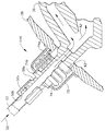
【図2】 本発明の例示的な実施形態によるたわみ継手を備え、それを貫通して延びる供給管を含む、図1に示される軸受ハウジングの一部分の拡大軸方向断面図。
【図3】 本発明の別の実施形態によるたわみ継手を備え、軸受ハウジングを貫通して延びる供給管の、図2と同様な拡大軸方向断面図。
【符号の説明】
10 ターボファンガスタービンエンジン
14 多段軸流圧縮機
18 環状の燃焼器
26 高圧タービンノズル
28 高圧タービン
30 ロータシャフト
32 内側ケーシング
34 軸受ハウジング
36 内側シェル
38 外側シェル
42 半径方向取付フランジ
44 シート部
46 軸受
48 ダンパリング
50 供給管
54 内側シェルのシール手段
56 シェル間プレナム
58 外側シェルのシール手段
60 加圧手段
62 供給開口
64 たわみ継手[0001]
BACKGROUND OF THE INVENTION
The present invention relates generally to gas turbine engines, and more specifically to rotor bearings for gas turbine engines.
[0002]
[Prior art]
In a gas turbine engine, air is pressurized in a compressor and mixed with fuel in a combustor to generate hot combustion gases. The hot gas flows downstream through the turbine stage, which extracts energy from the hot gas. The high pressure turbine is connected to the compressor by a rotor shaft. In an exemplary turbofan gas turbine aircraft engine application, another rotor shaft connects the low pressure turbine to a fan located upstream of the compressor.
[0003]
The two rotor shafts are supported on suitable bearings supported in the corresponding stator frame of the engine. Each bearing has a corresponding bearing housing through which the lubricating oil is appropriately directed during operation.
[0004]
One bearing supporting the high pressure turbine rotor shaft can be installed in the central bore of the engine inside the surrounding annular combustor. In addition, the heat generated by the combustor during operation heats adjacent bearing housings and generates stress (heat-induced stress) induced by heat during operation in the bearing housings. Such thermal stress increases as the temperature difference between hot and cold housing components increases, particularly where adjacent components are constrained to such thermal expansion between them.
[0005]
The bearing housing, in the conventional manner, uses an ambient heat shield between the bearing housing and the hot combustor, and also directs the extracted air from the compressor against heat between the combustor and the bearing housing. It can be protected by forming an air barrier. This increases the complexity of the bearing housing at this location, and in relatively small gas turbine engines, the ability to incorporate such features within the bearing housing is limited by the narrow space available.
[0006]
In one conventional configuration, the bearing housing includes an inner structural shell in which the bearing is mounted, and both axial ends of the inner shell are sealed to the rotor shaft. Various supply pipes or conduits carry lubricating oil to and from the inner shell and at the same time ventilate the inner shell.
[0007]
The inner shell is surrounded by an outer shell, which can be pressurized with air extracted from the compressor to prevent lubricating oil leakage from the inner shell. Also, the air inside the outer shell forms a thermal barrier for the inner shell.
[0008]
Since the supply line needs to extend through the outer shell, a suitable seal is required between it and the outer shell. In one conventional configuration, the supply line is rigidly interconnected with the outer and inner shells to form a suitable solid metal seal therebetween in the local region of the corresponding supply line. can do. However, the outer shell will operate at a higher temperature than the inner shell due to the hot combustion environment surrounding the outer shell. Since the plenum between the shells is pressurized with cooler extraction air, it operates at a correspondingly lower temperature. Also, the oil inside the inner shell remains at a fairly low temperature.
[0009]
Thus, the outer shell thermally expands in both radial and axial directions with respect to the inner shell, resulting in physical constraints between them by local rigid joints in the respective supply lines. Therefore, these joints are subject to thermal stresses during operation, which can be significant for certain engine configurations and can reduce the service life of the bearing housing. There is.
[Patent Document 1]
US Pat. No. 4,9797,872
[Problems to be solved by the invention]
Accordingly, it would be desirable to provide an improved bearing housing that undergoes low thermal stress therein even when heated by a combustor.
[0011]
[Means for Solving the Problems]
The bearing housing includes inner and outer shells through which the rotor shaft can extend. A supply tube is fixedly joined to the inner shell and extends through the supply opening in the outer shell. A flexible joint seal-joins the supply tube to the outer shell at the supply opening so as to allow a temperature movement difference between the inner and outer shells in the supply tube.
[0012]
The invention, together with its further objects and advantages, will be more particularly described in the following detailed description, taken in conjunction with the accompanying drawings, by way of preferred and exemplary embodiments.
[0013]
DETAILED DESCRIPTION OF THE INVENTION
Shown schematically in FIG. 1 is a portion of an exemplary turbofan gas turbine engine that is axisymmetric about a longitudinal or axial
[0014]
A
[0015]
A low pressure turbine (not shown) is located downstream of the high pressure turbine and is disposed upstream of the compressor 14 by another shaft (not shown) mounted within the bore of the high pressure turbine rotor shaft 30 (not shown). (Not shown). This turbofan engine configuration is one example of an engine, where the high pressure
[0016]
Arranged radially inward of the
[0017]
The bearing housing includes a coaxial or concentric
[0018]
The
[0019]
The bearing 46 can have any conventional configuration, such as the roller bearing shown, and can be mounted within the bearing
[0020]
An oil supply pipe or
[0021]
In order to contain the lubricating oil inside the inner shell, suitable means 54 are provided for sealing the inner shell at both axial ends thereof with respect to the
[0022]
Since the bearing
[0023]
The
[0024]
The outer shell includes a front section having a rear end fixedly joined to the inner casing along the conical portion of the mounting
[0025]
Means 58 for sealing the outer shell to the
[0026]
Additional means 60 are provided for pressurizing the
[0027]
The compressor 14 shown in FIG. 1 is disposed upstream of the
[0028]
Accordingly, the interstage extracted air directed through the
[0029]
Thus, a large temperature gradient is created from the
[0030]
In order to absorb the temperature movement difference between the double shells of the bearing housing, the outer shell has a supply opening with a
[0031]
The joint 64 must be flexible to absorb the temperature movement difference between the inner and outer shells at the junction with the
[0032]
An exemplary embodiment of a flexible joint 64 is shown in greater detail in FIG. The fitting includes a tubular bush or
[0033]
The
[0034]
The joint 64 also preferably includes an
[0035]
Correspondingly, an
[0036]
Thus, the
[0037]
The
[0038]
The
[0039]
Thus, when the supply pipe moves within the
[0040]
The
[0041]
In the preferred embodiment shown in FIG. 2, the flexible joint 64 also preferably includes a
[0042]
FIG. 3 shows another embodiment of a flexible joint 64B in which the
[0043]
One end 74a of the bellows is preferably fixedly joined to the
[0044]
Accordingly, the
[0045]
Similar to the embodiment shown in FIG. 2, the embodiment shown in FIG. 3 also includes a
[0046]
Another significant advantage that arises from the structural separation of the two
[0047]
The flexible joint 64 disclosed above does not structurally couple the two shells together, maximizing the concentricity of the bearing
[0048]
The bearing housings disclosed above generally require several oil and ventilation supply lines spaced circumferentially around the circumference of the bearing housing. Also, those supply lines that extend through the outer shell and end at the inner shell preferably use the above-described flexible joints to reduce the heat-induced stress during engine operation.
[0049]
What has been described herein is what is considered to be a preferred and exemplary embodiment of the present invention. Further, the reference numerals described in the claims are for easy understanding, and do not limit the technical scope of the invention to the embodiments.
[Brief description of the drawings]
FIG. 1 is a schematic axial cross-sectional view of a portion of an exemplary turbofan gas turbine engine including a bearing housing according to an exemplary embodiment of the present invention.
2 is an enlarged axial cross-sectional view of a portion of the bearing housing shown in FIG. 1 that includes a supply tube that includes a flexible joint and extends therethrough in accordance with an exemplary embodiment of the present invention.
FIG. 3 is an enlarged axial cross-sectional view similar to FIG. 2, of a supply tube with a flexible joint according to another embodiment of the present invention and extending through the bearing housing.
[Explanation of symbols]
10 turbofan gas turbine engine 14 multistage
Claims (9)
前記たわみ継手(64)は、前記供給開口において前記供給管(50)を取り囲む管状スリーブ(66)を含み、該スリーブの一端(66a)が前記外側シェル(38)にシール接合され、また前記スリーブの反対側他端(66b)が前記供給管にシール接合されており、
前記たわみ継手(64)は、前記供給管(50)を取り囲みかつシール当接した状態で前記スリーブの他端(66b)を受けるための内側シート部(68)と、前記供給開口(62)を取り囲みかつシール当接した状態で前記スリーブ一端(66a)を受けるための外側シート部(70)とを更に含む
ことを特徴とする軸受ハウジング(34)。A central bore (40) for receiving the penetrating rotor shaft (30), a radial mounting flange (42) for mounting to the support casing (32), and a bearing (46) for supporting the shaft are received therein. An inner shell (36) having a seat portion (44) for receiving and a supply pipe (50) fixedly joined to guide the fluid (52), and surrounding and fixed to the inner shell (36) An outer shell (38) that includes a supply opening (62) that receives the supply pipe that is joined and passes therethrough, and allows pressure application of the outer shell and a temperature movement difference between the inner and outer shells in the supply pipe. as such, the flexible coupling seals joining said supply pipe in said supply opening in said outer shell (64), only contains,
The flexible joint (64) includes a tubular sleeve (66) that surrounds the supply tube (50) at the supply opening, one end (66a) of the sleeve being sealed to the outer shell (38), and the sleeve The other end (66b) on the opposite side is sealed to the supply pipe,
The flexible joint (64) includes an inner sheet portion (68) for receiving the other end (66b) of the sleeve in a state of surrounding the supply pipe (50) and being in sealing contact, and the supply opening (62). A bearing housing (34) , further comprising an outer seat portion (70) for receiving said sleeve end (66a) in a surrounding and sealing contact .
前記外側シート部(70)は、前記供給開口(62)及び前記供給管(50)の周りで前記外側シェル(38)に固定接合され、該供給管から半径方向外方に間隔を置いて配置されて、前記スリーブの一端(66a)を滑り嵌め状態で軸方向に受ける管状キャップを含む、
ことを特徴とする、請求項2に記載のハウジング。The inner sheet portion (68) is fixedly joined to the supply pipe (50), and a part of the inner sheet section (68) is radially spaced from the supply pipe to slide the other end (66b) of the sleeve. Including a retaining ring that is received in the axial direction in the fitted state,
The outer sheet portion (70) is fixedly joined to the outer shell (38) around the supply opening (62) and the supply pipe (50), and is spaced radially outward from the supply pipe. And including a tubular cap for receiving one end (66a) of the sleeve in an axial direction in a sliding fit.
The housing according to claim 2, wherein:
前記外側シェル(38)を前記シャフトに対してシールするための手段(58)と、
前記内側シェル(36)内部のオイル(52)をシールするために前記外側シェル(38)を加圧するための手段(60)と、
を更に含むことを特徴とする、請求項1に記載のハウジング。Means (54) for sealing the inner shell (36) to the shaft (30);
Means (58) for sealing the outer shell (38) to the shaft;
Means (60) for pressurizing the outer shell (38) to seal the oil (52) inside the inner shell (36);
The housing according to claim 1 , further comprising:
前記加圧手段は、空気(16)を加圧するための圧縮機(14)と加圧された空気を前記外側シェル(38)内部に導くための抽気管路(60)とを含み、
前記圧縮機は、前記支持ケーシング(32)を取り囲む燃焼器(18)の上流に配置され、運転中に、加圧された空気を該燃焼器に導き該燃焼器中で燃料と混合して、高温の燃焼ガス(24)を発生させるように作動し、
該高温の燃焼ガスが前記軸受ハウジング(34)に加熱を生じる、
こと特徴とする、請求項4に記載のハウジング。 The support casing (32) surrounds the outer shell (38) and is fixedly joined to the inner shell (36) at the mounting flange (42) of the inner shell;
The pressurizing means includes a compressor (14) for pressurizing air (16) and a bleed line (60) for guiding the pressurized air into the outer shell (38),
The compressor is located upstream of the combustor (18) surrounding the support casing (32) and, during operation, directs pressurized air to the combustor and mixes it with fuel in the combustor; Operates to generate hot combustion gases (24);
The hot combustion gases cause heating in the bearing housing (34);
The housing according to claim 4, wherein
該内側シェル(36)に固定接合され、前記外側シェル(38)内の供給開口(62)を貫通して延びる供給管(50)と、
該供給管における前記内側及び外側シェル間のムーブメント差を可能にするように、前記供給開口において前記供給管(50)を前記外側シェルにシール接合するたわみ継手(64)と、
を含み、
前記たわみ継手(64)は、前記供給開口において前記供給管(50)を取り囲む管状スリーブ(66)と、前記供給管を取り囲みかつシール当接した状態で前記スリーブの一端を受けるための内側シート部(68)と、前記供給開口を取り囲みかつシール当接した状態で前記スリーブの反対側端を受けるための外側シート部(70)と、
を含むことを特徴とする軸受ハウジング(34)。Coaxially disposed inner and outer shells (36, 38);
A supply pipe (50) fixedly joined to the inner shell (36) and extending through a supply opening (62) in the outer shell (38);
A flexible joint (64) sealingly connecting the supply pipe (50) to the outer shell at the supply opening to allow a movement difference between the inner and outer shells in the supply pipe;
Only including,
The flexible joint (64) includes a tubular sleeve (66) surrounding the supply pipe (50) in the supply opening, and an inner sheet portion for receiving one end of the sleeve in a state of surrounding the supply pipe and in sealing contact with the tubular sleeve (66). (68), and an outer sheet portion (70) for receiving the opposite end of the sleeve in a state of surrounding the supply opening and in sealing contact,
A bearing housing (34) characterized by comprising:
前記内側シート部(68)は、前記供給管(50)に固定接合された保持リングを含み、
前記外側シート部(70)は、前記供給開口の周りで前記外側シェルに固定接合された管状キャップを含む、ことを特徴とする、請求項6に記載のハウジング。 The sleeve (66) is substantially linear between the ends of the sleeve;
The inner sheet portion (68) includes a retaining ring fixedly joined to the supply pipe (50),
A housing according to claim 6, characterized in that the outer sheet part (70) comprises a tubular cap fixedly joined to the outer shell around the supply opening.
該内側シェル(36)に固定接合され、前記外側シェル(38)内の供給開口(62)を貫通して延びる供給管(50)と、
該供給管における前記内側及び外側シェル間のムーブメント差を可能にするように、前記供給開口において前記供給管(50)を前記外側シェルにシール接合するたわみ継手(64)と、
を含み、
前記たわみ継手(64B)は、前記供給開口(62)において前記供給管(50)を取り囲み、前記供給管と前記供給開口の周りの前記外側シェルとに固定接合された対向する端部(74a、b)を有する管状ベローズ(74)を含むことを特徴とする、軸受ハウジング(34)。 Coaxially disposed inner and outer shells (36, 38);
A supply pipe (50) fixedly joined to the inner shell (36) and extending through a supply opening (62) in the outer shell (38);
A flexible joint (64) sealingly connecting the supply pipe (50) to the outer shell at the supply opening to allow a movement difference between the inner and outer shells in the supply pipe;
Including
The flexible joint (64B) surrounds the supply pipe (50) at the supply opening (62) and is opposed to the supply pipe and the outer shell around the supply opening. Bearing housing (34) , characterized in that it comprises a tubular bellows (74) with b).
Applications Claiming Priority (2)
| Application Number | Priority Date | Filing Date | Title |
|---|---|---|---|
| US10/024,696 US6679045B2 (en) | 2001-12-18 | 2001-12-18 | Flexibly coupled dual shell bearing housing |
| US10/024696 | 2001-12-18 |
Publications (3)
| Publication Number | Publication Date |
|---|---|
| JP2003227309A JP2003227309A (en) | 2003-08-15 |
| JP2003227309A5 JP2003227309A5 (en) | 2006-02-02 |
| JP4256151B2 true JP4256151B2 (en) | 2009-04-22 |
Family
ID=21821914
Family Applications (1)
| Application Number | Title | Priority Date | Filing Date |
|---|---|---|---|
| JP2002364514A Expired - Fee Related JP4256151B2 (en) | 2001-12-18 | 2002-12-17 | Flexible combined double shell bearing housing |
Country Status (5)
| Country | Link |
|---|---|
| US (1) | US6679045B2 (en) |
| EP (1) | EP1331364B1 (en) |
| JP (1) | JP4256151B2 (en) |
| CN (1) | CN100429384C (en) |
| DE (1) | DE60220370T2 (en) |
Families Citing this family (64)
| Publication number | Priority date | Publication date | Assignee | Title |
|---|---|---|---|---|
| US6691019B2 (en) * | 2001-12-21 | 2004-02-10 | General Electric Company | Method and system for controlling distortion of turbine case due to thermal variations |
| US7174997B2 (en) * | 2003-07-03 | 2007-02-13 | United Technologies Corporation | Failure tolerant passive lubrication system |
| DE602004014154D1 (en) * | 2003-07-29 | 2008-07-10 | Pratt & Whitney Canada | Turbofan engine casing, turbofan engine and corresponding process |
| US7370467B2 (en) | 2003-07-29 | 2008-05-13 | Pratt & Whitney Canada Corp. | Turbofan case and method of making |
| US7387189B2 (en) * | 2003-08-14 | 2008-06-17 | United Technologies Corp. | Emergency lubrication system |
| US7093418B2 (en) * | 2004-04-21 | 2006-08-22 | Honeywell International, Inc. | Gas turbine engine including a low pressure sump seal buffer source and thermally isolated sump |
| US7458202B2 (en) * | 2004-10-29 | 2008-12-02 | General Electric Company | Lubrication system for a counter-rotating turbine engine and method of assembling same |
| US7287384B2 (en) * | 2004-12-13 | 2007-10-30 | Pratt & Whitney Canada Corp. | Bearing chamber pressurization system |
| US7451541B2 (en) * | 2005-02-04 | 2008-11-18 | Pratt & Whitney Canada Corp. | Method of heat shielding an inner tube |
| US8065022B2 (en) * | 2005-09-06 | 2011-11-22 | General Electric Company | Methods and systems for neural network modeling of turbine components |
| US8205426B2 (en) * | 2006-07-31 | 2012-06-26 | General Electric Company | Method and apparatus for operating gas turbine engines |
| DE102007061995B4 (en) * | 2007-12-21 | 2012-03-01 | Airbus Operations Gmbh | Device for the mechanically decoupled attachment of an aircraft component through which hot gas flows |
| US8342796B2 (en) * | 2008-04-29 | 2013-01-01 | Honeywell International Inc. | Damping systems for use in engines |
| US8182156B2 (en) * | 2008-07-31 | 2012-05-22 | General Electric Company | Nested bearing cages |
| US8092161B2 (en) * | 2008-09-24 | 2012-01-10 | Siemens Energy, Inc. | Thermal shield at casing joint |
| US8793991B2 (en) * | 2009-12-03 | 2014-08-05 | General Electric Company | Displacer and superconducting magnet |
| FR2956695B1 (en) * | 2010-02-25 | 2012-11-16 | Turbomeca | REAR REAR BEARING SUPPORT WITH STOPPER FOR TURBOMACHINE |
| US20120011824A1 (en) * | 2010-07-16 | 2012-01-19 | United Technologies Corporation | Integral lubrication tube and nozzle combination |
| US9234431B2 (en) * | 2010-07-20 | 2016-01-12 | Siemens Energy, Inc. | Seal assembly for controlling fluid flow |
| EP2431574A1 (en) * | 2010-09-20 | 2012-03-21 | Siemens Aktiengesellschaft | Gas turbine and method for operating a gas turbine |
| US8777158B2 (en) * | 2011-03-25 | 2014-07-15 | The Boeing Company | Joint sealing system |
| RU2459966C1 (en) * | 2011-04-06 | 2012-08-27 | Открытое акционерное общество "Авиадвигатель" | Gas turbine engine support |
| US8770924B2 (en) | 2011-07-07 | 2014-07-08 | Siemens Energy, Inc. | Gas turbine engine with angled and radial supports |
| US8727632B2 (en) | 2011-11-01 | 2014-05-20 | General Electric Company | Bearing support apparatus for a gas turbine engine |
| CN102425639A (en) * | 2011-11-30 | 2012-04-25 | 中国航空动力机械研究所 | elastic support structure |
| US10001028B2 (en) | 2012-04-23 | 2018-06-19 | General Electric Company | Dual spring bearing support housing |
| US9353647B2 (en) * | 2012-04-27 | 2016-05-31 | General Electric Company | Wide discourager tooth |
| US9567908B2 (en) * | 2012-04-27 | 2017-02-14 | General Electric Company | Mitigating vortex pumping effect upstream of oil seal |
| EP2672071A1 (en) * | 2012-06-08 | 2013-12-11 | Siemens Aktiengesellschaft | Drain pipe arrangement and gas turbine engine comprising a drain pipe arrangement |
| US20140010648A1 (en) * | 2012-06-29 | 2014-01-09 | United Technologies Corporation | Sleeve for turbine bearing stack |
| EP2722495B1 (en) * | 2012-10-17 | 2015-03-11 | ABB Turbo Systems AG | Gas entry housing and corresponding exhaust gas turbine |
| EP3044437B1 (en) * | 2013-09-09 | 2018-10-31 | United Technologies Corporation | Turbine engine bearing support comprising a decoupler |
| FR3011880B1 (en) * | 2013-10-10 | 2015-10-23 | Snecma | DEVICE FOR TRANSFERRING OIL BETWEEN TWO REFERENTIALS IN ROTATION IN RELATION TO EACH OTHER, AND AIRCRAFT TURBOMACHINE FOR AIRCRAFT WITH SUCH A DEVICE |
| RU2560655C1 (en) * | 2014-06-02 | 2015-08-20 | Российская Федерация, от имени которой выступает Министерство промышленности и торговли Российской Федерации (Минпромторг России) | Gas turbine engine support |
| US9856741B2 (en) * | 2014-10-13 | 2018-01-02 | Pw Power Systems, Inc. | Power turbine cooling air metering ring |
| FR3030615B1 (en) * | 2014-12-19 | 2017-02-10 | Snecma | ASSEMBLY FOR TURBOMACHINE, COMPRISING A SEAL AND A SEAL SUPPORT RING |
| FR3036441B1 (en) * | 2015-05-22 | 2019-06-07 | Safran Aircraft Engines | CAPOTE OIL SPRINKLER |
| US9714584B2 (en) | 2015-06-18 | 2017-07-25 | United Technologies Corporation | Bearing support damping |
| CA2934668C (en) | 2015-07-09 | 2018-11-06 | General Electric Company | Bearing assembly for supporting a rotor shaft of a gas turbine engine |
| KR102010445B1 (en) * | 2015-08-19 | 2019-08-13 | 다이도 메탈 고교 가부시키가이샤 | Vertical bearing device |
| FR3041686B1 (en) * | 2015-09-30 | 2018-08-31 | Safran Aircraft Engines | DEVICE FOR SUPPORTING A PIPING IN A TURBOMACHINE |
| CN105736147B (en) * | 2016-01-29 | 2017-08-25 | 中国科学院工程热物理研究所 | A kind of motor oil oil supply structure and the gas-turbine unit with the structure |
| US10577973B2 (en) * | 2016-02-18 | 2020-03-03 | General Electric Company | Service tube for a turbine engine |
| US10113483B2 (en) * | 2016-02-23 | 2018-10-30 | General Electric Company | Sump housing for a gas turbine engine |
| US10358942B2 (en) * | 2016-02-25 | 2019-07-23 | General Electric Company | Core differential bearing with centering spring and squeeze film damper |
| US10001166B2 (en) | 2016-04-18 | 2018-06-19 | General Electric Company | Gas distribution labyrinth for bearing pad |
| US10036279B2 (en) | 2016-04-18 | 2018-07-31 | General Electric Company | Thrust bearing |
| US10914195B2 (en) | 2016-04-18 | 2021-02-09 | General Electric Company | Rotary machine with gas bearings |
| US10066505B2 (en) | 2016-04-18 | 2018-09-04 | General Electric Company | Fluid-filled damper for gas bearing assembly |
| US9746029B1 (en) | 2016-04-18 | 2017-08-29 | General Electric Company | Bearing |
| US9951811B2 (en) | 2016-04-18 | 2018-04-24 | General Electric Company | Bearing |
| US11193385B2 (en) | 2016-04-18 | 2021-12-07 | General Electric Company | Gas bearing seal |
| ITUA20162733A1 (en) * | 2016-04-20 | 2017-10-20 | Ge Avio Srl | OIL TRANSFER UNIT TO TRANSFER OIL BETWEEN A STATIC PART AND A ROTATING PART |
| US10221766B2 (en) * | 2016-04-29 | 2019-03-05 | General Electric Company | Sump assembly for a gas turbine engine |
| US10823061B2 (en) * | 2016-07-15 | 2020-11-03 | General Electric Company | Engine air inlet having a double-panel heated wall |
| US20200025038A1 (en) * | 2018-07-17 | 2020-01-23 | United Technologies Corporation | Sealing configuration to reduce air leakage |
| US10830077B2 (en) * | 2018-07-17 | 2020-11-10 | Raytheon Technologies Corporation | Sealing configuration to reduce air leakage |
| US10781710B2 (en) * | 2018-07-17 | 2020-09-22 | Raytheon Technologies Corporation | Sealing configuration to reduce air leakage |
| US11199103B2 (en) * | 2018-09-06 | 2021-12-14 | General Electric Company | Seal assembly for a turbomachine |
| CN110005545B (en) * | 2019-02-21 | 2020-08-18 | 西安航天动力研究所 | Squirrel-cage elastic supporting bearing cavity structure |
| US10844745B2 (en) | 2019-03-29 | 2020-11-24 | Pratt & Whitney Canada Corp. | Bearing assembly |
| US10808573B1 (en) | 2019-03-29 | 2020-10-20 | Pratt & Whitney Canada Corp. | Bearing housing with flexible joint |
| FR3096725B1 (en) * | 2019-05-29 | 2021-05-14 | Safran Helicopter Engines | AIRCRAFT TURBOMACHINE MODULE |
| US11492926B2 (en) | 2020-12-17 | 2022-11-08 | Pratt & Whitney Canada Corp. | Bearing housing with slip joint |
Family Cites Families (8)
| Publication number | Priority date | Publication date | Assignee | Title |
|---|---|---|---|---|
| GB595346A (en) * | 1941-05-07 | 1947-12-03 | Hayne Constant | Improvements relating to bearings of internal combustion gas turbines, turbine type gas compressors, and like high speed machinery |
| GB582082A (en) * | 1941-05-07 | 1946-11-05 | Henry Lewis Guy | Improvements in pipe connections to enclosed members |
| GB961522A (en) | 1963-01-09 | 1964-06-24 | Rolls Royce | Bearing assembly |
| US4076452A (en) * | 1974-04-09 | 1978-02-28 | Brown, Boveri-Sulzer Turbomaschinen Ag | Gas turbine plant |
| US4478551A (en) | 1981-12-08 | 1984-10-23 | United Technologies Corporation | Turbine exhaust case design |
| US4979872A (en) | 1989-06-22 | 1990-12-25 | United Technologies Corporation | Bearing compartment support |
| DE4227280C1 (en) * | 1992-08-18 | 1993-08-05 | Siemens Ag, 8000 Muenchen, De | |
| EP0801217B1 (en) * | 1996-03-13 | 2002-06-19 | Technical Directions Inc. | Turbine engine |
-
2001
- 2001-12-18 US US10/024,696 patent/US6679045B2/en not_active Expired - Lifetime
-
2002
- 2002-12-17 JP JP2002364514A patent/JP4256151B2/en not_active Expired - Fee Related
- 2002-12-18 EP EP02258701A patent/EP1331364B1/en not_active Expired - Lifetime
- 2002-12-18 CN CNB021563667A patent/CN100429384C/en not_active Expired - Fee Related
- 2002-12-18 DE DE60220370T patent/DE60220370T2/en not_active Expired - Lifetime
Also Published As
| Publication number | Publication date |
|---|---|
| US20030110778A1 (en) | 2003-06-19 |
| CN100429384C (en) | 2008-10-29 |
| DE60220370T2 (en) | 2008-01-24 |
| DE60220370D1 (en) | 2007-07-12 |
| JP2003227309A (en) | 2003-08-15 |
| CN1427140A (en) | 2003-07-02 |
| EP1331364B1 (en) | 2007-05-30 |
| EP1331364A3 (en) | 2005-01-05 |
| US6679045B2 (en) | 2004-01-20 |
| EP1331364A2 (en) | 2003-07-30 |
Similar Documents
| Publication | Publication Date | Title |
|---|---|---|
| JP4256151B2 (en) | Flexible combined double shell bearing housing | |
| EP2938863B1 (en) | Mechanical linkage for segmented heat shield | |
| US8157509B2 (en) | Method, system and apparatus for turbine diffuser sealing | |
| JP6165928B2 (en) | Igniter assembly for a gas turbine engine | |
| EP0244342B1 (en) | Sliding joint for an annular combustor | |
| JP4097994B2 (en) | Joint for two-part CMC combustion chamber | |
| GB2234299A (en) | Support arrangement for nozzle guide vane | |
| CN115949968B (en) | Combustor swirler to pseudo-dome attachment and interface with CMC dome | |
| US11105222B1 (en) | Integrated thermal protection for an exhaust case assembly | |
| EP3885593B1 (en) | Bearing housing oil intake to supply dual bearing structure | |
| JP5451314B2 (en) | Fuel nozzle assembly for use in a gas turbine engine and assembly method thereof. | |
| RU2666828C2 (en) | Heat-shield manifold system for midframe case of gas turbine engine | |
| CN107091160A (en) | Maintenance tubes for turbo engines | |
| EP2622278B1 (en) | Gas turbine assembly and method therefor | |
| EP4007843A1 (en) | Seal assembly | |
| US11988106B2 (en) | Heat-protection element for a bearing chamber of a gas turbine | |
| JP2006329425A (en) | Expansion joint and method of assembling it | |
| US9488105B2 (en) | Gas turbine assembly and method therefor | |
| JP2002129983A (en) | Gas turbine combustor scroll seal device | |
| JPH06213003A (en) | Gas turbine engine |
Legal Events
| Date | Code | Title | Description |
|---|---|---|---|
| A521 | Request for written amendment filed |
Free format text: JAPANESE INTERMEDIATE CODE: A523 Effective date: 20051213 |
|
| A621 | Written request for application examination |
Free format text: JAPANESE INTERMEDIATE CODE: A621 Effective date: 20051213 |
|
| A131 | Notification of reasons for refusal |
Free format text: JAPANESE INTERMEDIATE CODE: A131 Effective date: 20080422 |
|
| A521 | Request for written amendment filed |
Free format text: JAPANESE INTERMEDIATE CODE: A523 Effective date: 20080718 |
|
| A131 | Notification of reasons for refusal |
Free format text: JAPANESE INTERMEDIATE CODE: A131 Effective date: 20080916 |
|
| A521 | Request for written amendment filed |
Free format text: JAPANESE INTERMEDIATE CODE: A523 Effective date: 20081007 |
|
| TRDD | Decision of grant or rejection written | ||
| A01 | Written decision to grant a patent or to grant a registration (utility model) |
Free format text: JAPANESE INTERMEDIATE CODE: A01 Effective date: 20090106 |
|
| A01 | Written decision to grant a patent or to grant a registration (utility model) |
Free format text: JAPANESE INTERMEDIATE CODE: A01 |
|
| A61 | First payment of annual fees (during grant procedure) |
Free format text: JAPANESE INTERMEDIATE CODE: A61 Effective date: 20090129 |
|
| FPAY | Renewal fee payment (event date is renewal date of database) |
Free format text: PAYMENT UNTIL: 20120206 Year of fee payment: 3 |
|
| R150 | Certificate of patent or registration of utility model |
Free format text: JAPANESE INTERMEDIATE CODE: R150 |
|
| FPAY | Renewal fee payment (event date is renewal date of database) |
Free format text: PAYMENT UNTIL: 20130206 Year of fee payment: 4 |
|
| FPAY | Renewal fee payment (event date is renewal date of database) |
Free format text: PAYMENT UNTIL: 20140206 Year of fee payment: 5 |
|
| R250 | Receipt of annual fees |
Free format text: JAPANESE INTERMEDIATE CODE: R250 |
|
| R250 | Receipt of annual fees |
Free format text: JAPANESE INTERMEDIATE CODE: R250 |
|
| R250 | Receipt of annual fees |
Free format text: JAPANESE INTERMEDIATE CODE: R250 |
|
| R250 | Receipt of annual fees |
Free format text: JAPANESE INTERMEDIATE CODE: R250 |
|
| LAPS | Cancellation because of no payment of annual fees |