JP4257640B2 - Tool steel manufacturing method - Google Patents
Tool steel manufacturing method Download PDFInfo
- Publication number
- JP4257640B2 JP4257640B2 JP2003133883A JP2003133883A JP4257640B2 JP 4257640 B2 JP4257640 B2 JP 4257640B2 JP 2003133883 A JP2003133883 A JP 2003133883A JP 2003133883 A JP2003133883 A JP 2003133883A JP 4257640 B2 JP4257640 B2 JP 4257640B2
- Authority
- JP
- Japan
- Prior art keywords
- tool steel
- less
- strength
- toughness
- mass
- Prior art date
- Legal status (The legal status is an assumption and is not a legal conclusion. Google has not performed a legal analysis and makes no representation as to the accuracy of the status listed.)
- Expired - Fee Related
Links
- 229910001315 Tool steel Inorganic materials 0.000 claims description 59
- 238000004519 manufacturing process Methods 0.000 claims description 24
- 238000005496 tempering Methods 0.000 claims description 13
- 229910052750 molybdenum Inorganic materials 0.000 claims description 12
- 229910052721 tungsten Inorganic materials 0.000 claims description 11
- 238000010791 quenching Methods 0.000 claims description 9
- 230000000171 quenching effect Effects 0.000 claims description 9
- 229910052804 chromium Inorganic materials 0.000 claims description 5
- 239000012535 impurity Substances 0.000 claims description 4
- 229910052748 manganese Inorganic materials 0.000 claims description 4
- 229910052782 aluminium Inorganic materials 0.000 claims description 3
- 229910052797 bismuth Inorganic materials 0.000 claims description 3
- -1 by mass% Inorganic materials 0.000 claims description 3
- 229910052745 lead Inorganic materials 0.000 claims description 3
- 229910052758 niobium Inorganic materials 0.000 claims description 2
- 239000000463 material Substances 0.000 description 42
- 238000012360 testing method Methods 0.000 description 20
- 238000010438 heat treatment Methods 0.000 description 19
- 239000000523 sample Substances 0.000 description 19
- 230000000694 effects Effects 0.000 description 17
- 239000002245 particle Substances 0.000 description 10
- 230000015572 biosynthetic process Effects 0.000 description 9
- 238000005728 strengthening Methods 0.000 description 9
- XEEYBQQBJWHFJM-UHFFFAOYSA-N Iron Chemical group [Fe] XEEYBQQBJWHFJM-UHFFFAOYSA-N 0.000 description 8
- 238000000034 method Methods 0.000 description 8
- 229910000831 Steel Inorganic materials 0.000 description 7
- 238000001816 cooling Methods 0.000 description 7
- 230000007423 decrease Effects 0.000 description 7
- 239000010959 steel Substances 0.000 description 7
- 239000006185 dispersion Substances 0.000 description 6
- 238000000635 electron micrograph Methods 0.000 description 6
- 239000000203 mixture Substances 0.000 description 6
- 229910045601 alloy Inorganic materials 0.000 description 5
- 239000000956 alloy Substances 0.000 description 5
- 150000001247 metal acetylides Chemical class 0.000 description 5
- 238000002474 experimental method Methods 0.000 description 4
- 230000006698 induction Effects 0.000 description 4
- 238000002844 melting Methods 0.000 description 4
- 230000008018 melting Effects 0.000 description 4
- 229910017116 Fe—Mo Inorganic materials 0.000 description 3
- 229910002056 binary alloy Inorganic materials 0.000 description 3
- 238000011156 evaluation Methods 0.000 description 3
- 230000001965 increasing effect Effects 0.000 description 3
- 229910052742 iron Inorganic materials 0.000 description 3
- 239000011159 matrix material Substances 0.000 description 3
- 229910052751 metal Inorganic materials 0.000 description 3
- 238000005498 polishing Methods 0.000 description 3
- 230000008569 process Effects 0.000 description 3
- 229910052761 rare earth metal Inorganic materials 0.000 description 3
- 229910052719 titanium Inorganic materials 0.000 description 3
- 229910052720 vanadium Inorganic materials 0.000 description 3
- 230000005540 biological transmission Effects 0.000 description 2
- 238000010894 electron beam technology Methods 0.000 description 2
- 229910000765 intermetallic Inorganic materials 0.000 description 2
- 230000007246 mechanism Effects 0.000 description 2
- 239000002184 metal Substances 0.000 description 2
- 150000004767 nitrides Chemical class 0.000 description 2
- 238000001556 precipitation Methods 0.000 description 2
- 238000012545 processing Methods 0.000 description 2
- 239000006104 solid solution Substances 0.000 description 2
- 238000001330 spinodal decomposition reaction Methods 0.000 description 2
- 238000000992 sputter etching Methods 0.000 description 2
- 229910052715 tantalum Inorganic materials 0.000 description 2
- 238000011282 treatment Methods 0.000 description 2
- 229910052726 zirconium Inorganic materials 0.000 description 2
- 229910000838 Al alloy Inorganic materials 0.000 description 1
- 239000002970 Calcium lactobionate Substances 0.000 description 1
- RYGMFSIKBFXOCR-UHFFFAOYSA-N Copper Chemical compound [Cu] RYGMFSIKBFXOCR-UHFFFAOYSA-N 0.000 description 1
- 229910018565 CuAl Inorganic materials 0.000 description 1
- 229910000997 High-speed steel Inorganic materials 0.000 description 1
- 229910018100 Ni-Sn Inorganic materials 0.000 description 1
- 229910000943 NiAl Inorganic materials 0.000 description 1
- 229910018532 Ni—Sn Inorganic materials 0.000 description 1
- 230000001133 acceleration Effects 0.000 description 1
- 230000009471 action Effects 0.000 description 1
- 238000005054 agglomeration Methods 0.000 description 1
- 230000002776 aggregation Effects 0.000 description 1
- 230000032683 aging Effects 0.000 description 1
- 238000004458 analytical method Methods 0.000 description 1
- 238000000137 annealing Methods 0.000 description 1
- TZCXTZWJZNENPQ-UHFFFAOYSA-L barium sulfate Chemical compound [Ba+2].[O-]S([O-])(=O)=O TZCXTZWJZNENPQ-UHFFFAOYSA-L 0.000 description 1
- 230000008859 change Effects 0.000 description 1
- 229910052802 copper Inorganic materials 0.000 description 1
- 239000010949 copper Substances 0.000 description 1
- 239000013078 crystal Substances 0.000 description 1
- 238000002050 diffraction method Methods 0.000 description 1
- 238000007598 dipping method Methods 0.000 description 1
- 238000002003 electron diffraction Methods 0.000 description 1
- 238000005516 engineering process Methods 0.000 description 1
- 230000002708 enhancing effect Effects 0.000 description 1
- 238000000556 factor analysis Methods 0.000 description 1
- 238000007656 fracture toughness test Methods 0.000 description 1
- 238000009863 impact test Methods 0.000 description 1
- 238000003754 machining Methods 0.000 description 1
- 229910000734 martensite Inorganic materials 0.000 description 1
- 238000005259 measurement Methods 0.000 description 1
- 239000002086 nanomaterial Substances 0.000 description 1
- 238000002360 preparation method Methods 0.000 description 1
- 230000005855 radiation Effects 0.000 description 1
- 150000002910 rare earth metals Chemical class 0.000 description 1
- 239000002994 raw material Substances 0.000 description 1
- 238000007670 refining Methods 0.000 description 1
- 238000011160 research Methods 0.000 description 1
- 230000000630 rising effect Effects 0.000 description 1
- 239000010935 stainless steel Substances 0.000 description 1
- 229910001220 stainless steel Inorganic materials 0.000 description 1
- 238000012916 structural analysis Methods 0.000 description 1
- 238000006467 substitution reaction Methods 0.000 description 1
- 238000009864 tensile test Methods 0.000 description 1
- 230000009466 transformation Effects 0.000 description 1
- 238000000844 transformation Methods 0.000 description 1
Images


Landscapes
- Heat Treatment Of Articles (AREA)
Description
【0001】
【発明の属する技術分野】
本発明は、工具鋼の組織の変調構造を構成するMoやWの濃度ゆらぎを調整することで、強度や靭性といった機械的性質を改善するための工具鋼の製造方法に関するものである。
【0002】
【従来の技術】
従来、高強度材料は様々な強化メカニズムを組み合わせて高強度化を達成している。特に、汎用の高強度材料の場合、機械加工が効率良く行えかつ使用時には高強度を容易に得ることが重要である。そのため、焼鈍状態では低硬度で加工し易く、その後の焼入れ、時効処理や焼戻し処理によって高強度化できる粒子分散強化が広く利用されている。その分散粒子は多種・多様で、例えば、高速度鋼では異なる種類の炭化物、析出硬化ステンレス鋼ではη−Ni3Tiあるいはβ−NiAl等の金属間化合物、銅基合金ではγ−BeCu、アルミニウム合金ではθ−CuAl2等の金属間化合物である。
【0003】
これら材料の降伏強度の増加分は、分散粒子の大きさ、体積率や整合性等を評価することによって見積ることができる(例えば、非特許文献1参照)。一方、靭性は第二相粒子(分散粒子)の体積率が極力少ない方が優れる。つまり、粒子分散強化を利用した高強度材料は、上述した要因を評価することによって、要求特性を満足するように強度と靭性をバランスさせて工業製品として提供されている。
【0004】
また、粒子分散強化と異なる高強度化機構として、スピノーダル分解によって形成した変調構造を利用した高強度材料が提案されている。例えば、研究例は少ないが、Fe−Mo2元系合金やIC素子などのリードフレーム材として考えられているCu−Ni−Sn合金等がある。鉄基材料であるFe−Mo2元系合金の場合、スピノーダル分解によって変調構造を形成してビッカース硬度1100にも達する高硬度を示すことが報告されている(例えば、非特許文献2,3参照)。
【0005】
【非特許文献1】
「金属便覧」改訂6版 日本金属学会編 丸善(株)(2000),p.318
【0006】
【非特許文献2】
「金属」vol.67 No.5(1997),p.395
【0007】
【非特許文献3】
「Proc of inter Symposium on Phase Transformations During Thermal Mechanical Processing of Steel.」 ed. By E.B.Hawbolt and S.Yue. (1995),p.473
【0008】
【発明が解決しようとする課題】
ところが、これまでは、工具鋼のような粒子分散強化で高強度化した材料で上述した要因解析を行っても説明できない機械的性質の差異が発生する場合もあり、なかでもMoをある程度多く含有する材料で低靭性となる問題があった。特に、最近の市場動向が軽量化および長寿命化の傾向であるため素形材料の高強度化が要求されるようになり、上記の問題が顕著となってきた。この問題は、安定した品質を保証すべき工業製品を効率良く提供する上で大きな課題となる。また、これまでの問題解消対策は、この原因が不明であったため再度焼鈍、焼入れ・焼戻し等の熱処理を施しており、多大な工数を要していた。
【0009】
一方、Fe−Mo2元系合金では変調構造を形成するために高価なMoを20質量%以上も含有する必要があり、また高硬度は得られるものの非常に脆く実用に適さない。ある程度の靭性改善はCo,V元素を添加すれば可能であるが、やはり高価なCoを約40質量%も添加する必要があり、素形材である工具鋼等への適用はコストの問題があるため非常に困難である。
【0010】
本発明の目的は、工具鋼のような粒子分散強化で高強度化していると考えられていた材料で、市場ニーズに合わせて高強度化、高靭性化、さらに強度−靭性の均衡化を達成し安定した品質の工業製品を効率良く提供するため、工具鋼での機械的性質に及ぼす組織要因を明確にして機械的性質を改善するための製造方法を提供することである。
【0011】
【課題を解決するための手段】
本発明者は、既存の材料を用いて詳細なナノ組織解析を行い機械的性質に及ぼす組織の影響について鋭意研究した。その結果、Moをあまり含有していない工具鋼でも変調構造が形成されていることを見出し、これが強度−靭性バランスに多大な影響を及ぼすことも明らかにした。また、変調構造は、微量添加元素や熱処理条件によっても種々変化し、強度−靭性バランスが顕著に変化することも明らかにした。このことより、変調構造の形成を制御することによって強度−靭性バランスを自由に調整できることを見いだし、特に各種工具に適用される工具鋼の具体的な用途の妥当性までをも提案できる工具鋼の製造方法として、本発明に到達した。
【0012】
すなわち本発明は、質量%で、C:0.1〜3.0%、Si:3.0%以下、Mn:2.0%以下、Cr:0〜18.0%、MoおよびWの1種または2種を(Mo+0.5W)で0.1〜16.0%、V:6.0%以下含有し、残部Feおよび不可避的不純物からなる工具鋼の製造方法であって、
MoおよびWの含有量および/または焼入れ後の300〜700℃の範囲での焼戻しの条件を調整して、工具鋼の組織の変調構造を制御することにより、強度と靱性のバランスを調整することを特徴とする工具鋼の製造方法である。または、質量%で、Cおよび/またはNを合計で0.1〜3.0%、Si:3.0%以下、Mn:2.0%以下、Cr:0〜18.0%、MoおよびWの1種または2種を(Mo+0.5W)で0.1〜16.0%、V:6.0%以下含有し、残部Feおよび不可避的不純物からなる工具鋼の製造方法であって、
MoおよびWの含有量および/または焼入れ後の300〜700℃の範囲での焼戻しの条件を調整して、工具鋼の組織の変調構造を制御することにより、強度と靱性のバランスを調整することを特徴とする工具鋼の製造方法である。
【0013】
そして、本発明の工具鋼の製造方法は、例えばその工具鋼が、質量%で、Ni:3.0%以下、Co:15.0%以下、Al:0.1%以下の群から選ばれた1種または2種以上を含有するものであれば、特に工具鋼としての強度と靭性のバランスを改善する手法として効果を発揮する。あるいはさらに、その工具鋼が、質量%で、S:0.20%以下、Ca:0.050%以下、Pb:0.2%以下、Bi:0.2%以下、B:0.010%以下、Nb:0.05%以下、Ti:0.05%以下、Ta:0.05%以下、Zr:0.05%以下、希土類金属元素:各々0.50%以下の1種または2種以上の元素を含有してもよい。そして、上記の工具鋼で、組織の変調構造の形成を制御することによって、市場ニーズに合わせて、高強度化もしくは高靭性化、さらには強度−靭性バランスを向上できる有効な製造方法である。
【0014】
【発明の実施の形態】
上述したように、本発明の重要な特徴は、機械的性質、具体的には強度と靭性のバランスを改善するための方法として工具鋼の組織の変調構造の形成を制御することを採用したことにある。そして、特に各種工具に適用される工具鋼を対象にして、その適用される具体的な用途の妥当性までをも提案できる製造方法として、確立したことにある。
【0015】
最初に本発明の根幹をなす工具鋼の組織の変調構造を制御するための、その観察する方法について説明する。工具鋼の組織は、透過型電子顕微鏡を用いて観察する。本発明での具体的な評価は、試料作製を電解研磨もしくはイオンミリングで行い、加速電圧:200kV、倍率:〜40万で、電子線回折(制限視野回折法)および明視野・暗視野像の観察で行った。
【0016】
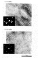
そして、本発明の工具鋼での、その組織の変調構造の形成は、電子線入射方向を<011>bccと平行にした回折図形において、基本格子反射周りの衛星斑点(超格子反射)の有無で評価できることを明らかにした。一例として、変調構造が形成された試料での回折図形を図1に示す。これより<011>基本格子反射周りに衛星斑点(超格子反射):矢印が確認され、これは原点と<011>bccスポット間距離の非整数分割の位置に現れている。
【0017】
また、変調構造が形成された領域は、上記の入射より得られる明視野像および暗視野像より判断した。一例として、変調構造が形成された領域の多波格子像(明視野像)を図2に示す。これより<011>方向の変調コントラストが現れており、変調の波長(周期)は{011}面間隔の5〜6倍であり、局所的にゆらいでいるのがわかる。
【0018】
変調構造は、300〜700℃の範囲での焼戻し処理によって形成され、マトリックス中のMoの濃度ゆらぎに起因している。また、焼戻し過程でMC、M7C3、M23C6、M6Cなど特殊合金炭化物が析出することによって、その炭化物にMoが取られるため変調構造は消滅し始める。つまり、変調構造の形成状態は焼戻し過程での特殊合金炭化物の析出挙動に大きく左右されるので、微量添加元素や熱処理条件によっても顕著に種々変化する。なかでも、本発明の工具鋼を高強度化して使用する場合、上述の範囲内での低めの温度で焼戻しを実施するため、ナノメータサイズの特殊合金炭化物が少量析出しているだけで、変調構造がほぼ全面に形成された状態となる傾向が強くなる。
【0019】
機械的性質については、室温および高温の強度は、変調コントラストが強いほど、かつ、変調構造がより全面に形成されるほど向上する。変調コントラストはMoの濃度ゆらぎと対応しており、そのゆらぎが大きいほど変調コントラストが強い。変調コントラストは、基本格子反射の回折強度と衛星斑点(超格子反射)の回折強度の比(衛星斑点(超格子反射)の回折強度/基本格子反射の回折強度)に対応し、この比が大きいと変調コントラストが強くなる。
【0020】
一方、靭性は、変調構造が形成され始めると低下するようになり、変調コントラストが強いほど、かつ、変調構造がより全面に形成されるほど著しく低下する。Moを多く含有した工具鋼では変調コントラストが強く、かつ、変調構造がより全面に形成される傾向にあり、室温および高温の強度が向上するものの靭性が著しく低下する。
【0021】
以上、工具鋼での機械的性質に及ぼす組織要因が明らかになり、その組織の変調構造を調整することで、工具鋼のような粒子分散強化で高強度化していると考えられていた材料の高強度化、高靭性化、そして強度−靭性バランスの向上も図れる。そして、この原理を解明したことによって提案に至った本発明の製造方法を用いることで、各種用途に適した素材であるかどうかの評価、特に各種工具に適用される工具鋼を対象にして、その適用のための最適組成や熱処理条件、さらにはその用途の最適性を評価できる。
【0022】
以下に、本発明の製造方法の効果を最大限に活用するのに好ましい、その製造対象である工具鋼の成分を限定した理由について詳細に説明する。
・MoおよびWの1種または2種を(Mo+0.5W)で0.1〜16.0質量%
Moは変調構造を形成して高温強度を向上させるのに必要であり、特に、工具鋼といったCを含む鋼材料では炭化物を形成して基地の強化や耐摩耗性を向上させ、また、焼入性を向上させる効果を有する。これら各々のより顕著な効果を期待する場合は、Moを0.1質量%以上とすることが望ましい。ただし、Moの過度の添加は変調構造を発達させ、また鋼材料においては炭化物量を増加させ、靭性の低下を招くため、Moの上限を16.0質量%とする。
【0023】
本発明の変調構造については、上記ではMoを例にとって説明したが、MoとWは同等の効果を有する元素であり、Wであっても同様に変調構造を形成して高温強度を向上させる元素である。本発明の製造方法は、特に工具鋼へ適用して効果を発揮するものであるところ、MoおよびWは工具鋼の機械的性質を左右する基幹元素である。よって、本発明が改善する工具鋼はMoおよび/またはWの含有も意識したものとすることで、その効果が向上する。
【0024】
WはMoの約2倍の原子量であることからMo+0.5Wで規定する(当然、いずれか一方のみの添加としてもよいし、双方を共添加することもできる)。そして、上記した各々の作用により顕著な効果を期待する場合は、Mo+0.5Wを0.1質量%以上とすることが望ましい。ただし、Moおよび/またはWの過度の添加は変調構造を発達させ、また炭化物量を増加させ、靭性の低下を招くため、Mo+0.5Wの上限を16.0質量%とする。
【0025】
・Cr:18.0質量%以下(0%を含む)
Crは焼入れ性を高めて、また、炭化物を形成して基地の強化や耐摩耗性を向上させる効果を有することから、用途に応じて鋼材料に含有させることができ、本発明の製造方法の効果を向上させる。ただし、より顕著な効果を期待する場合は、含有量を0.1質量%以上とすることが望ましい。過度の添加は焼入性や熱間強度の低下を招くため、上限を18.0質量%とする。
【0026】
・Cあるいは、Cおよび/またはNを合計で0.1〜3.0質量%
Cは、一部が基地中に固溶して強度を付与し、一部は炭化物を形成することで耐摩耗性や耐焼付き性を高める重要な元素であることから、本発明の製造方法の効果を向上させる。また、固溶したCは、CrやMoなどのCやNとの親和力の大きい置換型原子と共添加した場合、I(侵入型原子)−S(置換型原子)効果;溶質原子のひきずり抵抗として作用し高強度化する場合もある。ただし、含有量が0.1質量%未満では工具鋼として十分な硬さ、耐摩耗性を確保できなくなる。他方、過度の添加は靭性や熱間強度の低下を招くため上限を3.0質量%とする。
【0027】
Nは、鋼などの鉄基材料の製造上、不可避的に混入する元素である。他方、Ti、Al、Vなどと窒化物を形成し、結晶粒の微細化に有効であるため工具鋼の分野等においては積極的に添加する場合もある。また、固溶したNは、固溶したCと同様で、I(侵入型原子)−S(置換型原子)効果として作用し高強度化する場合もある。ただし、NとCは同等の効果を有する侵入型元素であり、工具鋼のようなCの調整が重要な鉄基材料を評価する時には、そのC量との相互管理をしておくことが評価結果の信頼性を向上させる。
【0028】
NとCはほぼ同等の原子量であることからCおよび/またはNを合計で規定する(当然、いずれか一方のみの添加としてもよいし、双方を共添加することもできる)。より顕著な効果を期待する場合は、Cおよび/またはNを合計で0.1質量%以上とすることが望ましい。ただし、Cおよび/またはNの過度の添加は炭化物/窒化物量を増加させ、靭性の低下を招くため、Cおよび/またはNの合計の上限を3.0質量%とする。なお、Nを単独で管理する場合、0.01%以上の含有で十分な効果を発揮できるが、1.2%以下の範囲で管理することが好ましい。
【0029】
なお、本発明の製造する工具鋼は、上記の各成分に加えて、その特に工具鋼材料としての成立に管理の欠かせない元素種として、
・Si:3.0質量%以下(好ましくは0.1〜3.0%)
・Mn:2.0質量%以下(好ましくは0.1〜2.0%)
・V:6.0質量%以下(好ましくは0.1〜6.0%)
を含有する。そして、
・Ni:3.0質量%以下(好ましくは0.1〜3.0%)
・Co:15.0質量%以下(好ましくは0.3〜15.0%)
・Al:0.1質量%以下
の群から選ばれた1種または2種以上を含有させることができる。
【0030】
また、本発明の製造する工具鋼には、必要に応じて
・S:0.20質量%以下
・Ca:0.050質量%以下
・Pb,Bi:各々0.2質量%以下(好ましくは0.02〜0.2質量%)
・B:0.010質量%以下(好ましくは0.001〜0.010質量%)
・Nb,Ti,Ta,Zr:
各々0.05質量%以下(好ましくは0.005〜0.05質量%)
・希土類金属元素(REM):各々0.50質量%以下
の1種または2種以上の元素を含有させることができる。
【0031】
【実施例】
つぎに実施例により、本発明の効果を説明する。
(実施例1)
供試材は、高周波誘導溶解により表1に示す組成に調整し作製した。供試材Aは熱間工具鋼JIS SKD61に相当する材料である。試料は、焼鈍を行ったのち、種々の熱処理を施し各種実験に供した。熱処理は所定の硬さを得るように、焼入れは1020℃で1時間加熱してから油冷し、その後焼戻しとして500℃から700℃の20℃刻みの適正温度で2時間加熱後空冷するものである。
【0032】
【表1】
組織観察については、α’マルテンサイト内部組織や炭化物の形態および凝集挙動、実用焼戻し温度域で析出したナノメータサイズ特殊炭化物および変調構造の直接観察には、200kV透過型電子顕微鏡(TEM)および200kV電界放射型透過型電子顕微鏡(FE−TEM)を用いて行った。変調構造の構造解析は電子線回折法を用いて実施した。電顕観察用試料は、超音波加工したのち、研磨、ディンプリングして、最後に電解研磨およびArイオンミリングを行い作製した。
【0034】
引張試験は、インストロン型試験機を使用し、室温(24±2℃)および高温ともで平行部径6.35mm、平行部長さ25.4mmの丸棒試験片(ASTM)を用いて歪み速度0.2s−1で行った。高温引張では、大気雰囲気で昇温速度25℃・s−1で600℃の試験温度まで加熱して0.6ks保持後、試験を実施した。機械的性質については、室温の場合は硬さ、伸び、絞りで、高温の場合は引張強さで評価した。なお、伸びは破断後の試料でのつき合わせ法で測定した。
【0035】
靭性の評価は、まず、Uノッチ試験片(JIS3号)を用いてシャルピー衝撃試験を実施し、室温(24±2℃)でのシャルピー衝撃値を測定した。つぎに、破壊靭性試験は、ASTM E399 コンパクトテンション試験片(W=30.0mm)を用いて、平面歪み破壊靭性値KICを測定した。表2に供試材Aの機械的性質と変調構造の形成状態の関係を、図3に表2で変調構造が形成されている代表的な試料の回折図形と多波格子像(明視野像)を示す。A3には特殊合金炭化物が確認される。
【0036】
【表2】
これより、A1とA2の硬さ40HRCの場合は変調構造が観察されず機械的性質に差がほとんどないことがわかる。つぎに、A3とA4の硬さ44HRCの場合は変調構造が形成され機械的性質にやや差を生じており、変調構造が多く形成されているA4で高温強度がやや高い値であるが靭性がやや低下しているのがわかる。また、A5とA6の硬さ50HRCの場合は変調構造がほぼ全面に形成されているためどちらの試料も靭性が非常に低い値であるが、特に変調コントラストが強く、かつ、変調構造がより全面に形成されているA6でそれが顕著であることがわかる。
【0038】
(実施例2)
供試材は、高周波誘導溶解により表3に示す組成に調整し作製した。供試材Cは熱間工具鋼JIS SKD7に相当する材料である。試料は、焼鈍を行ったのち、種々の熱処理を施し各種実験に供した。
【0039】
【表3】
熱処理は硬さ44HRCを得るように、焼入れは1020℃で1時間加熱してから油冷し、その後焼戻しとして600℃から700℃の適正温度で2時間加熱後空冷するものである。表4に供試材BとCの機械的性質と変調構造の形成状態の関係を、図4に変調構造が形成されている供試材BとCの回折図形と多波格子像(明視野像)を示す。
【0041】
【表4】
これより、Moを多く含有する供試材Cが供試材Bより変調コントラストが強く、かつ、変調構造がより全面に形成される傾向にあり、高温強度が高い値であるものの靭性が著しく低下しているのがわかる。
【0043】
(実施例3)
供試材は、高周波誘導溶解により表5に示す組成に調整し作製した。供試材Dは熱間工具鋼JIS SKD8に相当する材料である。試料は、焼鈍を行ったのち、種々の熱処理を施し各種実験に供した。
【0044】
【表5】
熱処理は硬さ44HRCを得るように、焼入れは1140℃で1時間加熱してから油冷し、その後焼戻しとして600℃から700℃の適正温度で2時間加熱後空冷するものである。表6に供試材DとEの機械的性質と変調構造の形成状態の関係を、図5に変調構造が形成されている供試材DとEの回折図形と多波格子像(明視野像)を示す。
【0046】
【表6】
これより、両者とも(Mo+0.5W)が約2.6質量%であるが、Wを多く含有する供試材Dが供試材Eより変調コントラストが強く、かつ、変調構造がより全面に形成される傾向にあり、高温強度が高い値であるものの靭性が低下しているのがわかる。
【0048】
(実施例4)
供試材は、高周波誘導溶解により表7に示す組成に調整し作製した。供試材Fは高速度工具鋼JIS SKH51、供試材Gはマトリックスハイスに相当する材料である。試料は、焼鈍を行ったのち、種々の熱処理を施し各種実験に供した。
【0049】
【表7】
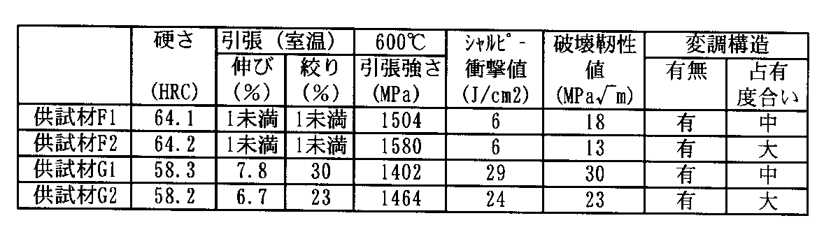
供試材Fの場合、熱処理は硬さ64HRCを得るように、焼入れは1220℃で0.5時間加熱してから油冷し、また供試材Gの場合、焼入れは1140℃で0.5時間加熱してから油冷した。その後、どの供試材も焼戻しとして600℃から700℃の適正温度で2時間加熱後空冷するものである。表8に供試材FとGの機械的性質と変調構造の形成状態の関係を、図6、図7に変調構造が形成されている供試材FとGの回折図形と多波格子像(明視野像)を示す。
【0051】
【表8】
これより、供試材Fは(Mo+0.5W)が約8.1質量%で、供試材F2が供試材F1より変調コントラストが強く、かつ、変調構造がより全面に形成される傾向にあり、高温強度が高い値であるものの靭性が低下しているのがわかる。また、供試材Gは(Mo+0.5W)が約2.8質量%で、供試材G2が供試材G1より変調コントラストが強く、かつ、変調構造がより全面に形成される傾向にあり、高温強度が高い値であるものの靭性が低下している。
【0053】
このような結果は、従来の工具鋼も含め、本発明が対象とするその他の成分組成を有する工具鋼であっても同様の挙動を示し、Wを含有する工具鋼においてはそのWの構成する濃度ゆらぎに応じても同傾向の機械的性質の変化を認めた。
【0054】
【発明の効果】
本発明によれば、工具鋼での機械的性質に及ぼす組織の影響が明確になり、かつ変調構造の形成を制御することが可能となるため強度−靭性バランスを飛躍的に改善することができ、安定した品質の素形材料の実用化にとって欠くことのできない技術となる。
【図面の簡単な説明】
【図1】変調構造が形成された試料での回折図形であり、本発明の一例を説明するものである。
【図2】変調構造が形成された領域の多波格子像(明視野像)であり、本発明の一例を説明する電子顕微鏡写真である。
【図3】本発明の実施例で評価した代表的な試料の回折図形と多波格子像(明視野像)であり、本発明の一例を説明する電子顕微鏡写真である。
【図4】本発明の実施例で評価した供試材の回折図形と多波格子像(明視野像)であり、本発明の一例を説明する電子顕微鏡写真である。
【図5】本発明の実施例で評価した供試材の回折図形と多波格子像(明視野像)であり、本発明の一例を説明する電子顕微鏡写真である。
【図6】本発明の実施例で評価した供試材の回折図形と多波格子像(明視野像)であり、本発明の一例を説明する電子顕微鏡写真である。
【図7】本発明の実施例で評価した供試材の回折図形と多波格子像(明視野像)であり、本発明の一例を説明する電子顕微鏡写真である。[0001]
BACKGROUND OF THE INVENTION
The present invention relates to a method for manufacturing a tool steel for improving mechanical properties such as strength and toughness by adjusting concentration fluctuations of Mo and W constituting a modulation structure of the structure of the tool steel.
[0002]
[Prior art]
Conventionally, high strength materials achieve high strength by combining various strengthening mechanisms. In particular, in the case of a general-purpose high-strength material, it is important to perform machining efficiently and to easily obtain high strength when used. Therefore, particle dispersion strengthening that can be easily processed with low hardness in the annealed state and can be increased in strength by subsequent quenching, aging treatment or tempering treatment is widely used. The dispersed particles are various and diverse, for example, different types of carbides for high speed steel, intermetallic compounds such as η-Ni 3 Ti or β-NiAl for precipitation hardened stainless steel, γ-BeCu, aluminum alloy for copper based alloys Then, it is an intermetallic compound such as θ-CuAl 2 .
[0003]
The increase in yield strength of these materials can be estimated by evaluating the size, volume ratio, consistency, etc. of the dispersed particles (see, for example, Non-Patent Document 1). On the other hand, the toughness is better when the volume fraction of the second phase particles (dispersed particles) is as small as possible. That is, a high-strength material using particle dispersion strengthening is provided as an industrial product by balancing the strength and toughness so as to satisfy the required characteristics by evaluating the above-described factors.
[0004]
Further, as a mechanism for increasing the strength different from the particle dispersion strengthening, a high-strength material using a modulation structure formed by spinodal decomposition has been proposed. For example, there are few research examples, but there are Cu—Ni—Sn alloys and the like which are considered as lead frame materials such as Fe—Mo binary alloys and IC elements. In the case of an Fe-Mo binary alloy that is an iron-based material, it has been reported that a modulation structure is formed by spinodal decomposition and exhibits a high hardness reaching Vickers hardness 1100 (for example, see Non-Patent
[0005]
[Non-Patent Document 1]
“Metal Handbook” Revised 6th Edition The Japan Institute of Metals Maruzen Co., Ltd. (2000), p. 318
[0006]
[Non-Patent Document 2]
“Metal” vol. 67 No. 5 (1997), p. 395
[0007]
[Non-Patent Document 3]
"Proc of inter Symposium on Phase Transformations During Thermal Mechanical Processing of Steel." Ed. By EB Hawbolt and S. Yue. (1995), p. 473
[0008]
[Problems to be solved by the invention]
However, until now, mechanical strength differences that cannot be explained even by performing the above-described factor analysis may occur in materials that have been strengthened by particle dispersion strengthening such as tool steel. There was a problem of low toughness in the material to be used. In particular, since the recent market trend is to reduce the weight and extend the service life, it has become necessary to increase the strength of the shaped material, and the above problems have become prominent. This problem is a major issue in efficiently providing industrial products that should guarantee stable quality. Moreover, since the cause of this problem has not been known, the heat treatment such as annealing, quenching, and tempering has been performed again, and much man-hours have been required.
[0009]
On the other hand, an Fe—Mo binary alloy needs to contain 20% by mass or more of expensive Mo in order to form a modulation structure, and although high hardness is obtained, it is very brittle and not suitable for practical use. It is possible to improve toughness to some extent by adding Co and V elements, but it is also necessary to add about 40% by mass of expensive Co, and there is a problem of cost when applied to tool steel etc. which is a raw material. This is very difficult.
[0010]
The purpose of the present invention is a material such as tool steel that has been considered to have increased strength by strengthening particle dispersion, and achieved higher strength, higher toughness, and balance between strength and toughness in accordance with market needs. In order to efficiently provide industrial products of stable quality, it is to provide a manufacturing method for improving the mechanical properties by clarifying the structural factors affecting the mechanical properties of the tool steel.
[0011]
[Means for Solving the Problems]
The present inventor conducted a detailed nanostructure analysis using existing materials, and intensively studied the influence of the structure on the mechanical properties. As a result, it has been found that a modulated structure is formed even in tool steel that does not contain much Mo, and it has also been clarified that this has a great influence on the strength-toughness balance. In addition, the modulation structure changed variously depending on the trace amount of added elements and heat treatment conditions, and it was also clarified that the strength-toughness balance changed significantly. Based on this, it was found that the balance between strength and toughness can be adjusted freely by controlling the formation of the modulation structure, and in particular, the validity of the specific application of the tool steel applied to various tools can be proposed. The present invention has been reached as a production method.
[0012]
That is, the present invention is, in mass%, C: 0.1 to 3.0% , Si: 3.0% or less, Mn: 2.0% or less, Cr: 0 to 18.0%, Mo and W 1 A method for producing a tool steel containing 0.1 or 16.0% of seeds or two kinds (Mo + 0.5W) , V: 6.0% or less , the balance being Fe and inevitable impurities ,
The balance between strength and toughness can be adjusted by adjusting the Mo and W contents and / or the conditions of tempering in the range of 300 to 700 ° C. after quenching to control the modulation structure of the tool steel structure. A method for producing tool steel characterized by the following. Or, in mass%, C and / or N is 0.1 to 3.0% in total, Si: 3.0% or less, Mn: 2.0% or less, Cr: 0 to 18.0%, Mo and A method for producing a tool steel comprising one or two W (Mo + 0.5W) in an amount of 0.1 to 16.0% and V: 6.0% or less , the balance being Fe and inevitable impurities ,
The balance between strength and toughness can be adjusted by adjusting the Mo and W contents and / or the conditions of tempering in the range of 300 to 700 ° C. after quenching to control the modulation structure of the tool steel structure. A method for producing tool steel characterized by the following.
[0013]
The method for producing a tool steel of the present invention is, for example, the tool steel, by mass%, N i: 3.0% or less, C o: 15.0% or less, Al: 0.1% or less groups If it contains one or two or more selected ones, it is particularly effective as a technique for improving the balance between strength and toughness as tool steel. Alternatively, the tool steel is, in mass%, S: 0.20% or less, Ca: 0.050% or less, Pb: 0.2% or less, Bi: 0.2% or less, B: 0.010%. Hereinafter, Nb: 0.05% or less, Ti: 0.05% or less, Ta: 0.05% or less, Zr: 0.05% or less, rare earth metal elements: one or two kinds each of 0.50% or less You may contain the above element. And it is an effective manufacturing method which can increase the strength or toughness and further improve the strength-toughness balance according to the market needs by controlling the formation of the structure modulation structure with the tool steel.
[0014]
DETAILED DESCRIPTION OF THE INVENTION
As mentioned above, an important feature of the present invention is that it employs the control of the formation of the modulated structure of the tool steel structure as a way to improve the mechanical properties , specifically the balance between strength and toughness. It is in. And it is in establishing as a manufacturing method which can propose even the validity of the specific use applied to the tool steel especially applied to various tools.
[0015]
First , the observation method for controlling the modulation structure of the structure of the tool steel forming the basis of the present invention will be described. The structure of the tool steel is observed using a transmission electron microscope. The specific evaluation in the present invention is that sample preparation is performed by electrolytic polishing or ion milling, acceleration voltage: 200 kV, magnification: up to 400,000, electron beam diffraction (restricted field diffraction method) and bright field / dark field image. Observed.
[0016]
In the tool steel of the present invention, the modulation structure of the structure is formed by the presence or absence of satellite spots (superlattice reflection) around the basic grating reflection in the diffraction pattern in which the electron beam incident direction is parallel to <011> bcc. It was clarified that it can be evaluated by. As an example, FIG. 1 shows a diffraction pattern of a sample in which a modulation structure is formed. From this, satellite spots (superlattice reflection) around the <011> basic lattice reflection: an arrow is confirmed, which appears at a non-integer division position of the distance between the origin and the <011> bcc spot.
[0017]
The region where the modulation structure was formed was judged from the bright field image and the dark field image obtained by the above incidence. As an example, FIG. 2 shows a multiwave lattice image (bright field image) of a region where a modulation structure is formed. From this, the modulation contrast in the <011> direction appears, and the modulation wavelength (period) is 5 to 6 times the {011} plane interval, and it can be seen that the modulation is locally fluctuating.
[0018]
The modulation structure is formed by a tempering process in the range of 300 to 700 ° C., and is caused by fluctuation in the concentration of Mo in the matrix. Further, when a special alloy carbide such as MC, M 7 C 3 , M 23 C 6 , or M 6 C is precipitated in the tempering process, Mo is taken in the carbide, and the modulation structure starts to disappear. That is, the formation state of the modulation structure is greatly affected by the precipitation behavior of the special alloy carbide during the tempering process, and thus varies significantly depending on the trace amount of added elements and heat treatment conditions. In particular, when the tool steel of the present invention is used with high strength, the tempering is performed at a lower temperature within the above-mentioned range. Tends to be in a state of being formed almost on the entire surface.
[0019]
Regarding the mechanical properties, the strength at room temperature and high temperature is improved as the modulation contrast is stronger and the modulation structure is formed on the entire surface. The modulation contrast corresponds to the Mo density fluctuation, and the modulation fluctuation is stronger as the fluctuation is larger. The modulation contrast corresponds to the ratio between the diffraction intensity of the basic grating reflection and the diffraction intensity of the satellite spot (superlattice reflection) (the diffraction intensity of the satellite spot (superlattice reflection) / the diffraction intensity of the basic grating reflection), and this ratio is large. And the modulation contrast becomes stronger.
[0020]
On the other hand, the toughness starts to decrease when the modulation structure starts to be formed, and decreases as the modulation contrast becomes stronger and the modulation structure is formed on the entire surface. The tool steel containing a large amount of Mo has a strong modulation contrast and a tendency that the modulation structure is formed on the entire surface, and the toughness is remarkably lowered although the strength at room temperature and high temperature is improved.
[0021]
As described above, the structural factors affecting the mechanical properties of tool steel have been clarified, and by adjusting the modulation structure of the structure, the strength of the material that was thought to be strengthened by particle dispersion strengthening such as tool steel Higher strength, higher toughness, and improved strength-toughness balance can be achieved. And by using the manufacturing method of the present invention that led to the proposal by elucidating this principle, evaluation of whether it is a material suitable for various uses, especially for tool steel applied to various tools, It is possible to evaluate the optimal composition and heat treatment conditions for the application, and the optimality of the application.
[0022]
The reason why the components of the tool steel that is the object of production, which is preferable for maximizing the effects of the production method of the present invention, will be described in detail below.
-0.1 or 16.0 mass% of 1 or 2 types of Mo and W in (Mo + 0.5W)
Mo is necessary to improve the high-temperature strength by forming a modulation structure. In particular, in steel materials containing C such as tool steel, carbide is formed to improve the strengthening and wear resistance of the base, and quenching is also performed. It has the effect of improving the property. When expecting more remarkable effects of each of these, it is desirable that Mo be 0.1% by mass or more. However, excessive addition of Mo develops a modulation structure and increases the amount of carbides in the steel material, leading to a decrease in toughness. Therefore, the upper limit of Mo is set to 16.0% by mass.
[0023]
Although the modulation structure of the present invention has been described above by taking Mo as an example, Mo and W are elements having the same effect, and even W is an element that similarly forms a modulation structure and improves high-temperature strength. It is. The production method of the present invention is particularly effective when applied to tool steel. Mo and W are key elements that influence the mechanical properties of tool steel. Accordingly, the effect of the tool steel improved by the present invention is improved by considering the inclusion of Mo and / or W.
[0024]
Since W has an atomic weight approximately twice that of Mo, it is defined as Mo + 0.5W (of course, either one may be added or both may be added together). When the expect more pronounced effect on the action of each of the above, it is desirable that the Mo + 0.5 W and 0.1% by mass or more. However, excessive addition of Mo and / or W develops a modulation structure, increases the amount of carbides, and causes a decrease in toughness. Therefore, the upper limit of Mo + 0.5W is set to 16.0% by mass.
[0025]
・ Cr: 18.0% by mass or less (including 0%)
Cr has the effect of enhancing hardenability and forming carbides to improve the strengthening and wear resistance of the base, so that it can be contained in a steel material depending on the application. Improve the effect. However, when a more remarkable effect is expected, the content is preferably 0.1% by mass or more. Excessive addition causes a decrease in hardenability and hot strength, so the upper limit is made 18.0% by mass.
[0026]
-C or C and / or N in total 0.1 to 3.0 mass%
C is an important element that increases the wear resistance and seizure resistance by partly dissolving in the matrix and imparting strength, and partly forming carbides. Improve the effect. In addition, when C is added together with substitutional atoms having a high affinity for C and N such as Cr and Mo, I (interstitial atom) -S (substitutional atom) effect; drag resistance of solute atoms In some cases, the strength increases. However, if the content is less than 0.1% by mass, sufficient hardness and wear resistance as tool steel cannot be secured. On the other hand, excessive addition causes a decrease in toughness and hot strength, so the upper limit is made 3.0% by mass.
[0027]
N is an element inevitably mixed in the manufacture of iron-based materials such as steel. On the other hand, it forms nitrides with Ti, Al, V, etc. and is effective in refining crystal grains, so it may be actively added in the field of tool steel. Further, the solid solution N is the same as the solid solution C, and may act as an I (interstitial atom) -S (substitution atom) effect to increase the strength. However, N and C are interstitial elements having the same effect, and when evaluating an iron-based material in which adjustment of C is important, such as tool steel, it is evaluated that mutual management with the C amount is performed. Improve the reliability of the results.
[0028]
Since N and C have substantially the same atomic weight, C and / or N are defined in total (of course, either one may be added or both may be added together). When a more remarkable effect is expected, it is desirable that C and / or N is 0.1% by mass or more in total. However, excessive addition of C and / or N increases the amount of carbide / nitride and causes a decrease in toughness, so the upper limit of the total of C and / or N is 3.0 mass%. In addition, when managing N independently, although sufficient effect can be exhibited by containing 0.01% or more, it is preferable to manage in the range of 1.2% or less.
[0029]
In addition, in addition to the above components, the tool steel produced by the present invention is an element type that is indispensable for management particularly as a tool steel material,
Si: 3.0% by mass or less (preferably 0.1 to 3.0%)
Mn: 2.0% by mass or less (preferably 0.1 to 2.0%)
V: 6.0% by mass or less (preferably 0.1 to 6.0%)
Containing. And
Ni: 3.0% by mass or less (preferably 0.1 to 3.0%)
Co: 15.0% by mass or less (preferably 0.3 to 15.0%)
-Al: 1 type (s) or 2 or more types selected from the group of 0.1 mass% or less can be contained.
[0030]
Moreover, in the tool steel manufactured by the present invention, if necessary, S: 0.20 mass% or less, Ca: 0.050 mass% or less, Pb, Bi: 0.2 mass% or less each (preferably 0 .02 to 0.2% by mass)
B: 0.010% by mass or less (preferably 0.001 to 0.010% by mass)
Nb, Ti, Ta, Zr:
Each 0.05% by mass or less (preferably 0.005 to 0.05% by mass)
-Rare earth metal element (REM): One or more elements of 0.50% by mass or less can be contained.
[0031]
【Example】
Next, the effects of the present invention will be described with reference to examples.
Example 1
The test material was prepared by adjusting the composition shown in Table 1 by high-frequency induction melting. The specimen A is a material corresponding to the hot work tool steel JIS SKD61. The sample was annealed and then subjected to various heat treatments for various experiments. In order to obtain a predetermined hardness, the heat treatment is performed by heating at 1020 ° C. for 1 hour, then oil cooling, and then tempering by heating at an appropriate temperature in increments of 20 ° C. from 500 ° C. to 700 ° C. and air cooling for 2 hours. is there.
[0032]
[Table 1]
For the structure observation, α ′ martensite internal structure, carbide morphology and agglomeration behavior, nanometer-size special carbide precipitated in a practical tempering temperature range, and a modulated structure are directly observed. The measurement was performed using a radiation transmission electron microscope (FE-TEM). The structural analysis of the modulation structure was performed using an electron diffraction method. The sample for electron microscope observation was prepared by performing ultrasonic processing, polishing and dipping, and finally performing electrolytic polishing and Ar ion milling.
[0034]
The tensile test was performed using an Instron type tester, using a round bar test piece (ASTM) having a parallel part diameter of 6.35 mm and a parallel part length of 25.4 mm at both room temperature (24 ± 2 ° C.) and high temperature. Performed at 0.2 s −1 . In the high-temperature tension, the test was performed after heating to a test temperature of 600 ° C. at a temperature rising rate of 25 ° C. · s −1 in an air atmosphere and maintaining 0.6 ks. The mechanical properties were evaluated by hardness, elongation and drawing at room temperature, and tensile strength at high temperature. Elongation was measured by a butt-on method with a sample after fracture.
[0035]
For the evaluation of toughness, first, a Charpy impact test was performed using a U-notch specimen (JIS No. 3), and a Charpy impact value at room temperature (24 ± 2 ° C.) was measured. Next, in the fracture toughness test, the plane strain fracture toughness value K IC was measured using an ASTM E399 compact tension test piece (W = 30.0 mm). Table 2 shows the relationship between the mechanical properties of the specimen A and the formation state of the modulation structure, and FIG. 3 shows the diffraction pattern and multi-wave grating image (bright-field image) of a representative sample in which the modulation structure is formed in Table 2. ). A3 is a special alloy carbide.
[0036]
[Table 2]
From this, it can be seen that when the hardness of A1 and A2 is 40 HRC, the modulation structure is not observed and there is almost no difference in mechanical properties. Next, in the case of the hardness 44HRC of A3 and A4, the modulation structure is formed and there is a slight difference in mechanical properties. The high temperature strength is slightly high in A4 where a large number of modulation structures are formed, but the toughness is high. You can see that it is slightly lower. Although the case hardness 50HRC of A5 and A6 is a very low value even toughness both samples for the modulation structure is formed on substantially the entire surface, particularly strong modulation contrast and modulation structure is more entire It can be seen that this is remarkable in A6 formed in FIG.
[0038]
(Example 2)
The test material was prepared by adjusting the composition shown in Table 3 by high-frequency induction melting. The specimen C is a material corresponding to the hot work tool steel JIS SKD7. The sample was annealed and then subjected to various heat treatments for various experiments.
[0039]
[Table 3]
In order to obtain a hardness of 44 HRC in the heat treatment, the quenching is performed by heating at 1020 ° C. for 1 hour and then oil cooling, followed by heating at an appropriate temperature of 600 ° C. to 700 ° C. for 2 hours and then air cooling. Table 4 shows the relationship between the mechanical properties of the test materials B and C and the formation state of the modulation structure, and FIG. 4 shows the diffraction patterns and multiwave grating images (bright field) of the test materials B and C on which the modulation structure is formed. Image).
[0041]
[Table 4]
As a result, the specimen C containing a large amount of Mo has a stronger modulation contrast than the specimen B, and the modulation structure tends to be formed on the entire surface, and the toughness is significantly reduced although the high-temperature strength is high. You can see that
[0043]
(Example 3)
The test material was prepared by adjusting the composition shown in Table 5 by high-frequency induction melting. The specimen D is a material corresponding to the hot work tool steel JIS SKD8. The sample was annealed and then subjected to various heat treatments for various experiments.
[0044]
[Table 5]
In order to obtain a hardness of 44 HRC, the heat treatment is performed by heating at 1140 ° C. for 1 hour and then oil cooling, followed by tempering at 600 to 700 ° C. for 2 hours and air cooling. Table 6 shows the relationship between the mechanical properties of the test materials D and E and the formation state of the modulation structure, and FIG. 5 shows the diffraction patterns and multiwave grating images (bright field) of the test materials D and E on which the modulation structure is formed. Image).
[0046]
[Table 6]
From this, both (Mo + 0.5W) is about 2.6% by mass, but the specimen D containing a large amount of W has a stronger modulation contrast than the specimen E, and the modulation structure is formed on the entire surface. It can be seen that although the high-temperature strength is high, the toughness is reduced.
[0048]
(Example 4)
The test material was prepared by adjusting the composition shown in Table 7 by high frequency induction melting. The sample material F is a high-speed tool steel JIS SKH51, and the sample material G is a material corresponding to matrix high speed. The sample was annealed and then subjected to various heat treatments for various experiments.
[0049]
[Table 7]
In the case of the test material F, the heat treatment is performed by heating at 1220 ° C. for 0.5 hours and then oil cooling so that a hardness of 64 HRC is obtained. In the case of the test material G, the quenching is performed at 1140 ° C. at 0.5. It was heated for hours and then oil cooled. Thereafter, all the test materials are tempered and heated at an appropriate temperature of 600 ° C. to 700 ° C. for 2 hours and then air cooled. Table 8 shows the relationship between the mechanical properties of the test materials F and G and the formation state of the modulation structure, and FIGS. 6 and 7 show diffraction patterns and multiwave grating images of the test materials F and G on which the modulation structure is formed. (Bright field image) is shown.
[0051]
[Table 8]
Accordingly, the sample material F has a (Mo + 0.5W) of about 8.1% by mass, the sample material F2 has a stronger modulation contrast than the sample material F1, and the modulation structure tends to be formed on the entire surface. It can be seen that although the high-temperature strength is high, the toughness is reduced. Further, the sample material G has (Mo + 0.5W) of about 2.8% by mass, the sample material G2 has a stronger modulation contrast than the sample material G1, and the modulation structure tends to be formed on the entire surface. Although the high-temperature strength is high, the toughness is reduced.
[0053]
Such a result shows the same behavior even in the case of tool steels having other component compositions targeted by the present invention, including conventional tool steels. The same change in mechanical properties was observed depending on the concentration fluctuation.
[0054]
【The invention's effect】
According to the present invention, the influence of the structure on the mechanical properties of the tool steel becomes clear, and the formation of the modulation structure can be controlled, so that the strength-toughness balance can be dramatically improved. This technology is indispensable for the practical use of stable quality shaped materials.
[Brief description of the drawings]
FIG. 1 is a diffraction pattern of a sample on which a modulation structure is formed, and illustrates an example of the present invention.
FIG. 2 is a multiwave lattice image (bright field image) of a region where a modulation structure is formed, and is an electron micrograph illustrating an example of the present invention.
FIG. 3 is an electron micrograph illustrating an example of the present invention, showing a diffraction pattern and a multi-wave grating image (bright field image) of a representative sample evaluated in an example of the present invention.
FIG. 4 is an electron micrograph illustrating an example of the present invention, which is a diffraction pattern and a multiwave lattice image (bright field image) of a test material evaluated in an example of the present invention.
FIG. 5 is an electron micrograph illustrating an example of the present invention, which is a diffraction pattern and a multiwave lattice image (bright field image) of a test material evaluated in an example of the present invention.
FIG. 6 is an electron micrograph illustrating an example of the present invention, which is a diffraction pattern and a multiwave lattice image (bright field image) of a test material evaluated in an example of the present invention.
FIG. 7 is an electron micrograph illustrating an example of the present invention, which is a diffraction pattern and a multiwave lattice image (bright field image) of a test material evaluated in an example of the present invention.
Claims (7)
MoおよびWの含有量および/または焼入れ後の300〜700℃の範囲での焼戻しの条件を調整して、工具鋼の組織の変調構造を制御することにより、強度と靱性のバランスを調整することを特徴とする工具鋼の製造方法。In mass%, C: 0.1 to 3.0 %, Si: 3.0% or less, Mn: 2.0% or less, Cr: 0 to 18.0%, one or two of Mo and W (Mo + 0.5W) 0.1 to 16.0% , V: 6.0% or less , a method for producing a tool steel comprising the balance Fe and inevitable impurities ,
The balance between strength and toughness can be adjusted by adjusting the Mo and W contents and / or the conditions of tempering in the range of 300 to 700 ° C. after quenching to control the modulation structure of the tool steel structure. A method for producing tool steel characterized by the following.
MoおよびWの含有量および/または焼入れ後の300〜700℃の範囲での焼戻しの条件を調整して、工具鋼の組織の変調構造を制御することにより、強度と靱性のバランスを調整することを特徴とする工具鋼の製造方法。In mass%, C and / or N is 0.1 to 3.0% in total, Si: 3.0% or less, Mn: 2.0% or less, Cr: 0 to 18.0%, Mo and W 1 or 2 (Mo + 0.5W) 0.1 to 16.0% , V: 6.0% or less , a method for producing a tool steel comprising the balance Fe and inevitable impurities ,
The balance between strength and toughness can be adjusted by adjusting the Mo and W contents and / or the conditions of tempering in the range of 300 to 700 ° C. after quenching to control the modulation structure of the tool steel structure. A method for producing tool steel characterized by the following.
Priority Applications (1)
| Application Number | Priority Date | Filing Date | Title |
|---|---|---|---|
| JP2003133883A JP4257640B2 (en) | 2003-05-13 | 2003-05-13 | Tool steel manufacturing method |
Applications Claiming Priority (1)
| Application Number | Priority Date | Filing Date | Title |
|---|---|---|---|
| JP2003133883A JP4257640B2 (en) | 2003-05-13 | 2003-05-13 | Tool steel manufacturing method |
Publications (2)
| Publication Number | Publication Date |
|---|---|
| JP2004339532A JP2004339532A (en) | 2004-12-02 |
| JP4257640B2 true JP4257640B2 (en) | 2009-04-22 |
Family
ID=33524578
Family Applications (1)
| Application Number | Title | Priority Date | Filing Date |
|---|---|---|---|
| JP2003133883A Expired - Fee Related JP4257640B2 (en) | 2003-05-13 | 2003-05-13 | Tool steel manufacturing method |
Country Status (1)
| Country | Link |
|---|---|
| JP (1) | JP4257640B2 (en) |
Cited By (1)
| Publication number | Priority date | Publication date | Assignee | Title |
|---|---|---|---|---|
| KR102072606B1 (en) | 2018-10-02 | 2020-02-03 | 한국생산기술연구원 | Super high strength tool steel strip with high impact toughness and preparing method thereof |
Families Citing this family (6)
| Publication number | Priority date | Publication date | Assignee | Title |
|---|---|---|---|---|
| US20060213586A1 (en) * | 2005-03-23 | 2006-09-28 | Hin-Wing Kui | Metal composites and methods for forming same |
| CN100368569C (en) * | 2005-04-22 | 2008-02-13 | 广东巨轮模具股份有限公司 | Process and equipment for strengthening and toughening tyre mould |
| JP2007162114A (en) * | 2005-12-16 | 2007-06-28 | Sumitomo Metal Ind Ltd | Martensitic iron-base heat-resistant alloy |
| JP4779632B2 (en) * | 2005-12-16 | 2011-09-28 | 住友金属工業株式会社 | Martensitic iron-base heat-resistant alloy |
| JP5225596B2 (en) * | 2007-03-15 | 2013-07-03 | 株式会社不二Wpc | Method for strengthening alloy steel for hot mold and alloy steel for hot mold formed by suppressing generation of thermal fatigue crack by the method |
| JP5744300B1 (en) * | 2014-11-11 | 2015-07-08 | 日本高周波鋼業株式会社 | Hot work tool steel |
-
2003
- 2003-05-13 JP JP2003133883A patent/JP4257640B2/en not_active Expired - Fee Related
Cited By (2)
| Publication number | Priority date | Publication date | Assignee | Title |
|---|---|---|---|---|
| KR102072606B1 (en) | 2018-10-02 | 2020-02-03 | 한국생산기술연구원 | Super high strength tool steel strip with high impact toughness and preparing method thereof |
| US11008634B2 (en) | 2018-10-02 | 2021-05-18 | Korea Institute Of Industrial Technology | Tool steel having strength and high impact toughness |
Also Published As
| Publication number | Publication date |
|---|---|
| JP2004339532A (en) | 2004-12-02 |
Similar Documents
| Publication | Publication Date | Title |
|---|---|---|
| Hsu et al. | Effect of aluminum content on microstructure and mechanical properties of Al x CoCrFeMo0. 5Ni high-entropy alloys | |
| JP5710478B2 (en) | Hardened martensitic steel with a low content of cobalt, method for producing parts from the steel, and parts obtained thereby | |
| US20080031769A1 (en) | High-temperature resistant alloy with low contents of cobalt and nickel | |
| JP2019534374A (en) | Boron-doped high entropy alloy and method for producing the same | |
| JP5929963B2 (en) | Hardening method of steel | |
| CN108884529B (en) | Cr-based two-phase alloy and its products | |
| KR20140004718A (en) | High thermal diffusivity and high wear resistance tool steel | |
| WO2008032816A1 (en) | Hot-working tool steel having excellent stiffness and high-temperature strength and method for production thereof | |
| Soni et al. | Effect of alloying elements, phases and heat treatments on properties of high-entropy alloys: a review | |
| CA2873761C (en) | Method for producing objects from iron-cobalt-molybdenum/tungsten-nitrogen alloys | |
| EP1245689B1 (en) | Low-alloy heat-resistant steel, heat treatment method therefor, and turbine rotor comprising the same | |
| JP4964063B2 (en) | Case-hardened steel with excellent cold forgeability and grain coarsening prevention properties and machine parts obtained therefrom | |
| WO2015182586A1 (en) | Hot work tool material and method for manufacturing hot work tool | |
| EP4112754A1 (en) | Precipitation-hardening martensitic stainless steel | |
| JP4257640B2 (en) | Tool steel manufacturing method | |
| JP6569845B1 (en) | High carbon hot rolled steel sheet and manufacturing method thereof | |
| JP3987297B2 (en) | Powdered high-speed steel and high-speed steel tool with excellent coating properties | |
| JP3485805B2 (en) | Hot forged non-heat treated steel having high fatigue limit ratio and method for producing the same | |
| JP2007302950A (en) | High-strength spring steel wire superior in setting resistance | |
| JP5212774B2 (en) | Hot tool steel excellent in toughness and high temperature strength and method for producing the same | |
| JPH1017985A (en) | High strength steel excellent in hydrogen embrittlement resistance and its production | |
| JP5212772B2 (en) | Hot work tool steel with excellent toughness and high temperature strength | |
| WO2016186033A1 (en) | Spring steel | |
| JP2004219323A (en) | Method of evaluating iron base material | |
| JP2003313635A (en) | High toughness hot tool steel |
Legal Events
| Date | Code | Title | Description |
|---|---|---|---|
| A621 | Written request for application examination |
Free format text: JAPANESE INTERMEDIATE CODE: A621 Effective date: 20050916 |
|
| A977 | Report on retrieval |
Free format text: JAPANESE INTERMEDIATE CODE: A971007 Effective date: 20071026 |
|
| A131 | Notification of reasons for refusal |
Free format text: JAPANESE INTERMEDIATE CODE: A131 Effective date: 20071116 |
|
| A521 | Written amendment |
Free format text: JAPANESE INTERMEDIATE CODE: A523 Effective date: 20071228 |
|
| A131 | Notification of reasons for refusal |
Free format text: JAPANESE INTERMEDIATE CODE: A131 Effective date: 20081205 |
|
| A521 | Written amendment |
Free format text: JAPANESE INTERMEDIATE CODE: A523 Effective date: 20081212 |
|
| TRDD | Decision of grant or rejection written | ||
| A01 | Written decision to grant a patent or to grant a registration (utility model) |
Free format text: JAPANESE INTERMEDIATE CODE: A01 Effective date: 20090109 |
|
| A01 | Written decision to grant a patent or to grant a registration (utility model) |
Free format text: JAPANESE INTERMEDIATE CODE: A01 |
|
| A61 | First payment of annual fees (during grant procedure) |
Free format text: JAPANESE INTERMEDIATE CODE: A61 Effective date: 20090122 |
|
| R150 | Certificate of patent or registration of utility model |
Ref document number: 4257640 Country of ref document: JP Free format text: JAPANESE INTERMEDIATE CODE: R150 Free format text: JAPANESE INTERMEDIATE CODE: R150 |
|
| FPAY | Renewal fee payment (event date is renewal date of database) |
Free format text: PAYMENT UNTIL: 20120213 Year of fee payment: 3 |
|
| FPAY | Renewal fee payment (event date is renewal date of database) |
Free format text: PAYMENT UNTIL: 20130213 Year of fee payment: 4 |
|
| FPAY | Renewal fee payment (event date is renewal date of database) |
Free format text: PAYMENT UNTIL: 20140213 Year of fee payment: 5 |
|
| LAPS | Cancellation because of no payment of annual fees |