JP4268024B2 - Tire molding mold manufacturing method and tire molding mold - Google Patents
Tire molding mold manufacturing method and tire molding mold Download PDFInfo
- Publication number
- JP4268024B2 JP4268024B2 JP2003400374A JP2003400374A JP4268024B2 JP 4268024 B2 JP4268024 B2 JP 4268024B2 JP 2003400374 A JP2003400374 A JP 2003400374A JP 2003400374 A JP2003400374 A JP 2003400374A JP 4268024 B2 JP4268024 B2 JP 4268024B2
- Authority
- JP
- Japan
- Prior art keywords
- ring
- casting
- diameter
- inner diameter
- mold
- Prior art date
- Legal status (The legal status is an assumption and is not a legal conclusion. Google has not performed a legal analysis and makes no representation as to the accuracy of the status listed.)
- Expired - Fee Related
Links
Images










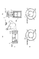
Landscapes
- Molds, Cores, And Manufacturing Methods Thereof (AREA)
- Moulds For Moulding Plastics Or The Like (AREA)
Description
本発明は、鋳造により製作されたタイヤ成形用金型の寸法精度を向上させるものであって、さらに詳しくは、リング状態で鋳造されたタイヤ成形金型用リング鋳物の意匠面部の直径,真円度特性を、簡易に精度高く狙い特性に矯正できるタイヤ成形用金型の製造方法、および該製造方法により製造されるタイヤ成形用金型に関する。 The present invention is to improve the dimensional accuracy of a tire molding die manufactured by casting, and more specifically, the diameter of a design surface portion of a ring casting for a tire molding die cast in a ring state, a perfect circle The present invention relates to a method for manufacturing a tire molding die that can easily correct the degree characteristic to a target characteristic with high accuracy, and a tire molding die manufactured by the manufacturing method.
タイヤ成形用金型は、複数に分割されたピース金型を組み付けることにより形成されており、タイヤ形状を幅方向に2分割することにより構成される上下分割型(2ピースモールド)と、半径方向(円周方向)に7〜13程度に分割することにより構成される上下一体型(セクショナルモールド)との2種類のタイヤ成形用金型が使用されている。 The tire molding die is formed by assembling a plurality of divided piece dies, and an upper and lower divided die (two piece mold) configured by dividing the tire shape into two in the width direction, and a radial direction. Two types of tire molding dies are used, which are an upper and lower integrated type (sectional mold) configured by dividing the outer circumference into about 7 to 13 in the (circumferential direction).
このようなタイヤ成形用金型においては、鋭い角を有した凹ブロック形状部分やサイプブレードなどの薄肉凸形状部分を多数有していることから、機械加工による製造が不向きであり、このため、鋳造によって製造されている。 In such a tire molding die, since it has a large number of thin convex portions such as concave block shape portions and sipe blades having sharp corners, it is not suitable for manufacturing by machining. Manufactured by casting.
鋳造製法の中でも、石膏鋳造法が使用されることが多い。これは、鋳型が崩壊性を持ち、アンダーカット形状対応の自由度が高く、鋳型での組み立て加工が簡易に行え、金型分割形状分をほぼ一体形状で鋳造でき、かつ、寸法精度が高い上、鋳型コストが低いことがその理由として挙げられる。 Of the casting methods, the gypsum casting method is often used. This is because the mold is collapsible, has a high degree of freedom in supporting undercut shapes, can be easily assembled with the mold, can be cast into a nearly integral shape, and has high dimensional accuracy. The reason is that the mold cost is low.
図14は、石膏鋳造法によって2ピースモールドを作製する手順を示す。まず、(a)に示すように石膏、樹脂などを用いてタイヤの原型(マスターモデル)1を機械加工で作製し、(b)で示すようにシリコーンゴムなどによって原型1を反転したゴム型2を作製する。そして、(c)で示すようにゴム型2から鋳型3を石膏によって反転作製し、この鋳型3を焼成乾燥した後、(d)で示すように複数角度で切断し、(e)で示すように組み立ててリング状の鋳型4とする。そして、(f)で示すように、この鋳型4を鋳枠5で囲み、鋳枠5内にアルミニウム合金等の合金溶湯6を充填して鋳造することにより鋳物とし、この鋳物に対して不要部分の除去のための機械加工を行い、その後、(g)で示すように型合わせを行ってタイヤ成形用金型8とする。(g)において、符号7は、タイヤ成形用金型を構成する複数の分割金型である。この分割金型7は、後述する図16に示すように、バックモールド9を用いることにより上下分割型に組み立てられ、この組み立てによってタイヤ成形用金型8が形成されるものである。
FIG. 14 shows a procedure for producing a two-piece mold by a gypsum casting method. First, a tire mold (master model) 1 is produced by machining using gypsum, resin, etc. as shown in (a), and a
図15は、石膏鋳造法によってセクショナルモールドを作製する手順を示し、図14と同様に、(a)で示すタイヤの原型1を反転した(b)のゴム型2を作製した後、(c)及び(d)で示すように石膏によって鋳型3を作製し、(e)で示すように組み立てて鋳型4とする。その後は、図14と同様に、アルミニウム合金等の鋳造金属による鋳造を行い、鋳物を型合わせして(f)で示すタイヤ成形用金型8とする。(f)において、符号7は図14と同様に、タイヤ成形用金型8を構成する分割金型である。
FIG. 15 shows a procedure for producing a sectional mold by a gypsum casting method. Similarly to FIG. 14, after producing a
さらに詳しくは、石膏鋳造法によるセクショナルモールドの作製方法は、第1セクショナルモールド法と第2セクショナルモールド法とに分けることができる。第1セクショナルモールド法は、セクター端面余肉設定法で、分割金型7が背面加工代および側面加工代等の後加工で除去される仕上げ加工代を有して形成されるものであり、第2セクショナルモールド法は、セクター端面余肉無し法で、分割金型7がセクターブロック両側面(端面)について仕上げ加工代無しで製作されるものである。
More specifically, the method for producing a sectional mold by the gypsum casting method can be divided into a first sectional mold method and a second sectional mold method. The first sectional mold method is a sector end face surplus setting method, in which the
以上の方法によって作製された複数の分割金型7は、図16に示すように、周方向で相互に隣接するように組み付けられるものであり、(a)はセクショナルモールドの場合、(b)は2ピースモールドの場合を示す。いずれにおいても、外側のバックモールド9に複数の分割金型7を取り付けてリング状に組み付けることによりタイヤ成形用金型8とする。
As shown in FIG. 16, the plurality of divided
このように、2ピースモールド法、第1セクショナルモールド法、および第2セクショナルモールド法は、いずれもリング状態で鋳造することから、アルミ合金溶湯の凝固・冷却収縮時に、リングの中心軸に対して不均一な歪みを発生させてしまうことが多く、これに起因して鋳放し鋳物(リング鋳物)の内面(意匠面)の真円度(基準真円からの振れ値幅)特性が悪化する傾向にある。 As described above, since the two-piece molding method, the first sectional molding method, and the second sectional molding method are all cast in a ring state, when the molten aluminum alloy is solidified and cooled, the center axis of the ring is reduced. In many cases, non-uniform distortion is generated, and due to this, the roundness of the inner surface (design surface) of an as-cast casting (ring casting) (running value width from the reference perfect circle) tends to deteriorate. is there.
また、鋳物の収縮バラツキも発生しやすく、これに起因して、リング鋳物内径も、狙いとするものから(許容公差を逸脱して)外れてしまう場合も有る。 Further, shrinkage variation of the casting is likely to occur, and due to this, the inner diameter of the ring casting may be deviated from the target (out of the allowable tolerance).
タイヤ成形金型において各部の直径と真円度は、タイヤ性能を決定づける重要な管理項目であり、その要求特性は、年々高い精度のものとなってきており、鋳造法による製作限界に近づきつつある。 The diameter and roundness of each part in tire molding dies are important management items that determine tire performance, and their required characteristics are becoming more and more accurate year by year, and are approaching the production limit of casting methods. .
たとえば、現状の要求精度は、許容公差数値が、直径で±0.2mm程度,真円度で0.25mm程度であり、さらに高精度仕様の場合は、直径で±0.1〜0.15mm,真円度で0.1〜0.15mmで、殆ど機械加工スペックに近いものとなっている。 For example, the current required accuracy is that the tolerance value is about ± 0.2 mm in diameter and about 0.25 mm in roundness, and in the case of high-precision specifications, it is ± 0.1 to 0.15 mm in diameter. The roundness is 0.1 to 0.15 mm, which is almost close to machining specifications.
このような観点から前述した従来の3つの石膏鋳造法によるタイヤ成形金型製法を総括してみるに、セクターブロック単位で真円の鋳物を製作することを狙う、第1セクショナルモールド法(端面余肉設定法)は、現行法の中では最も効果的に、これらの問題を解決している製法であると言える。 From this point of view, to summarize the three conventional gypsum casting methods for tire molding described above, the first section molding method (end face surplus) is aimed at producing a perfect circle casting in sector block units. The meat setting method) is the most effective method of solving these problems in the current method.
その理由は、半径(直径)特性については、リング状態で鋳造した鋳物を、円周方向にセクター分割した後に、所定の直径位置に内面(意匠面)が来る様に調整した後、セクター上下面加工、端面加工、及び、外周加工を行うことができるので、リング状態の時より半径(直径)特性を向上させることができる。 The reason for the radius (diameter) characteristics is that the casting cast in the ring state is divided into sectors in the circumferential direction, and then adjusted so that the inner surface (design surface) comes to the specified diameter position, then the upper and lower surfaces of the sector Since the machining, the end face machining, and the outer circumference machining can be performed, the radius (diameter) characteristic can be improved as compared with the ring state.
同じような理由で、真円度特性についても、第1セクショナルモールド法(端面余肉設定法)は、連続したリング状態では真円度特性が悪くても、セクター分割して、再度組み立て直す工程を経ることができるから(セクター分割面の両端部をゼロ位置に持ってきて、端面角度加工が可能となることから)、リング状態の時より真円度特性を向上させることができる。 For the same reason, with regard to the roundness characteristics, the first sectional mold method (end face surplus setting method) is a process of dividing and reassembling the sectors even if the roundness characteristics are poor in a continuous ring state. The roundness characteristics can be improved more than in the ring state because the both end portions of the sector dividing surface are brought to the zero position and the end surface angle machining is possible.
図17は、これら特性の向上を説明するもので、図17(a)はリング鋳物の状態で、鋳物の各部半径(直径)が狙い寸法(正規半径R)から外れ真円度特性が良くない場合を示しており、2ピースモールドでは、外力で矯正しない限り、このままの状態で金型として使用することになる。これに対して、第1セクショナルモールド法(端面余肉設定法)では、図17(b)に示すように、セクター分割後、円周方向Pf面両端部を正規の半径Rの位置とし、上下型間でも同じ半径となるようにセクターの位置調整をして外周加工を行うことができる(全セクター同様)。したがって、第1セクショナルモールド法(端面余肉設定法)では、セクター両端部を、正規半径Rの位置にシフトできる(図17(c)に示すように、セクター位置調整加工前→セクター位置調整加工後)ため、半径(直径)、真円度ともにリング状態時より改善される。 FIG. 17 illustrates the improvement of these characteristics. FIG. 17A shows the state of a ring casting, in which the radius (diameter) of each part of the casting deviates from the target dimension (normal radius R) and the roundness characteristics are not good. In this case, the two-piece mold is used as it is as a mold unless it is corrected by an external force. On the other hand, in the first sectional mold method (end face surplus setting method), as shown in FIG. 17 (b), after dividing the sector, both ends of the circumferential direction Pf surface are positioned at the normal radius R, and Peripheral machining can be performed by adjusting the position of the sector so that the radius is the same between molds (same as for all sectors). Therefore, in the first sectional mold method (end face surplus setting method), both end portions of the sector can be shifted to the position of the normal radius R (as shown in FIG. 17C, before sector position adjustment processing → sector position adjustment processing). Therefore, both the radius (diameter) and roundness are improved compared to the ring state.
このため第1セクショナルモールド法(端面余肉設定法)は、他の2つの製法には無いメリットが有る。 For this reason, the first sectional mold method (end surface surplus setting method) has an advantage not found in the other two manufacturing methods.
しかしながら、第1セクショナルモールド法(端面余肉設定法)は、前述した調整により、セクター分割面(両端面)部に、意匠面形状にズレ・歪みを発生させることが多くなると言うデメリットも存在する。 However, the first sectional mold method (end surface surplus setting method) also has a demerit that the design division shape often causes displacement / distortion in the sector division surface (both end surfaces) by the adjustment described above. .
加えて、第1セクショナルモールド法(端面余肉設定法)は、鋳物の外周加工工数が他の2つの製法と比べて多くなるので、金型コストが高くなる、という課題をも有している。 In addition, the first sectional molding method (end face surplus setting method) has a problem that the die cost increases because the man-hours for outer periphery processing of the casting are larger than those of the other two manufacturing methods. .
他方、2ピースモールド法および第2セクショナルモールド法は、真円を狙ってリング鋳物を製作するものであるが、製作されたリング鋳物の鋳放し直径、および真円度特性が、所定の数値に入らない場合には、機械加工による位置調整で補正ができないため、リング状態鋳物のままで、直径矯正や、真円度補正を行う必要が出てくる。 On the other hand, the two-piece molding method and the second sectional molding method are intended to manufacture a ring casting aiming at a perfect circle, but the as-cast diameter and roundness characteristics of the manufactured ring casting are set to predetermined values. If it does not enter, it cannot be corrected by position adjustment by machining. Therefore, it is necessary to correct the diameter or correct the roundness of the ring-shaped casting.
従来、直径矯正,真円度補正としては、直径(半径)拡張タイプ,または直径(半径)縮小タイプの2種類の方法が採用されている。 Conventionally, two methods of diameter (radius) expansion type and diameter (radius) reduction type have been adopted as diameter correction and roundness correction.
図18は、直径(半径)拡張タイプに用いるリング鋳物で、図18(a)は鋳放し状態のものA1で、図18(b)は鋳放し状態のものA1から押湯部分Bを取り除いたリング鋳物Aを示す。 FIG. 18 is a ring casting used for the diameter (radius) expansion type, FIG. 18A is an as-cast state A1, and FIG. 18B is an as-cast state A1 with the feeder part B removed. Ring casting A is shown.
図19は、直径(半径)拡張タイプの第1矯正方法を説明するもので、この第1矯正方法は、円盤を12〜20に分割した扇形スライド駒eを用いたカム式エキスパンダーEを拡張手段とするものであり、図18(b)のリング鋳物Aの鋳放し面aを基準径部として行うものである。 FIG. 19 illustrates a first correction method of the diameter (radius) expansion type. This first correction method uses a cam-type expander E that uses a fan-shaped slide piece e in which a disk is divided into 12 to 20 as an expansion means. In this case, the as-cast surface a of the ring casting A in FIG. 18B is used as a reference diameter portion.
図19(a)は、上下の鋳放し面aを利用して上下同時に扇形スライド駒eを同一量だけ張り出す方法であり、φd1,φd2を同時に拡張するものであり、図19(b)は、下側の鋳放し面aを利用して下側だけ扇形スライド駒eを一定量だけ張り出す方法であり、φd1側のみ拡張するものであり、図19(c)は、上側の鋳放し面aを利用して上側だけ扇形スライド駒eを一定量だけ張り出す方法であり、φd2側のみ拡張するものである。 FIG. 19 (a) is a method in which the upper and lower as-cast surfaces a are used to project the same amount of fan-shaped slide piece e at the same time up and down, and φd1 and φd2 are expanded at the same time, and FIG. FIG. 19 (c) shows an upper as-cast surface in which the lower as-cast surface a is used to project the fan-shaped slide piece e by a certain amount only on the lower side, and only the φd1 side is expanded. This is a method of extending a fan-shaped slide piece e by a certain amount only on the upper side using a, and expanding only the φd2 side.
また、図19中のA、B、Cは、それぞれの方法(a)、(b)、(c)における矯正状況、クラウンR形状変化、各部位の真円度をそれぞれ示している。 Further, A, B, and C in FIG. 19 indicate the correction status, crown R shape change, and roundness of each part in each of the methods (a), (b), and (c).
図19のBから明らかなように、(a)の場合、上下で張り出された部位近傍のみが直径(半径)が拡張されるだけで、中央部は、元の直径に近い状態 となり、所謂サバ折れ状態を呈するものであり、(b)の場合、下側の張り出された部位近傍の直径(半径)が拡張されると同時に、上側はその反作用で若干直径が縮小するものであり、(c)の場合、上側の張り出された部位近傍の直径(半径)が拡張されると同時に、下側はその反作用で若干直径が縮小するものである。 As can be seen from FIG. 19B, in the case of (a), only the diameter (radius) is expanded only in the vicinity of the part that protrudes vertically, and the central part is in a state close to the original diameter. In the case of (b), the diameter (radius) in the vicinity of the lower protruding portion is expanded, and at the same time, the diameter is slightly reduced by the reaction on the upper side, In the case of (c), the diameter (radius) in the vicinity of the upper protruding portion is expanded, and at the same time, the diameter is slightly reduced on the lower side due to the reaction.
また図19のCは、それぞれ内側の破線は鋳放し状態を、外側の実線は同部分の矯正後の状態を示しており、これらから明らかなように、意匠面部と真円度傾向の相関性が高い上下基準径部(鋳放し面部)を、扇形スライド駒で真円に張り出して行くことから、曲率の小さい所(即ち半径が大きくなっている所)が、リング鋳物において、より大きな矯正歪みを受けることになる。さらにこの矯正歪みに加えて、直径(半径)張り出しによる全体的な引張り歪みを受けることで、張り出し矯正を受けた部位近傍は、直径(半径)拡張と同時に、鋳放し状態より真円度も向上する(バウシンガー効果による真円度改善、という)。これが鋳放し基準径部を用いた直径拡張矯正の特徴(旋盤加工面で直径拡張矯正をしても、真円度向上現象はおこらない)である。 In FIG. 19C, the inner broken line shows the as-cast state, and the outer solid line shows the corrected state of the same part. As is clear from these, the correlation between the design surface portion and the roundness tendency is shown. Since the upper and lower reference diameter parts (as cast surface part) are projected into a perfect circle with a fan-shaped slide piece, the place where the curvature is small (that is, the place where the radius is large) is larger in the ring casting. Will receive. Furthermore, in addition to this straightening strain, by receiving the overall tensile strain due to diameter (radius) overhang, the roundness of the vicinity of the portion that has undergone overhang straightening is improved from the as-cast state at the same time as the diameter (radius) is expanded. (Improved roundness by the Bausinger effect) This is a feature of diameter expansion correction using the as-cast reference diameter part (even if diameter expansion correction is performed on the lathe processing surface, the roundness improvement phenomenon does not occur).
しかしながら、この直径(半径)拡張タイプの第1矯正方法は、図19(a)〜(c)のどの矯正パターンでもクラウンR形状(タイヤ幅方向断面形状)(図19のB)のサバ折れ現象が起こり易いと言う問題点を有している。 However, this first correction method of the diameter (radius) expansion type uses any of the correction patterns shown in FIGS. 19A to 19C to cause a buckling phenomenon of a crown R shape (cross-sectional shape in the tire width direction) (FIG. 19B). Has a problem that it is easy to occur.
図20は、直径(半径)縮小タイプに用いるリング鋳物で、図20(a)は鋳放し状態のものA1で、図20(b)は鋳放し状態のものA1から押湯部分Bを取り除いたリング鋳物Aを示す。 FIG. 20 shows a ring casting used for a reduced diameter (radius) type, FIG. 20 (a) shows an as-cast state A1, and FIG. 20 (b) shows an as-cast state A1 with the feeder part B removed. Ring casting A is shown.
図21は、直径(半径)縮小タイプの第2矯正方法を説明するもので、この第2矯正方法は、リング鋳物Aの背面に形成した加工面bに拘束リングFを嵌め込んだ状態で熱間サイジングを行うものである。 FIG. 21 illustrates a second diameter (radius) reduction type second straightening method. This second straightening method is performed in a state in which a restraining ring F is fitted into a processing surface b formed on the back surface of the ring casting A. Intersizing is performed.
図21(a)は、リング鋳物Aの背面部(加工面b)全面を同形状(テーパ形状)の内面を持った拘束リングFで覆い、この状態で熱処理するものであり、図21(b)は、リング鋳物Aの背面部(加工面b)の下側部分のみを拘束リングFで覆い、この状態で熱処理するものであり、図21(c)は、リング鋳物Aの背面部(加工面b)の上側部分のみを拘束リングFで覆い、この状態で熱処理するものである。このとき拘束リングFは、リング鋳物A(アルミ合金)より熱膨張量の小さい材質、例えば鋼材を用いて形成される。 FIG. 21A shows a case where the entire back surface (machined surface b) of the ring casting A is covered with a constraining ring F having an inner surface of the same shape (tapered shape) and heat-treated in this state. ) Covers only the lower part of the back surface (working surface b) of the ring casting A with the constraining ring F and heat-treats in this state. FIG. 21 (c) shows the back surface (working) of the ring casting A. Only the upper part of the surface b) is covered with the restraining ring F and heat-treated in this state. At this time, the constraining ring F is formed using a material having a smaller thermal expansion amount than the ring casting A (aluminum alloy), for example, a steel material.
また、図21中のA、B、Cは、それぞれの方法(a)、(b)、(c)における矯正状況、クラウンR形状変化、各部位の真円度をそれぞれ示している。 Further, A, B, and C in FIG. 21 indicate the correction status, crown R shape change, and roundness of each part in each of the methods (a), (b), and (c).
図21のBから明らかなように、(a)の場合、拘束リングFにより全体的に締め付けられるので、リング鋳物Aの内径が全体的に小さくなり、サバ折れ現象は起こりにくいものとなっており、(b)の場合、下側の拘束リング近傍部位のみ内径が小さくなり、上側はその反作用で若干内径が大きくなるものとなっており、(c)の場合、上側の拘束リング近傍部位のみ内径が小さくなり、下側はその反作用で若干内径が大きくなるものとなっている。 As is clear from FIG. 21B, in the case of (a), since it is tightened as a whole by the constraining ring F, the inner diameter of the ring casting A is reduced overall, and the mackerel breakage phenomenon is unlikely to occur. In the case of (b), the inner diameter is small only in the vicinity of the lower restraining ring, and the upper diameter is slightly increased in the reaction on the upper side. In the case of (c), the inner diameter is only in the vicinity of the upper restraining ring. The inner diameter is slightly increased by the reaction on the lower side.
また図21のCは、それぞれ外側の破線は鋳放し状態を、内側の実線は同部分の矯正後の状態を示しており、これらから明らかなように、本矯正は真円である旋盤加工面bを基にして、直径縮小矯正を行うことになる為、矯正により真円度が向上すると言う現象は起こらない。リング鋳物Aの背面形状を鋳放し状態で直径縮小矯正を行うことも不可能ではないが、意匠面部と背面部では、真円度傾向に相関性は全く無い為、これを行っても、真円度向上効果は得られない。 In FIG. 21C, the broken line on the outer side indicates the as-cast state, and the solid line on the inner side indicates the state after correction of the same part. As is clear from these, this correction is a lathe surface that is a perfect circle. Since the diameter reduction correction is performed based on b, the phenomenon that the roundness is improved by the correction does not occur. Although it is not impossible to perform diameter reduction correction in the as-cast state of the back surface of the ring casting A, since there is no correlation in the roundness tendency between the design surface portion and the back surface portion, The circularity improvement effect cannot be obtained.
この直径(半径)縮小タイプの第2矯正方法は、上下部を同一量だけ同時に直径縮小矯正する場合(図21(a))のみ、クラウンR形状(図21のB参照)のサバ折れ現象が起こりづらいが、その他の場合(図21(b)、(c))は、基本的にサバ折れ現象が発生する、という問題点を有している。 In this second diameter (radius) reduction type correction method, when the upper and lower portions are simultaneously reduced in diameter by the same amount (FIG. 21 (a)), the mackerel breakage phenomenon of the crown R shape (see B in FIG. 21) occurs. Although it is difficult to occur, the other cases (FIGS. 21B and 21C) have a problem that a mackerel breakage phenomenon basically occurs.
図22は、さらに別の半径縮小タイプ(図22(a))および半径拡張タイプ(図22(b))を示す。 FIG. 22 shows still another radius reduction type (FIG. 22 (a)) and radius expansion type (FIG. 22 (b)).
このときの半径縮小タイプとしての第3矯正方法は、振り子型ハンマーによる打撃法であり、局部的に半径を縮めて鋳放しリング鋳物A1の真円度を向上させたい場合に用いられる方法であり、振り子の質量Wと振り下ろし角度θによって打撃エネルギーを制御できる為、0.1mm単位での半径縮小矯正が可能となる。 The third correction method as a radius reduction type at this time is a striking method using a pendulum type hammer, and is a method used when it is desired to improve the roundness of the as-cast ring casting A1 by locally reducing the radius. Since the striking energy can be controlled by the pendulum mass W and the swing-down angle θ, it is possible to correct the radius reduction in units of 0.1 mm.
また半径拡張タイプとしての第4矯正方法は、固定式ハンマーによる落下衝撃法であり、局部的に半径を大きくしてリング鋳物Aの真円度を向上させたい場合に用いる方法であり、鋳放しリング鋳物A1の自重と、落下の落差で衝撃エネルギーを制御できる為、0.1mm単位での半径縮小が可能となる。 The fourth straightening method as the radius expansion type is a drop impact method using a fixed hammer, and is a method used when it is desired to locally increase the radius to improve the roundness of the ring casting A. Since the impact energy can be controlled by the weight of the ring casting A1 and the drop of the drop, the radius can be reduced in units of 0.1 mm.
また、図22中のA、Bは、第3および第4矯正方法(a)、(b)における矯正状況、および各部位の真円度(図22のB中、破線は鋳放し状態を示し、実線は矯正後を示す)をそれぞれ示している。 A and B in FIG. 22 are the correction statuses in the third and fourth correction methods (a) and (b), and the roundness of each part (in FIG. 22B, the broken lines indicate the as-cast state. The solid line shows the post-correction).
図22のBから明らかなように、第3矯正方法(a)の場合、打撃部位が優先的に半径を縮小するが、その両側に90°シフトした部位の半径は若干拡大し、トータルとして、矯正前後で、平均直径(半径)に殆ど差は無くなるのが一般的であり、第4矯正方法(b)の場合、打撃部位が優先的に半径を拡大するが、その両側に90°シフトした部位の半径は若干縮小し、トータルとして、矯正前後で、平均直径(半径)に殆ど差は無くなるのが一般的である。 As is apparent from FIG. 22B, in the case of the third correction method (a), the striking portion preferentially reduces the radius, but the radius of the portion shifted by 90 ° on both sides slightly expands, In general, there is almost no difference in the average diameter (radius) before and after the correction. In the case of the fourth correction method (b), the striking site preferentially enlarges the radius, but shifted by 90 ° on both sides. In general, the radius of the portion is slightly reduced, and as a whole, there is almost no difference in the average diameter (radius) before and after correction.
また、この第3および第4矯正方法のクラウンR形状の変化については図示しないが、クラウンR形状は、打撃負荷が、リング鋳物のタイヤ幅方向に渡って全面に均一に作用すれば矯正前後で、殆ど変化は無いと言えるが、偏った負荷が作用してしまうと、サバ折れ変形が起こる可能性が有る。タイヤ幅方向に均一な衝撃負荷を与えるのは極めて難しいと言える為、実質的には第3および第4矯正方法も又、クラウンR形状のサバ折れは起こる、という問題点を有している。 Although the crown R shape change of the third and fourth straightening methods is not shown in the figure, the crown R shape can be used before and after the correction if the impact load acts uniformly on the entire surface in the tire width direction of the ring casting. It can be said that there is almost no change, but if a biased load is applied, mackerel breakage deformation may occur. Since it can be said that it is extremely difficult to apply a uniform impact load in the tire width direction, the third and fourth straightening methods also have a problem that the crown R-shaped mackerel breaks.
さらには、従来、エキスパンダーによる直径拡張矯正としての第1矯正方法は、直径(内径)、真円度特性を同時に改善(矯正)できることから、「タイヤ金型用リング鋳物の鋳放し内径を、意図的に狙い寸法(図面寸法)より小さく作り込んでおき、直径拡張矯正で、直径,真円度を同時矯正する」手法が、最も一般的に行われている。 Furthermore, since the first straightening method as a diameter expansion straightening by an expander can improve (correct) the diameter (inner diameter) and roundness characteristics at the same time, “the cast casting inner diameter of the ring mold for tire mold is intended. The most common method is to make it smaller than the target size (drawing size) and correct the diameter and roundness simultaneously by diameter expansion correction.
しかしながら、この第1矯正方法においては、次の様な問題点が存在している。 However, this first correction method has the following problems.
(1)カム式エキスパンダー等の外力で直径拡張矯正することになる為、外力を除去した際のリング鋳物のスプリングバックにより、狙い直径に拡張するのに高度な予測技術を要する(複数回エキスパンダー処理を行う必要が有る場合や、拡張し過ぎてしまう場合もある)。 (1) Since the diameter expansion is corrected by external force such as a cam type expander, advanced prediction technology is required to expand to the target diameter by springback of the ring casting when the external force is removed (multiple expander processing) May need to be done or may be overextended).
(2)クラウンR形状精度の劣化(悪化)を必ず伴う(但し、真円度特性は改善されると言う利点も有る)。 (2) The crown R shape accuracy is necessarily deteriorated (deteriorated) (however, there is an advantage that the roundness characteristic is improved).
(3)直径拡張量がリング鋳物の破断伸びを超えてしまった場合、破損に直結してしまう。 (3) If the amount of diameter expansion exceeds the elongation at break of the ring casting, it leads directly to breakage.
(4)サイプを鋳包んでいる場合、鋳包み強度が低下してしまう場合がある。 (4) When the sipe is cast, the cast strength may decrease.
(5)直径拡張後の(局所的な塑性変形による)残留歪みが、後のタイヤ金型使用時に悪影響を及ぼす危険性がある(寸法の経時変化や、金型加工時の変形発生等)。 (5) Residual strain after diameter expansion (due to local plastic deformation) may adversely affect the subsequent use of the tire mold (change in dimension over time, occurrence of deformation during mold processing, etc.).
また、拘束リングを用いて直径を縮小する第2矯正方法は、「タイヤ金型用リング鋳物の鋳放し内径を、意図的に狙い寸法(図面寸法)より大きく作り込んでおき、直径を矯正する」手法で、次の問題点が存在している。 Further, the second straightening method for reducing the diameter by using the restraining ring is “correcting the diameter by intentionally creating an as-cast inner diameter of the ring casting for a tire mold larger than a target dimension (drawing dimension). The following problems exist with this method.
(6)加熱温度,加熱保持時間の設定等、熱間矯正条件の設定が難しく、狙いの直径に縮小するのに高度な予測技術を要する(複数回の熱間矯正を行う必要がある場合や、縮小し過ぎてしまう場合もある。)。 (6) It is difficult to set hot correction conditions such as setting of heating temperature and heating holding time, and advanced prediction technology is required to reduce to the target diameter (if multiple hot corrections are required or , It may shrink too much.)
(7)クラウンのR形状精度の劣化(悪化)を伴う場合がある(真円度特性も基本的に改善されない)。 (7) The R shape accuracy of the crown may be deteriorated (deteriorated) (roundness characteristics are not basically improved).
この直径縮小する第2矯正方法は、直径拡張する第1矯正方法の問題点(3)〜(5)は問題とならない点が利点であると言える。すなわち、第2矯正方法は、圧縮矯正の為、割れることは無く、サイプの鋳包み面に隙間が生じることも無く、かつ矯正が熱間で行われる為、残留歪みが残りにくいことが、その理由である。 It can be said that the second correction method for reducing the diameter is advantageous in that the problems (3) to (5) of the first correction method for expanding the diameter do not become a problem. That is, the second straightening method does not break because of compression straightening, there is no gap in the sipe cast-in surface, and since the straightening is performed hot, residual strain is unlikely to remain. That is why.
さらには真円度補正(矯正)する第3および第4矯正方法は、次の様な問題点が存在している。 Further, the third and fourth correction methods for correcting (correcting) roundness have the following problems.
(8)直径に関しては、基本的に矯正できない。 (8) Basically, the diameter cannot be corrected.
(9)矯正後の(局所的な塑性変形による)残留歪みが、後のタイヤ金型使用時に悪影響を及ぼす危険性がある(寸法の経時変化や、金型加工時の変形発生等)。 (9) Residual strain after correction (due to local plastic deformation) has a risk of adversely affecting subsequent use of a tire mold (change in dimensions over time, occurrence of deformation during mold processing, etc.).
以上のように、従来の第1〜第4矯正方法は、いずれも重大な問題点を有しており、全ての面で問題点の少ない直径,真円度矯正方法は、従来存在していないというのが実情である。 As described above, all of the conventional first to fourth straightening methods have serious problems, and there are no diameter and roundness straightening methods that have few problems in all aspects. That is the situation.
本発明は、以上の状況に基づいてなされたものであり、矯正後にスプリングバックや残留歪みを殆ど生じることの少ない直径縮小矯正により、タイヤ成形金型用リング鋳物の直径と真円度特性を同時に矯正し、かつクラウンR形状を損ない難いタイヤ成形用金型の製造方法およびタイヤ成形用金型を提供することを目的とする。 The present invention has been made on the basis of the above situation, and the diameter reduction and roundness characteristics of a ring casting for a tire mold are simultaneously achieved by diameter reduction correction that hardly causes springback and residual distortion after correction. It is an object of the present invention to provide a method for manufacturing a tire molding die that corrects and hardly damages the crown R shape, and a tire molding die.
上記目的を達成するため、請求項1の発明は、鋳造製法で製作されるタイヤ成形用金型の製造方法であって、
リング鋳物状態で上下端直近の内径部に後加工で除去でき、所定の直径の真円となることを狙った基準径部を鋳出しにより形状製作する第1工程と、
前記基準径部と意匠面部の内径が、狙い直径に対して0.05〜0.2%程度大きくなるようにタイヤ成形金型用リング鋳物を、鋳造、製作する第2工程と、
前記タイヤ成形金型用リング鋳物の外周部を、直径縮小矯正で用いる拘束リングの内径と概略同じ直径になるように機械加工した後、前記タイヤ成形金型用リング鋳物を拘束リング内に嵌め込む第3工程と、
前記基準径部に、同基準径部の狙い直径と概略同じ外径を持つように可能な限り真円に近い状態で加工された、熱膨脹率が前記タイヤ成形金型用リング鋳物の材質の熱膨脹率と同等もしくはそれ以下で、かつ、降伏強度特性の高い材質からなる内径収縮止めリングを嵌め込む第4工程と、
この状態で加熱炉内で加熱保持すると共にその後冷却することで、前記タイヤ成形金型用リング鋳物を圧縮降伏させ、前記タイヤ成形金型用リング鋳物の基準径部,意匠面部を所定の内径とすると同時に、その真円度特性も内径収縮止めリングの真円度特性に準ずる形に矯正する第5工程と、
前記拘束リングおよび内径収縮止めリングを、前記タイヤ成形金型用リング鋳物から除去すると共に除去後のリング鋳物を外周加工する第6工程とを順次経ることを特徴とする。
In order to achieve the above object, the invention of
A first step of producing a shape by casting a reference diameter portion that can be removed by post-processing to the inner diameter portion in the ring casting state and immediately close to the upper and lower ends, and becomes a perfect circle of a predetermined diameter;
A second step of casting and manufacturing a ring casting for a tire molding die so that the inner diameter of the reference diameter portion and the design surface portion is about 0.05 to 0.2% larger than the target diameter;
After machining the outer periphery of the ring molding for tire molding mold so as to have the same diameter as the inner diameter of the restraining ring used for diameter reduction correction, the ring casting for tire molding mold is fitted into the restraining ring. A third step;
The thermal expansion coefficient of the ring casting material for the tire molding die is processed in a state as close to a perfect circle as possible so that the reference diameter portion has an outer diameter substantially the same as the target diameter of the reference diameter portion. A fourth step of fitting an inner diameter shrinkage-preventing ring made of a material equivalent to or less than the rate and having a high yield strength characteristic;
In this state, the ring casting for tire molding die is compressed and yielded by heating and holding in the heating furnace and then cooling, and the reference diameter portion and the design surface portion of the ring casting for tire molding die are set to a predetermined inner diameter. And at the same time, the fifth step of correcting the roundness characteristic to a shape that conforms to the roundness characteristic of the inner diameter shrinkage prevention ring,
The constraining ring and the inner diameter shrinkage-preventing ring are removed from the ring casting for a tire molding die, and a sixth step of peripherally processing the ring casting after the removal is sequentially performed.
請求項1の発明では、予め内径を大き目(0.05〜0.2%ほど狙い直径より大き目)に製作(第1工程および第2工程)しておいたタイヤ成形金型用リング鋳物の鋳出し基準径部に、該当基準径部の狙い直径を外径に持つ内径収縮止めリングを嵌め込んだ状態で、従来法である熱間矯正(直径縮小矯正)を行う(第3工程および第4工程)ことで、リング鋳物の内径と真円度特性を同時に矯正できる(第5工程)。 In the first aspect of the present invention, the ring casting for a tire molding die that has been manufactured (first step and second step) with a large inner diameter (larger than the target diameter of 0.05 to 0.2%) in advance. Hot correction (diameter reduction correction), which is a conventional method, is performed in a state in which an inner diameter shrinkage prevention ring having a target diameter of the corresponding reference diameter portion as an outer diameter is fitted in the extraction reference diameter portion (third step and fourth step). Step), the inner diameter and the roundness characteristic of the ring casting can be corrected simultaneously (fifth step).
このため、2ピースモールド法、第1セクショナルモールド法、および第2セクショナルモールド法のいずれにも拘わらず、熱間矯正する際の条件設定を読み違えて、リング鋳物を内径縮小し過ぎるような条件となった場合でも、内径収縮止めリングの存在で、それ以下の内径に縮小されることが無い。 For this reason, regardless of the two-piece molding method, the first sectional molding method, or the second sectional molding method, the condition setting for hot correction is misread, and the ring casting is excessively reduced in inner diameter. Even in this case, the inner diameter shrinkage-preventing ring is not reduced to an inner diameter smaller than that.
請求項2の発明は、請求項1記載のタイヤ成形用金型の製造方法であって、
前記拘束リングは、リング全体としてのヤング率を、意図的に小さくし、前記タイヤ成形金型用リング鋳物のヤング率に近づけて製作されることを特徴とする。
このヤング率調整方法としては、拘束リング各部に穴を空けたり、拘束リング材質に発泡金属や空隙率の高い焼結金属を用いる等の手法が例として挙げられる。
The invention of
The restraint ring is manufactured by intentionally reducing the Young's modulus of the ring as a whole and approaching the Young's modulus of the ring casting for a tire mold.
Examples of the Young's modulus adjusting method include a method of making a hole in each portion of the constraining ring or using a foam metal or a sintered metal having a high porosity as the constraining ring material.
請求項2の発明では、リング鋳物と拘束リングのヤング率のバランスが良く、リング鋳物全体がうまく圧縮塑性変形してリング鋳物の基準径部が内径収縮止めリングに接触するまで直径縮小することができる。
In the invention of
請求項3の発明は、請求項1または2記載のタイヤ成形用金型の製造方法であって、
前記内径収縮止めリングは、2つ以上のパーツに分離可能な組立て構造体として製作されていることを特徴とする。
Invention of
The inner diameter shrinkage prevention ring is manufactured as an assembly structure separable into two or more parts.
請求項3の発明では、内径収縮止めリングは、室温まで冷却した時点でリング鋳物と内径収縮止めリング間の冷却収縮量の差によって、リング鋳物によりあたかも「しまり嵌め」されたような状態となったとしても、容易に脱型することができる。
In the invention of
請求項4の発明は、請求項1〜3のいずれか1項に記載のタイヤ成形用金型の製造方法で製作されることを特徴とする。
The invention of
請求項2の発明によれば、拘束リングのヤング率をリング鋳物のそれに近づけたので、リング鋳物で最も直径縮小させたい「意匠面(内面)」に歪みエネルギーが効率的に届くことができ、これにより請求項1の発明の効果に加えて、リング鋳物の直径と真円度特性を一層確実に向上させることができる。
According to the invention of
請求項3の発明によれば、内径収縮止めリングを容易に脱型することができるので、請求項1または2の発明の効果に加えて、製造方法の一層の簡略化を図ることができる。
According to the invention of
以下、本発明を図示する実施の形態により、具体的に説明する。なお、各実施の形態において、同一の部材には同一の符号を付して対応させてある。 Hereinafter, the present invention will be specifically described with reference to embodiments illustrated in the drawings. In each embodiment, the same members are assigned the same reference numerals.
本発明は、鋳造製法で製作されるタイヤ成形用金型の製造方法であって、リング鋳物状態で上下端直近の内径部に後加工で除去でき、所定の直径の真円となることを狙った基準径部を鋳出しにより形状製作する第1工程と、前記基準径部と意匠面部の内径が、狙い直径に対して0.05〜0.2%程度大きくなるようにタイヤ成形金型用リング鋳物を、鋳造、製作する第2工程と、前記タイヤ成形金型用リング鋳物の外周部を、直径縮小矯正で用いる拘束リングの内径と概略同じ直径になるように機械加工した後、前記タイヤ成形金型用リング鋳物を拘束リング内に嵌め込む第3工程と、前記基準径部に、同基準径部の狙い直径と概略同じ外径を持つように可能な限り真円に近い状態で加工された、熱膨脹率が前記タイヤ成形金型用リング鋳物の材質の熱膨脹率と同等もしくはそれ以下で、かつ、降伏強度特性の高い材質からなる内径収縮止めリングを嵌め込む第4工程と、この状態で加熱炉内で加熱保持すると共にその後冷却することで、前記タイヤ成形金型用リング鋳物を圧縮降伏させ、前記タイヤ成形金型用リング鋳物の基準径部,意匠面部を所定の内径とすると同時に、その真円度特性も内径収縮止めリングの真円度特性に準ずる形に矯正する第5工程と、前記拘束リングおよび内径収縮止めリングを、前記タイヤ成形金型用リング鋳物から除去すると共に除去後のリング鋳物を外周加工する第6工程とを順次経ることを特徴とする。 The present invention is a method of manufacturing a tire molding die manufactured by a casting method, which can be removed by post-processing to an inner diameter portion closest to the upper and lower ends in a ring casting state and aims to become a perfect circle with a predetermined diameter. The first step of manufacturing the reference diameter portion by casting, and the tire forming mold so that the inner diameter of the reference diameter portion and the design surface portion is about 0.05 to 0.2% larger than the target diameter After the second step of casting and manufacturing the ring casting, and the outer peripheral portion of the ring casting for tire molding die are machined so as to have a diameter substantially the same as the inner diameter of the restraining ring used for diameter reduction correction, the tire A third step of fitting a ring casting for a molding die into the constraining ring, and processing in a state as close to a perfect circle as possible so that the reference diameter portion has an outer diameter that is substantially the same as the target diameter of the reference diameter portion. The coefficient of thermal expansion is the ring casting for the tire molding die. A fourth step of fitting an inner diameter shrinkage-preventing ring made of a material having the same or lower thermal expansion coefficient than that of the material and having a high yield strength characteristic, and in this state, is heated and held in a heating furnace and then cooled. The ring casting for tire molding die is compressed and yielded, and the reference diameter portion and the design surface portion of the ring casting for tire molding die are set to a predetermined inner diameter. A fifth step of correcting the shape according to the degree characteristic and a sixth step of removing the constraining ring and the inner diameter shrinkage-preventing ring from the ring casting for tire molding mold and processing the outer periphery of the ring casting after the removal are sequentially performed. It is characterized by going through.
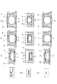
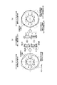
具体的には、図1〜図3に基づいて説明する。図1〜図3において、(a)、(b)、(c)は、それぞれ2ピースモールド法、第2セクショナルモールド法(セクター端面余肉無し法)、第1セクショナルモールド法(セクター端面余肉設定法)を示しており、左側部分には簡単な工程説明が付してある。 Specifically, it demonstrates based on FIGS. 1-3. 1 to 3, (a), (b), and (c) are respectively a two-piece molding method, a second sectional molding method (no sector end surface surplus method), and a first sectional mold method (sector end surface surplus). Setting method), and a simple process description is attached to the left side.
まず、鋳放し鋳物(リング鋳物)が製作される。この工程は前述した第1工程に該当するもので、 タイヤ成形金型用リング鋳物A1の意匠面部dの上下端部近傍の内径部に、後加工で除去出来、鋳放しで所定の直径で真円となることを狙った基準径部cを「鋳出し」にて付与しておく。これはマスターモデル又は鋳型形状の段階で作り込んでおく。図中、符号fは製品部である。 First, an as-cast (ring casting) is manufactured. This step corresponds to the first step described above, and can be removed by post-processing on the inner diameter portion in the vicinity of the upper and lower end portions of the design surface portion d of the ring casting A1 for a tire molding die. A reference diameter c intended to be a circle is given by “casting”. This is created at the stage of the master model or mold shape. In the figure, reference numeral f denotes a product part.
この基準径部cと、意匠面部dの内径が、狙い直径に対して、0.05〜0.2%(0.5/1000〜2.0/1000)程大きくなるようにリング鋳物A1を鋳造製作する(予め収縮率に設定しておくか、鋳型組立て直径の調整にて
対応しておく)もので、これは前述した第2工程に該当する。
The ring casting A1 is made so that the inner diameters of the reference diameter part c and the design surface part d are larger by 0.05 to 0.2% (0.5 / 1000 to 2.0 / 1000) than the target diameter. The casting is manufactured (the shrinkage rate is set in advance or the mold assembly diameter is adjusted), which corresponds to the second step described above.
リング鋳物A1は、2ピースモールド法(図1(a))と第2セクショナルモールド法(図1(b))については、基準径部c,意匠面部d共に、真円に近い形状となる為、鋳型の時点で基準径部cを意匠面部dと一体構造で製作しておくことができるが、第1セクショナルモールド法(図1(c))についてのみ、意匠面部dはセクターブロック単位で「花びら型」となる為、鋳型組立て時に、鋳型上下に真円狙いの基準径部cとなる別パーツ(ダミー)を付与して対応することが必要となる。 In the ring casting A1, the two-piece molding method (FIG. 1A) and the second sectional molding method (FIG. 1B) both have a shape close to a perfect circle in both the reference diameter portion c and the design surface portion d. The reference diameter portion c can be manufactured integrally with the design surface portion d at the time of casting, but only for the first sectional mold method (FIG. 1C), the design surface portion d is “ Since it becomes a “petal shape”, it is necessary to provide another part (dummy) to be a reference diameter portion c aimed at a perfect circle at the top and bottom of the mold when assembling the mold.
次は、中間加工工程で、これは前述した第3工程の前半部分に該当する。この工程では、タイヤ成形金型用リング鋳物A1の押湯部を切断除去してリング鋳物Aとし、背面形状を、あとから嵌め込む拘束リング10の内面形状と概略同形状に機械加工しておく。
Next is an intermediate processing step, which corresponds to the first half of the third step described above. In this step, the hot metal portion of the ring casting A1 for tire molding dies is cut and removed to form the ring casting A, and the back surface shape is machined to approximately the same shape as the inner surface shape of the restraining
次は、拘束リング設置工程で、これは前述した第3工程の後半部分に該当する。この工程では、 加工した背面部が、拘束リング10の内面に概略密着するように、タイヤ金型用リング鋳物Aを拘束リング10内に嵌め込む。なお、拘束リング10は、タイヤ金型用リング鋳物Aの材質より降伏強度が高く、かつ、熱膨脹率が小さい材質であることが必須である。
Next is a restraint ring installation process, which corresponds to the latter half of the third process described above. In this step, the tire mold ring casting A is fitted into the restraining
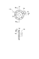
次は、図2に示す内径収縮止めリング設置工程で、これは前述した第4工程に該当する。この工程では、タイヤ金型用リング鋳物Aの基準径部cに、該当基準径部cでの狙い直径を外径寸法に持ち、ほぼ真円に加工された、熱膨脹率がタイヤ金型用リング鋳物Aのそれと同等もしくはそれ以下で、かつ、降伏強度特性が高い材質からなる、内径収縮止めリング11を嵌め込む。タイヤ金型用リング鋳物の意匠面部と基準径部は、第2工程で狙い直径より0.05〜0.2%程大きく作り込まれている為、内径収縮止めリング11を嵌め込むのには殆ど支障は無い。
Next is an inner diameter shrinkage prevention ring installation step shown in FIG. 2, which corresponds to the fourth step described above. In this step, the reference diameter part c of the ring mold A for the tire mold has the target diameter at the reference diameter part c as the outer diameter, and is processed into a substantially circular shape. An inner diameter
次に加熱保持工程および冷却工程で、前述した第5工程に該当する。図2中、加熱保持工程の符号12はヒータ、符号13は加熱炉である。この工程では、加熱時に、タイヤ金型用リング鋳物Aの方が、拘束リング10より大きな熱膨脹することから、拘束リング10に押し潰されると共にその後冷却する際に直径を小さくする方向に塑性変形することになる。この加熱時の塑性変形及び、冷却時のリング鋳物の冷却収縮でタイヤ金型用リング鋳物の内径が小さくなって行く際に、内径収縮止めリング11が存在していることから、リング鋳物Aの基準径部cが内径収縮止めリング11の外周部に接触した時点で、リング鋳物Aが、これ以上の内径収縮挙動を示すことは無くなると同時に、リング鋳物Aの内面真円度特性が、内径収縮止めリング11の外周部の真円度特性に倣って行くことになり、これにより直径矯正と真円度特性の改善効果を同時に得ることができる。
Next, the heating and holding step and the cooling step correspond to the fifth step described above. In FIG. 2,
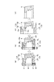
次は、図3に示す拘束リングおよび内径収縮止めリングの除去工程および外周加工工程で、これは前述した第6工程に該当する。この工程では、2ピースモールド法の場合は、上下型(製品部f)が製作され、型合わせによりタイヤ成形用金型が完成し、第2セクショナルモールド法の場合は、製品部fが製作され、その後の製品部fのセクター分割で分割されたセクターブロック(図示せず)の組立でタイヤ成形用金型が完成し、および第1セクショナルモールド法の場合は、リング鋳物Aの外周部分が加工され、その後のセクター分割および分割されたセクターの外周加工を経て得られるセクターブロックの組立でタイヤ成形用金型が完成する。 Next is a removal step and an outer periphery processing step of the restraining ring and the inner diameter shrinkage prevention ring shown in FIG. 3, which correspond to the sixth step described above. In this process, the upper and lower molds (product part f) are manufactured in the case of the two-piece molding method, the tire molding die is completed by mold matching, and the product part f is manufactured in the case of the second sectional molding method. After that, a tire molding die is completed by assembling sector blocks (not shown) divided by sector division of the product part f, and in the case of the first sectional molding method, the outer peripheral portion of the ring casting A is processed. Then, a tire molding die is completed by assembling sector blocks obtained through subsequent sector division and peripheral processing of the divided sectors.
このタイヤ成形用金型の製造方法によれば、予め内径を大き目(0.05〜0.2%程狙い直径より大き目)に製作しておいたタイヤ成形金型用リング鋳物Aの鋳出し基準径部cに、該当基準径部cの狙い直径を外径に持つ内径収縮止めリング11を嵌め込んだ状態で、熱間矯正(直径縮小矯正)を行うことで、リング鋳物Aの内径と真円度特性を同時に矯正できる点と、熱間矯正する際の条件設定を読み違えて、リング鋳物Aを内径縮小し過ぎるような条件となった場合でも、内径収縮止めリング11の存在で、それ以下の内径に縮小されることが無い点が、メリットとなっている。
According to this method for manufacturing a tire molding die, the casting standard of the ring casting A for a tire molding die that has been manufactured in advance with a large inner diameter (larger than the target diameter of 0.05 to 0.2%). By performing hot correction (diameter reduction correction) in a state in which the inner diameter
さらに、各工程毎に詳細に検討してみる。 Further, consider each process in detail.
まず、第1工程において、基準径部cを鋳出しで作り込んでおくのは、直径縮小矯正時に、この部分に内径収縮止めリング11を当て込んで、リング鋳物Aの内径,真円度特性を矯正する際に、多少の圧縮塑性変形を伴うため、仕上げ加工可能な仕上げ代を付与する必要があることから、意匠面では無く、タイヤ金型のサイドウォール(サイドプレート)と嵌合する面(意匠の無い円筒面もしくは円錐面)である、上下端部直近に配置することが作業上もっとも利便性が高いためである。
First, in the first step, the reference diameter portion c is formed by casting. The diameter
また、第2工程において、タイヤ金型用リング鋳物Aの基準径部c及び意匠面部dの内径を、狙い直径に対して0.05〜0.2%程大きく作り込んでおくのは、後の直径縮小矯正で真円度特性をも同時に矯正させるためである。 In the second step, the inner diameters of the reference diameter part c and the design surface part d of the ring casting A for tire molds are made larger by about 0.05 to 0.2% than the target diameter. This is because the roundness characteristic is corrected at the same time by the diameter reduction correction.
この範囲に設定したのは、0.05%以下では、矯正時にリング鋳物Aに充分な圧縮歪みを与えられず、バウシンガー効果を利用した真円度矯正効果が発揮されにくいこと、および0.2%以上では、矯正時にリング鋳物Aの円周方向の圧縮塑性変形させる量が大きくなり過ぎ座屈変形による真円度悪化が現われ易いことによる。 This range is set to 0.05% or less, because the ring casting A cannot be given sufficient compressive strain at the time of correction, and the roundness correction effect using the Bausinger effect is difficult to be exhibited. If it is 2% or more, the amount of the ring casting A subjected to compressive plastic deformation in the circumferential direction during correction becomes too large, and the roundness deterioration due to buckling deformation tends to appear.
また、第3工程において、拘束リング10の材質がタイヤ金型用リング鋳物の材質より降伏強度が高く、かつ熱膨張率が低いものである必要があるのは、加熱による熱膨脹量差を利用する為で、リング鋳物の方をより大きく熱膨脹させ拘束リング10で絞め込んでも、拘束リング10側は塑性変形させず、リング鋳物A側のみ塑性変形させる為である。 また、リング鋳物Aの背面を拘束リング10の内面形状に概略密着する形状に予め機械加工するのは、熱膨脹量差分でリング鋳物Aに生じる歪みエネルギーを極大化させ、効率よく直径縮小矯正させる為である。
Further, in the third step, the material of the restraining
また、第4工程において、タイヤ成形金型用リング鋳物Aの鋳出し(鋳放し)基準径部cへの内径収縮止めリング11の設置は、熱膨脹量差を利用した直径縮小矯正を行った時の従来法の次の問題点、
i. 加熱温度,加熱保持時間の設定等、熱間矯正条件の設定が難しく、狙いの直径に縮小するのに高度な予測技術を要する(複数回の熱間矯正を行う必要がある場合や、縮小し過ぎてしまう場合も存在する)こと、および
ii.真円度特性は基本的に改善しないこと、
を解消するためである。
Further, in the fourth step, the inner diameter shrinkage-preventing
i. It is difficult to set hot correction conditions such as setting of heating temperature and heating holding time, and advanced prediction technology is required to reduce to the target diameter (if multiple hot corrections are required, It may be too small), and
ii. The roundness characteristic is basically not improved,
This is to eliminate the problem.
また、内径収縮止めリング11の材質が、タイヤ金型用リング鋳物Aの材質と比べて、 熱膨脹率が同等か、それ以下である必要があるのは、熱間矯正時に、内径収縮止めリング11が熱膨脹しても、リング鋳物Aの基準径部cに接触しないようにすることを確実に保証するため(内径収縮止めリング11がリング鋳物Aを押し広げ、内径拡張させない為)であり、 降伏強度が高い必要があるのは、熱間矯正時(及び冷却中)にリング鋳物Aが内径収縮止めリング11に接触したとき以降で、リング鋳物Aの方を優先的に塑性変形させて真円度矯正させるためである。
Also, the material of the inner diameter
また、第5工程において、加熱保持する条件(熱間矯正条件)は、材質,代表直径,各部の肉厚等の変化で、微妙に変化する為、一義的に定義することはできないが、概略以下のようなものである。 In addition, in the fifth step, the heating and holding conditions (hot correction conditions) are subtly changed due to changes in the material, representative diameter, thickness of each part, etc., and therefore cannot be uniquely defined. It is as follows.
i.加熱温度は概ね、100〜400℃である。タイヤ金型用リング鋳物Aの対象となる材質は「アルミ合金」が圧倒的に多いため、これを想定した場合、100℃未満では、リング鋳物Aと拘束リング10間に充分な熱膨脹率差を持たせられない。すなわち、熱間矯正時にリング鋳物Aに充分な圧縮歪みエネルギーを投与できないため、内径縮小させられない。加熱によるリング鋳物Aの降伏強度低下も少ないため、圧縮塑性変形させづらいと言う理由もある。他方、400℃超では、熱間矯正後のリング鋳物Aの強度特性低下が著しくなり、また、拘束リング10,内径収縮止めリング11の酸化損傷も大きくなると言う問題が生じるためである。
i. The heating temperature is generally 100 to 400 ° C. Since the material which is the object of the ring casting A for tire molds is predominantly “aluminum alloy”, assuming this, if the temperature is less than 100 ° C., a sufficient difference in thermal expansion coefficient between the ring casting A and the restraining
ii.理論的に必要とされる加熱温度は、以下の式で算出できる。 ii. The heating temperature theoretically required can be calculated by the following equation.
T(℃)=25(室温:℃)+(φDA−φDF)/{(αP−αR)×φDA}
ここで、
αP : リング鋳物Aの室温から加熱温度までの熱膨脹率(%)
αR : 拘束リング10の室温から加熱温度までの熱膨脹率(%)
φDA : 矯正前のリング鋳物Aの基準径部cの内径(直径)
φDF : リング鋳物Aの基準径部cでの矯正後の狙い内径(直径)
実際には、リング鋳物Aと拘束リング10の熱膨脹量差で生まれる歪みエネルギーの内、リング鋳物Aの降伏歪みを超えた分だけが、リング鋳物Aの塑性変形につながることになるので、上記式で求められる理論加熱温度だけでは充分な矯正ができない場合が多い。このため、実際の加熱温度は、この数値Tプラス50〜100℃程度の値で設定することになる。
T (° C.) = 25 (room temperature: ° C.) + (ΦDA−φDF) / {(αP−αR) × φDA}
here,
αP: Thermal expansion rate (%) of ring casting A from room temperature to heating temperature
αR: Thermal expansion rate (%) of the restraining
φDA: Inner diameter (diameter) of the reference diameter c of the ring casting A before straightening
φDF: Target inner diameter (diameter) after correction at the reference diameter c of the ring casting A
Actually, the strain energy generated by the difference in thermal expansion between the ring casting A and the constraining
iii. 加熱時間は、矯正するリング鋳物Aの大きさ(内径,肉厚,高さ,重量)によっても異なる。リング鋳物A全体が、上記加熱温度まで上昇する時間が異なることが、この主な理由であるが、概略2〜12hrの加熱で一回の熱間矯正が完了できると言える。 iii. The heating time varies depending on the size (inner diameter, wall thickness, height, weight) of the ring casting A to be corrected. The main reason is that the entire ring casting A rises to the above heating temperature. This is the main reason, but it can be said that one hot correction can be completed by heating for approximately 2 to 12 hours.
また好ましくは、拘束リング10は、リング全体としてのヤング率を、拘束リング10の各部に穴を空けるか、あるいは拘束リング10を発泡金属や空隙率の高い焼結金属を用いて製作する等の手法で意図的に小さくし、タイヤ成形金型用リング鋳物Aのヤング率に近づけて製作される。
Further, preferably, the
タイヤ金型用リング鋳物の材質は、圧倒的にアルミ合金であることが多い。このため、拘束リング10の材質としては、鋼材を用いれば、安価に、タイヤ金型用リング鋳物Aより熱膨脹率が低く、降伏強度が高いと言う条件をクリアできる。
The material of ring castings for tire molds is predominantly an aluminum alloy. For this reason, if steel is used as the material of the
熱間矯正による直径縮小矯正におけるリング鋳物Aの直径縮小矯正過程では、リング鋳物Aと拘束リング10の熱膨脹量差によりリング鋳物Aに生じる(圧縮)歪みが、如何に効率良く、リング鋳物A全体を圧縮降伏させるか否かによって、矯正後のリング鋳物Aの内径寸法が決まると言える。
In the diameter reduction correction process of the ring casting A in the diameter reduction correction by the hot correction, the (cast) strain generated in the ring casting A due to the difference in thermal expansion between the ring casting A and the constraining
熱間矯正時のリング鋳物Aに生じる(圧縮)歪みは、リング鋳物Aと拘束リング10間の熱膨脹量差と、リング鋳物Aの直径、および、リング鋳物Aと拘束リング10のヤング率(縦弾性係数)により決定されると言える。リング鋳物Aのヤング率より拘束リング10のヤング率が大きい程、リング鋳物Aに生じる歪みは大きくなるが、この圧縮歪みはリング鋳物Aの外周面(拘束リング10との接触面)部でより顕著に集中してしまい、リング鋳物A内面に効率的に圧縮歪みが届きにくいと言う特性を持つ。
The (compression) strain generated in the ring casting A during hot straightening includes the difference in thermal expansion between the ring casting A and the constraining
したがって、熱間矯正時に、リング鋳物Aの外周部に生じる最大圧縮歪みが、過剰に大きすぎる状況が発生すると、この部位のみ優先的に塑性変形してしまい、リング鋳物Aで最も直径縮小させたい「意匠面(内面)」に歪みエネルギーが効率的に届かないと言う現象が生じることになる。 Therefore, when a situation occurs in which the maximum compressive strain generated in the outer peripheral portion of the ring casting A is excessively large during hot correction, only this portion is preferentially plastically deformed, and it is desired to reduce the diameter most in the ring casting A. A phenomenon occurs in which strain energy does not efficiently reach the “design surface (inner surface)”.
図4は、前記現象を説明するもので、リング鋳物A,拘束リング10のヤング率のバランスが良い場合を図中「G00d」で示してあり、そうでない場合、すなわちリング鋳物Aに対して拘束リング10のヤング率が高すぎる場合を「NG」で示してある。「G00d」の場合は、リング鋳物A全体がうまく圧縮塑性変形してリング鋳物Aの基準径部cが内径収縮止めリング11に接触するまで直径縮小するが、「NG」の場合は、リング鋳物A−拘束リング10の接触面部のみが優先的に圧縮塑性変形gしてしまいリング鋳物Aの基準径部c,及び意匠面部dが充分に直径縮小しきれない。
FIG. 4 illustrates the above phenomenon, and the case where the balance of the Young's modulus of the ring casting A and the constraining
このように、単に、リング鋳物Aの材質=アルミ合金,拘束リング10の材質=一般鋼材,と言う組み合わせでは、
アルミ合金のヤング率 ≒ 7000kgf/mm2 (68650MPa)
鋼材のヤング率 ≒ 21000kgf/mm2 (205900MPa)
殆どの場合このようになることから、図4の「NG」の状況が発現され易いと言う問題点が存在している。
Thus, in the combination of simply the material of ring casting A = aluminum alloy and the material of
Young's modulus of aluminum alloy ≒ 7000kgf / mm2 (68650MPa)
Young's modulus of steel ≒ 21000kgf / mm2 (205900MPa)
Since this is the case in most cases, there is a problem that the situation of “NG” in FIG.
そこで拘束リング10は、鋼材(鉄材)製であっても、顕微鏡組織的に発泡させたものを用いることで、ヤング率のみ低く押えた材質を用いて製作することができる。例えば、球状黒鉛鋳鉄(FCD450〜FCD700)のように、鋼材の金属結晶組織内部に、細かな「グラファイト(炭素:C)」が球状に分布しているような材質(ヤング率≒17000kgf/mm2)や、空隙率(ヤング率は空隙率で大きく変化する)の高い焼結金属を用い得る。
Therefore, even if the restraining
こうすることにより、拘束リング10は、安価で入手しやすい鋼材(鉄材)製であっても、そのヤング率をアルミ合金のそれに近づけることができ、これによりリング鋳物Aで最も直径縮小させたい「意匠面(内面)」に歪みエネルギーが効率的に届くことができ、リング鋳物Aの直径と真円度特性を一層確実に向上させることができる。
By doing so, even if the restraining
さらに好ましくは、内径収縮止めリング11は、2つ以上のパーツに分離可能な組立て構造体として製作される。
More preferably, the inner diameter
図5は、熱間矯正過程を説明するもので、熱間矯正前、熱間矯正後、および矯正治具取り外しの各状態を示している。 FIG. 5 illustrates the hot straightening process, and shows each state before hot straightening, after hot straightening, and removal of the straightening jig.
熱間矯正過程では、矯正時にリング鋳物Aに過剰に直径縮小歪みを作用させてしまう場合がある。この場合であっても、内径収縮止めリング11の存在のお陰でリング鋳物Aの内径は、狙い寸法に維持されることになるのであるが、矯正終了後の冷却時に、リング鋳物Aの材質の冷却収縮量が、内径収縮止めリング11の冷却収縮量を大幅に上回るケースが出てくる。
In the hot straightening process, a diameter reduction distortion may be excessively applied to the ring casting A during straightening. Even in this case, the inner diameter of the ring casting A is maintained at the target size due to the presence of the inner diameter
この時に、内径収縮止めリング11は、リング鋳物Aにより、あたかも「しまり嵌め」されたような状態となり、リング鋳物Aから内径収縮止めリング11を脱型することが困難となる場合が出てくる(図5中、「矯正治具取外し」参照)。
At this time, the inner diameter
この場合の内径収縮止めリング11の脱型を容易にするために、内径収縮止めリング11が、2つ以上のパーツに分離可能な組立て構造体として製作されるのである。
In order to facilitate the removal of the inner diameter
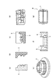
図6は、第1実施形態としての内径収縮止めリング11Aを示す。この内径収縮止めリング11Aは、外周に沿う薄肉帯状の爪収容部15を備えた円盤状の一枚のカム定盤14と、このカム定盤14の爪収容部15に半径方向に移動可能に収容される複数の可動爪16とで大略構成されている。可動爪16は、外端側が幅広の略扇形の平面を有し、内端側に可動斜面16aを有して形成されており、本実施形態では一枚のカム定盤14に対して8個用いられている。爪収容部15は、可動爪16の可動斜面16aが摺動可能に当接する固定斜面15aを内周に沿って形成することによって構成されている。図6中、符号17は、カム定盤14に穿設される締結孔である。
FIG. 6 shows an inner diameter
図7は、内径収縮止めリング11Aを用いて、内径縮小矯正(熱間矯正)を行い、室温まで冷却した状態からの、型バラシ工程を示している。図7(a)は、室温まで冷却した状態を示しており、上下の内径収縮止めリング11A、11Aは、締結孔17を透通する締結ボルトにより締結されている。この室温まで冷却した時点で、リング鋳物Aと内径収縮止めリング11Aとの間の冷却収縮量の差によって、内径収縮止めリング11Aに、内側の締付け力が発生した場合でも、図7(b)に示すように、締結ボルト18を緩めた時点で、固定斜面15aと可動斜面16aとの間の相互摺動による可動爪16のカム式スライド(矢印方向のカムアクション)により、リング鋳物Aの締付け歪みは開放され、図7(c)、(d)に示すように、楽に内径収縮止めリング11Aを脱型することが可能となる。なお、図7(b)において、符号A0は、締結ボルト18を緩める前のリング鋳物Aの位置を示している。
FIG. 7 shows a mold breaking process from a state in which the inner diameter reduction correction (hot correction) is performed using the inner diameter shrinkage-preventing
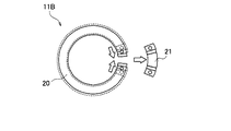
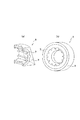
図8は、第2実施形態としての内径収縮止めリング11Bを示す。この内径収縮止めリング11Bは、2分割タイプのものであって、略C字形のリング本体20と、このリング本体20の両端を脱着可能に連結する脱着パーツ21とから構成されている。脱着パーツ21は、結合孔22に螺合されるボルト(図示せず)を介してリング本体20の両端に結合される。
FIG. 8 shows an inner diameter
そしてこの内径収縮止めリング11Bは、図9に示すように、脱着パーツ21をリング本体20から離脱することにより、リング本体20の直径縮小変形(破線から実線への変化)が容易となり、これによりリング鋳物からの脱型が容易に行われる。
As shown in FIG. 9, the inner diameter
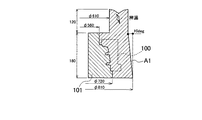
以下、実施例により、本発明をさらに具体的に説明する。図10は、以下の全ての実施例に共通して用いたタイヤ成形用金型100を示す。 Hereinafter, the present invention will be described more specifically with reference to examples. FIG. 10 shows a tire molding die 100 used in common for all the following examples.
このタイヤ成形用金型100は、タイヤサイズ205/65R15用の2Pモールドタイプのタイヤ成形用金型であり、以下の条件を備えている。 The tire molding die 100 is a 2P mold type tire molding die for tire size 205 / 65R15, and has the following conditions.
基本ピッチ種類 S,M,Lの3種類
ピッチ数 Sピッチ 11ヶ,Mピッチ 13ヶ,Lピッチ 12ヶ
サイプブレード鋳包み無し
図11は、鋳型101、鋳放しリング鋳物A1、およびタイヤ成形用金型100の相互関係を示しており、それぞれ以下の条件に従って形成される。
3 types of basic pitch types S, M, and L Number of pitches S pitch 11 pieces, M pitch 13 pieces, L pitch 12 pieces No sipe blade casting Figure 11 shows
金型の基本製法 : 石膏鋳造法
設定収縮率 11〜15/1000 (部位によって変化)
石膏鋳型材質 USG製 ハイドロパーム発泡石膏
混水率 70重量%,発泡増量 60%で調合したもの
鋳造用合金 AC4C合金 (7%Si,1%Cu,0.5%Fe,0.4%Mg,残Al)
鋳込み方法 重力鋳造(流し込み方式)
図10および図11の数値は、各部をmmで示すものであり(以下の図中においても同様である)、特に図11の上、下基準径部の直径数値は、意匠面部の直径を図10の意匠面部の正規寸法狙いで作り込んだ時の数値である。
Basic mold manufacturing method: Plaster casting method Set shrinkage ratio 11-15 / 1000 (varies depending on the part)
Gypsum mold material USG Hydro Palm Foam Gypsum
Mixed with 70% by weight water content and 60% foaming increase Casting alloy AC4C alloy (7% Si, 1% Cu, 0.5% Fe, 0.4% Mg, remaining Al)
Casting method Gravity casting (casting method)
The numerical values in FIG. 10 and FIG. 11 indicate each part in mm (the same applies to the following drawings). In particular, the numerical values in the upper and lower reference diameter parts in FIG. It is a numerical value when it is made with the aim of regular dimensions of 10 design surface portions.
(実施例1)
意匠面部の直径が、0.5mm(0.7/1000)ほど大きくなることを狙って鋳放しリング鋳物A1(図11参照)を製作した。
Example 1
An as-cast ring casting A1 (see FIG. 11) was manufactured with the aim of increasing the diameter of the design surface part by about 0.5 mm (0.7 / 1000).
この鋳放しリング鋳物A1の意匠面部の各部半径を、タイヤ幅方向で4等配 ,円周方向でほぼ72等配の計288箇所で測定した。その結果を表1に示す。

次に鋳放しリング鋳物A1の押湯部分を切断除去して、リング鋳物Aを製作する。そしてこのリング鋳物Aに対して、図12に示すように、「曲面R」を定義し、この形状でリング鋳物Aの背面を旋盤加工した後、該当加工面形状を内面に持つ、FCD600材(球状黒鉛鋳鉄材)製の肉厚50mmの拘束リング内に嵌め込む。このときリング鋳物Aの上、下基準径部cには、それぞれ外径φ560mm,720mmで肉厚20mmのS50C(鋼材)製の一体構造の内径収縮止めリングをセットした状態で、加熱炉に投入し(図2の「加熱保持工程」参照)、250℃で5時間保持し内径縮小矯正を行った。その後、炉から取り出し、空冷後、拘束リング,内径収縮止めリングを取り外し、リング鋳物Aを回収した。 尚、内径収縮止めリングの外周部にはボロンナイトライド系の離型剤を塗布しておき、滑りやすい状態にしておいた。 Next, the ring casting A is manufactured by cutting and removing the feeder portion of the as-cast ring casting A1. Then, for this ring casting A, as shown in FIG. 12, a “curved surface R” is defined, and after turning the back surface of the ring casting A in this shape, the FCD600 material (with the corresponding machining surface shape on the inner surface) ( It is fitted into a restraining ring made of (spheroid graphite cast iron material) having a thickness of 50 mm. At this time, in the upper and lower reference diameter portions c of the ring casting A, an inner diameter shrinkage prevention ring made of S50C (steel) having an outer diameter of 560 mm and 720 mm and a wall thickness of 20 mm is set in the heating furnace. (Refer to “Heat-holding step” in FIG. 2), and held at 250 ° C. for 5 hours to reduce the inner diameter. Thereafter, the ring was taken out of the furnace and cooled with air, and then the restraining ring and the inner diameter shrinkage prevention ring were removed, and the ring casting A was recovered. A boron nitride release agent was applied to the outer peripheral portion of the inner diameter shrinkage stop ring so that it was slippery.
このようにして得られたリング鋳物Aの意匠面部の各部半径の特性を表2にまとめた。このときの測定ポイントは、矯正前の鋳放しリング鋳物A1の測定とほぼ同じ部位とした。
表1および表2から明らかなように、リング鋳物Aは、その直径,真円度,クラウンR形状の全てについて鋳放し状態A1より向上させることができ、ひいてはこれら要件に対して高精度のタイヤ成形用金型を製作できることが理解できる。 As is apparent from Tables 1 and 2, the ring casting A can be improved from the as-cast state A1 with respect to all of its diameter, roundness and crown R shape. It can be understood that a molding die can be manufactured.
(実施例2)
意匠面部の直径が、0.5mm(0.7/1000)ほど大きくなることを狙って鋳放しリング鋳物A1(図11参照)を製作した。
(Example 2)
An as-cast ring casting A1 (see FIG. 11) was manufactured with the aim of increasing the diameter of the design surface part by about 0.5 mm (0.7 / 1000).
この鋳放しリング鋳物A1の意匠面部の各部半径を、タイヤ幅方向で4等配 ,円周方向でほぼ72等配の計288箇所で測定した。その結果を表3に示す。
次に鋳放しリング鋳物A1の押湯部分を切断除去してリング鋳物A(図12参照)とし、このリング鋳物Aを実施例1と同様に外周加工を行い、拘束リング内に嵌め込む。その後、リング鋳物Aの上、下基準径部c(図12参照)には、それぞれ外径φ560mm,720mmで肉厚30mmのS50C製の、リング本体20と脱着パーツ21とを備えた2分割タイプの内径収縮止めリング11B(図13参照)をセットした状態で、加熱炉に投入し、350℃で5時間保持した。その後、炉から取り出し、空冷後、拘束リング,内径収縮止めリング11Bを取り外した。この際、内径収縮止めリング11Bは、リング鋳物Aに抱き込まれた状態で、組立て状態では脱型が困難であった為、脱着パーツ21を取り外した後、リング本体20を直径縮小させて脱型した。
Next, the hot metal portion of the as-cast ring casting A1 is cut and removed to form a ring casting A (see FIG. 12), and this ring casting A is subjected to outer periphery processing in the same manner as in Example 1 and fitted into the restraining ring. Thereafter, the upper and lower reference diameter portions c (see FIG. 12) on the ring casting A are divided into two types, each having an outer diameter φ560 mm, 720 mm, and a
このようにして得られたリング鋳物Aの意匠面部の各部半径の特性を表4にまとめた。このときの測定ポイントは、矯正前の鋳放しリング鋳物A1の測定とほぼ同じ部位とした。
表3および表4から明らかなように、実施例2では実施例1の場合より、直径縮小量を大きくとったことで、矯正時の各部直径,真円度矯正効果がより大きく発揮される形となった。すなわち、真円度,クラウンR形状精度が、実施例1より向上した。 As is apparent from Tables 3 and 4, in Example 2, the diameter reduction amount is larger than that in Example 1, so that the effect of correcting the diameter and roundness of each part at the time of correction is more greatly exhibited. It became. That is, the roundness and the crown R shape accuracy were improved as compared with the first embodiment.
また、こうした時の問題点である、空冷後の内径収縮止めリング11Bのリング鋳物からの脱型困難さも、2分割構造の内径収縮止めリング11Bを用いることで回避することができた。
In addition, the difficulty in removing the inner diameter
(比較例1)
意匠面部の直径が、0.5mm(0.7/1000)ほど大きくなることを狙って鋳放しリング鋳物A1(図11参照)を製作した。
(Comparative Example 1)
An as-cast ring casting A1 (see FIG. 11) was manufactured with the aim of increasing the diameter of the design surface part by about 0.5 mm (0.7 / 1000).
この鋳放しリング鋳物A1の意匠面部の各部半径を、タイヤ幅方向で4等配 ,円周方向でほぼ72等配の計288箇所で測定した。その結果を表5に示す。
この鋳放しリング鋳物A1を、基本的に実施例2と同じ条件で直径縮小矯正した。 This as-cast ring casting A1 was subjected to diameter reduction correction under basically the same conditions as in Example 2.
但し、本比較例1で使用した拘束リングの材質は、S50C(鋼材)とした。 However, the material of the restraint ring used in this Comparative Example 1 was S50C (steel material).
直径縮小矯正後のリング鋳物A(図12参照)の意匠面部の各部半径の特性を表6にまとめた。このときの測定ポイントは、矯正前の鋳放しリング鋳物A1の測定とほぼ同じ部位とした。
表5および表6から明らかなように、比較例1の真円度,クラウンR形状精度の結果が、実施例2の結果より悪くなったのは、比較例1の方が、拘束リングのヤング率が高く(実施例2の拘束リングのヤング率≒16000kgf/mm2に対し比較例1の拘束リングのヤング率≒21000kgf/mm2)、熱間矯正時にリング鋳物Aに作用する歪みエネルギーが、リング鋳物Aの背面に局部的に集中し易くなり、リング鋳物Aの背面側の局部変形と言う形で、その一部が消費されてしまったためと思われる。 As is clear from Tables 5 and 6, the results of the roundness and crown R shape accuracy of Comparative Example 1 were worse than the results of Example 2. The rate is high (Young's modulus of the constraining ring of Example 2≈16000 kgf / mm 2 versus Young's modulus of the constraining ring of Comparative Example 1≈21000 kgf / mm 2 ), and the strain energy acting on the ring casting A during hot straightening is It seems that it becomes easy to concentrate locally on the back surface of the ring casting A, and a part thereof is consumed in the form of local deformation on the back surface side of the ring casting A.
10 拘束リング
11 内径収縮止めリング
11A 内径収縮止めリング
11B 内径収縮止めリング
13 加熱炉
14 カム定盤(パーツ)
16 可動爪(パーツ)
20 リング本体(パーツ)
21 脱着パーツ(パーツ)
100 タイヤ成形用金型
A リング鋳物
c 基準径部
d 意匠面部
10
16 movable claws (parts)
20 Ring body (parts)
21 Detachable parts (parts)
100 Tire Mold A A Ring Casting c Reference Diameter Part d Design Surface Part
Claims (3)
リング鋳物状態で上下端直近の内径部に後加工で除去でき、所定の直径の真円となることを狙った基準径部を鋳出しにより形状製作する第1工程と、
前記基準径部と意匠面部の内径が、狙い直径に対して0.05〜0.2%程度大きくなるようにタイヤ成形金型用リング鋳物を、鋳造、製作する第2工程と、
前記タイヤ成形金型用リング鋳物の外周部を、直径縮小矯正で用いる拘束リングの内径と概略同じ直径になるように機械加工した後、前記タイヤ成形金型用リング鋳物を拘束リング内に嵌め込む第3工程と、
前記基準径部に、同基準径部の狙い直径と概略同じ外径を持つように可能な限り真円に近い状態で加工された、熱膨脹率が前記タイヤ成形金型用リング鋳物の材質の熱膨脹率と同等もしくはそれ以下で、かつ、降伏強度特性の高い材質からなる内径収縮止めリングを嵌め込む第4工程と、
この状態で加熱炉内で加熱保持すると共にその後冷却することで、前記タイヤ成形金型用リング鋳物を圧縮降伏させ、前記タイヤ成形金型用リング鋳物の基準径部,意匠面部を所定の内径とすると同時に、その真円度特性も内径収縮止めリングの真円度特性に準ずる形に矯正する第5工程と、
前記拘束リングおよび内径収縮止めリングを、前記タイヤ成形金型用リング鋳物から除去すると共に除去後のリング鋳物を外周加工する第6工程とを順次経ることを特徴とする、タイヤ成形用金型の製造方法。 A method of manufacturing a tire molding die manufactured by a casting method,
A first step of producing a shape by casting a reference diameter portion that can be removed by post-processing to the inner diameter portion in the ring casting state and immediately close to the upper and lower ends, and becomes a perfect circle of a predetermined diameter;
A second step of casting and manufacturing a ring casting for a tire molding die so that the inner diameter of the reference diameter portion and the design surface portion is about 0.05 to 0.2% larger than the target diameter;
After machining the outer periphery of the ring molding for tire molding mold so as to have the same diameter as the inner diameter of the restraining ring used for diameter reduction correction, the ring casting for tire molding mold is fitted into the restraining ring. A third step;
The thermal expansion coefficient of the ring casting material for the tire molding die is processed in a state as close to a perfect circle as possible so that the reference diameter portion has an outer diameter substantially the same as the target diameter of the reference diameter portion. A fourth step of fitting an inner diameter shrinkage-preventing ring made of a material equivalent to or less than the rate and having a high yield strength characteristic;
In this state, the ring casting for tire molding die is compressed and yielded by heating and holding in the heating furnace and then cooling, and the reference diameter portion and the design surface portion of the ring casting for tire molding die are set to a predetermined inner diameter. And at the same time, the fifth step of correcting the roundness characteristic to a shape that conforms to the roundness characteristic of the inner diameter shrinkage prevention ring,
A tire molding die characterized by sequentially passing through a sixth step of removing the constraining ring and the inner diameter shrinkage-preventing ring from the ring casting for tire molding die and processing the outer periphery of the ring casting after removal. Production method.
前記拘束リングは、リング全体としてのヤング率を、意図的に小さくし、前記タイヤ成形金型用リング鋳物のヤング率に近づけて製作されることを特徴とする、タイヤ成形用金型の製造方法。 A method for manufacturing a tire molding die according to claim 1,
The method for producing a mold for molding a tire is characterized in that the restraint ring is manufactured by intentionally reducing the Young's modulus of the ring as a whole and approaching the Young's modulus of the ring molding for a tire mold. .
前記内径収縮止めリングは、2つ以上のパーツに分離可能な組立て構造体として製作されていることを特徴とする、タイヤ成形用金型の製造方法。 A method for producing a tire molding die according to claim 1 or 2,
The method for manufacturing a tire molding die, wherein the inner diameter shrinkage prevention ring is manufactured as an assembly structure separable into two or more parts.
Priority Applications (1)
| Application Number | Priority Date | Filing Date | Title |
|---|---|---|---|
| JP2003400374A JP4268024B2 (en) | 2003-11-28 | 2003-11-28 | Tire molding mold manufacturing method and tire molding mold |
Applications Claiming Priority (1)
| Application Number | Priority Date | Filing Date | Title |
|---|---|---|---|
| JP2003400374A JP4268024B2 (en) | 2003-11-28 | 2003-11-28 | Tire molding mold manufacturing method and tire molding mold |
Publications (2)
| Publication Number | Publication Date |
|---|---|
| JP2005161565A JP2005161565A (en) | 2005-06-23 |
| JP4268024B2 true JP4268024B2 (en) | 2009-05-27 |
Family
ID=34724663
Family Applications (1)
| Application Number | Title | Priority Date | Filing Date |
|---|---|---|---|
| JP2003400374A Expired - Fee Related JP4268024B2 (en) | 2003-11-28 | 2003-11-28 | Tire molding mold manufacturing method and tire molding mold |
Country Status (1)
| Country | Link |
|---|---|
| JP (1) | JP4268024B2 (en) |
Families Citing this family (4)
| Publication number | Priority date | Publication date | Assignee | Title |
|---|---|---|---|---|
| JP4789241B2 (en) * | 2005-11-29 | 2011-10-12 | 日本碍子株式会社 | Tire mold casting method |
| JP2012176756A (en) * | 2012-06-22 | 2012-09-13 | Toyo Tire & Rubber Co Ltd | Pneumatic tire |
| JP2018187655A (en) * | 2017-05-09 | 2018-11-29 | 株式会社ブリヂストン | Method for producing molding mold for tire |
| CN113561545B (en) * | 2021-06-18 | 2023-04-18 | 赛轮(沈阳)轮胎有限公司 | Improvement method for ensuring rationalization of distribution of tire bead bottom materials |
-
2003
- 2003-11-28 JP JP2003400374A patent/JP4268024B2/en not_active Expired - Fee Related
Also Published As
| Publication number | Publication date |
|---|---|
| JP2005161565A (en) | 2005-06-23 |
Similar Documents
| Publication | Publication Date | Title |
|---|---|---|
| CN100509352C (en) | Hot forming tool | |
| JP4676509B2 (en) | Mold for tire | |
| EP1380398B1 (en) | Method of manufacturing tire mold | |
| US20040139610A1 (en) | Method for manufacturing aluminum alloy wheel | |
| CN112792274A (en) | Arc-shaped aluminum hoop, mold for producing hoop and process method for producing hoop | |
| JP4268024B2 (en) | Tire molding mold manufacturing method and tire molding mold | |
| CN106488816A (en) | Manufacturing method of forged crankshaft | |
| NO743863L (en) | ||
| US8714953B2 (en) | Method of manufacturing mold for tire vulcanization and mold for tire vulcanization | |
| WO2007018063A1 (en) | Mold for die casting, method of manufacturing mold for die casting, and method for die casting | |
| JP3667723B2 (en) | Manufacturing method of tire mold | |
| JP2010046902A (en) | Method of manufacturing tire vulcanizing mold | |
| JP4301510B2 (en) | Manufacturing method of tire mold | |
| KR20110020275A (en) | Method of manufacturing the rotor | |
| JP3062096B2 (en) | Aggregate, mold for molding tire using the same, and method for producing them | |
| CN114226617A (en) | Production process of arc-shaped aluminum hoop | |
| CN214866961U (en) | Arc aluminium matter staple bolt and mould of production staple bolt | |
| CN110052595B (en) | Automobile steering knuckle with anti-transgranular fracture failure mode and manufacturing method thereof | |
| JP2004195544A (en) | Sizing mold, method for forming crankshaft base material, and method for manufacturing crankshaft | |
| JP3746828B2 (en) | Manufacturing method for cylindrical parts | |
| JP3895309B2 (en) | Manufacturing method of tire molding die and tire molding die manufactured by the manufacturing method | |
| JP3806091B2 (en) | Manufacturing method of tire mold | |
| JP2000197945A (en) | Deburring device for crankshaft forgings | |
| JP2003019534A (en) | Forging method of circular material | |
| JPH1190568A (en) | Manufacture of ring gear, die for manufacturing ring gear, and manufacture of die |
Legal Events
| Date | Code | Title | Description |
|---|---|---|---|
| A621 | Written request for application examination |
Free format text: JAPANESE INTERMEDIATE CODE: A621 Effective date: 20060825 |
|
| A977 | Report on retrieval |
Free format text: JAPANESE INTERMEDIATE CODE: A971007 Effective date: 20080826 |
|
| A131 | Notification of reasons for refusal |
Free format text: JAPANESE INTERMEDIATE CODE: A131 Effective date: 20081104 |
|
| A521 | Written amendment |
Free format text: JAPANESE INTERMEDIATE CODE: A523 Effective date: 20081120 |
|
| TRDD | Decision of grant or rejection written | ||
| A01 | Written decision to grant a patent or to grant a registration (utility model) |
Free format text: JAPANESE INTERMEDIATE CODE: A01 Effective date: 20090127 |
|
| A01 | Written decision to grant a patent or to grant a registration (utility model) |
Free format text: JAPANESE INTERMEDIATE CODE: A01 |
|
| A61 | First payment of annual fees (during grant procedure) |
Free format text: JAPANESE INTERMEDIATE CODE: A61 Effective date: 20090219 |
|
| R150 | Certificate of patent or registration of utility model |
Free format text: JAPANESE INTERMEDIATE CODE: R150 |
|
| FPAY | Renewal fee payment (event date is renewal date of database) |
Free format text: PAYMENT UNTIL: 20120227 Year of fee payment: 3 |
|
| LAPS | Cancellation because of no payment of annual fees |