JP4279727B2 - Electric steering lock device - Google Patents
Electric steering lock device Download PDFInfo
- Publication number
- JP4279727B2 JP4279727B2 JP2004172625A JP2004172625A JP4279727B2 JP 4279727 B2 JP4279727 B2 JP 4279727B2 JP 2004172625 A JP2004172625 A JP 2004172625A JP 2004172625 A JP2004172625 A JP 2004172625A JP 4279727 B2 JP4279727 B2 JP 4279727B2
- Authority
- JP
- Japan
- Prior art keywords
- lock
- target
- bar
- steering lock
- actuator
- Prior art date
- Legal status (The legal status is an assumption and is not a legal conclusion. Google has not performed a legal analysis and makes no representation as to the accuracy of the status listed.)
- Expired - Fee Related
Links
- 238000001514 detection method Methods 0.000 claims description 13
- 238000000034 method Methods 0.000 claims description 12
- 230000008569 process Effects 0.000 claims description 6
- 238000012795 verification Methods 0.000 description 17
- 230000005540 biological transmission Effects 0.000 description 7
- 230000004043 responsiveness Effects 0.000 description 4
- 238000010586 diagram Methods 0.000 description 3
- 230000009467 reduction Effects 0.000 description 3
- 230000004044 response Effects 0.000 description 3
- 230000006872 improvement Effects 0.000 description 2
- 230000008859 change Effects 0.000 description 1
- 230000000694 effects Effects 0.000 description 1
- 230000003287 optical effect Effects 0.000 description 1
- 230000002093 peripheral effect Effects 0.000 description 1
Images
Landscapes
- Lock And Its Accessories (AREA)
Description
本発明は、ステアリングをロック状態又はアンロック状態に切り換える電動ステアリングロック装置に関するものである。 The present invention relates to an electric steering lock device that switches a steering to a locked state or an unlocked state.
近年、車両の操作性向上を目的として、機械的なキー操作をすることなく車両の各種動作を行うシステムが開発されている。そのシステムの1つに電子キーシステムがある。電子キーシステムとはユーザ(運転者)が電子キーを携帯してドアに近づけばドアロックが解錠され、遠ざかれば施錠されるキーレスエントリ機能や、キーをシリンダに差し込まなくてもイグニッションスイッチを回せばエンジンが始動するイグニッション機能等を備えたシステムである。 In recent years, systems for performing various operations of a vehicle without mechanical key operations have been developed for the purpose of improving the operability of the vehicle. One such system is an electronic key system. The electronic key system is a keyless entry function that unlocks the door lock when the user (driver) carries the electronic key close to the door and locks when the user moves away, and an ignition switch without inserting the key into the cylinder. This system has an ignition function that starts the engine when it is turned.
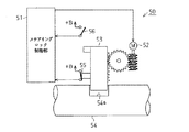
この種のシステムでは機械的なキー操作が行われないので、電気式に駆動する電動ステアリングロック装置を用いてステアリングをロック又はアンロックする必要がある。図4に示すように、ステアリングロック50は、同装置を動作させるロック制御部51がステアリングロックモータ52を駆動することによってロックバー53をストロークさせ、ロックバー53がステアリングシャフト54の凹部54aに係脱した状態となることで、施錠状態又は解除状態となる。
Since this type of system does not perform any mechanical key operation, it is necessary to lock or unlock the steering using an electrically driven electric steering lock device. As shown in FIG. 4, in the
ロック制御部51は、ステアリングロックモータ52を一方向に回してステアリングロック50を施錠状態にするとき、ロックバー53がステアリングシャフト54の凹部54aに係止した状態となってロックスイッチ55からオン信号を入力すると、ステアリングロックモータ52を停止する。一方、ロック制御部51は、ステアリングロックモータ52を他方向に回してステアリングロック50を解除状態にするとき、ロックバー53が凹部54aから離脱した状態となってアンロックスイッチ56からオン信号を入力すると、ステアリングロックモータ52を停止する。
When the
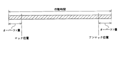
しかしながら、施錠動作時や解除動作時におけるステアリングロックモータ52の停止は、ロックスイッチ55又はアンロックスイッチ56がロックバー53を検出してから行われる。ところで、ステアリングロックモータ52に停止指令を出しても、ステアリングロックモータ52は直ぐに停止するわけではなく、慣性等が原因で若干回転した後に止まる。このため、ロックスイッチ55又はアンロックスイッチ56でロックバー53を検出してからステアリングロックモータ52を停止する方法をとると、図5に示すようにロックバー53がロック位置又はアンロック位置からオーバーランした位置で停止する。
However, the
このようにロックバー53がオーバーランすると、そのオーバーラン量だけステアリングロック50の作動時間が長くなる。ステアリングロック50は作動最中、ステアリングロックモータ52が動いたりロックバー53がストロークしたりすることで作動音が生じた状態となる。従って、ステアリングロック50の作動時間が長くなると、その分だけ作動音が長い時間発生することになるので、作動音発生時間を短くするためにオーバーラン量をなるべく少なくしたい要望があった。
When the
また、車両においてはステアリングロック50の動作が完了した後、例えばエンジン始動等の他の動作に移行する。ここで、ロックバー53がオーバーランすると、ステアリングロック50施錠又は解除が実際には完了しているにも拘らず、ステアリングロック50を余分に作動させることになり、その分だけ次の制御に移るまでにタイムロスが生じてしまう。従って、ロックバー53のオーバーラン量をできるだけ少なく抑えて、ステアリングロック50の応答性を高めたい要望もあった。
Further, in the vehicle, after the operation of the
本発明の目的は、ロックバーをロック位置やアンロック位置で止める際のオーバーラン量を少なく抑えることができる電動ステアリングロック装置を提供することにある。 An object of the present invention is to provide an electric steering lock device that can suppress an overrun amount when a lock bar is stopped at a lock position or an unlock position.
上記問題点を解決するために、請求項1に記載の発明では、ロックバーがアクチュエータによって往動することでステアリングロックが施錠状態となり、前記ロックバーが前記アクチュエータによって復動することで前記ステアリングロックが解除状態となる電動ステアリングロック装置において、アンロック位置又はロック位置から動き始めた前記ロックバーを目標停止位置で止めるべく、該ロックバーが前記目標停止位置に到達する前にアクチュエータを見切り停止させる際の基準の時間として目標時間を記憶した記憶手段と、前記ステアリングロックが施錠状態及び解除状態の少なくとも一方となる際に、前記ロックバーが移動を開始してからの経過時間を計時する計時手段と、前記経過時間と前記目標時間とを比較し、前記経過時間が前記目標時間に到達したときに前記アクチュエータに停止指令を出力して、前記ロックバーを見切り停止させる制御手段とを備えたことを要旨とする。
In order to solve the above problem, in the invention according to
この発明によれば、オーバーラン量の少ない目標停止位置でロックバーを止め得る目標時間を記憶手段に記憶しておく。そして、ステアリングロックが作動したとき、ロックバーがアンロック位置からロック位置、又はロック位置からアンロック位置へ移動するが、移動を開始してからのロックバーの経過時間を計時手段が計時する。このとき、経過時間と目標時間とを制御手段が逐次比較し、経過時間が目標時間に到達すると制御手段がアクチュエータに停止指令を出力し、これによってアクチュエータが停止してロックバーの移動が止まる。 According to the present invention, the target time for stopping the lock bar at the target stop position with a small overrun amount is stored in the storage means. When the steering lock is activated, the lock bar moves from the unlock position to the lock position, or from the lock position to the unlock position, and the time measuring means keeps track of the elapsed time of the lock bar since the movement is started. At this time, the control means sequentially compares the elapsed time and the target time, and when the elapsed time reaches the target time, the control means outputs a stop command to the actuator, thereby stopping the actuator and stopping the movement of the lock bar.
従って、ロックバーの経過時間が目標時間に到達したときにアクチュエータが停止する、つまりロックバーが目標停止位置で停止するようにアクチュエータが見切り停止するので、ロックバーが目標停止位置付近で止まることになり、ロックバーがロック位置やアンロック位置で止まる際のオーバーラン量を低く抑えることが可能となる。このため、オーバーラン量が多いことに起因するステアリングロックの作動時間長期化が抑えられ、作動音発生時間の低減化、ステアリングロック作動後の次の制御へ移る際の応答性が高まる。 Therefore, when the elapsed time of the lock bar reaches the target time, the actuator stops, that is, the actuator stops so that the lock bar stops at the target stop position, so that the lock bar stops near the target stop position. Thus, the overrun amount when the lock bar stops at the lock position or the unlock position can be kept low. For this reason, the operation time of the steering lock due to the large overrun amount is suppressed, the operation sound generation time is reduced, and the responsiveness when moving to the next control after the steering lock operation is increased.
請求項2に記載の発明では、請求項1に記載の発明において、前記見切り停止は、前記ステアリングロックの施錠時と解除時との両方で実施され、前記目標時間は、前記ロックバーがアンロック位置から前記目標停止位置としてのロック位置に移動する際と、前記ロックバーがロック位置から前記目標停止位置としてのアンロック位置に移動する際とで同じ値をとることを要旨とする。 According to a second aspect of the present invention, in the first aspect of the present invention, the parting stop is performed both when the steering lock is locked and when the steering lock is unlocked, and the lock bar unlocks the target time. The gist is that the same value is taken when moving from the position to the lock position as the target stop position and when the lock bar moves from the lock position to the unlock position as the target stop position .
この発明によれば、請求項1に記載の発明の作用に加え、ステアリングロックを施錠状態にするときと解除状態にするときとの両方で、ロックバーのオーバーラン量を少なく抑えることが可能となる。従って、作動音発生時間の低減化、ステアリングロック作動後の次の制御へ移る際の応答性向上化に一層寄与する。
According to the present invention, in addition to the operation of the invention described in
請求項3に記載の発明では、請求項1又は2に記載の発明において、前記ロックバーが前記目標停止位置に到達したことを検出する位置検出手段と、前記制御手段が前記アクチュエータに停止指令を出力して前記ロックバーの移動を停止させた際に、前記位置検出手段の検出信号に基づき前記ロックバーの停止位置が前記目標停止位置に到達していないと判断したとき、前記アクチュエータを再駆動する再駆動手段とを備え、前記再駆動手段は、前記アクチュエータを再駆動するとき、再駆動を行う前の通常時における前記ロックバーの移動速度よりも低い速度で前記ロックバーを移動させることを要旨とする。 According to a third aspect of the present invention, in the first or second aspect of the present invention, position detection means for detecting that the lock bar has reached the target stop position, and the control means sends a stop command to the actuator. When the movement of the lock bar is stopped by outputting, when it is determined that the stop position of the lock bar has not reached the target stop position based on the detection signal of the position detection means, the actuator is re-driven. Re-driving means, and when re-driving the actuator, the re-driving means moves the lock bar at a speed lower than the movement speed of the lock bar at a normal time before re-driving. The gist.
この発明によれば、請求項1又は2に記載の発明の作用に加え、ロックバー移動開始後の経過時間が目標時間に到達してアクチュエータの駆動が止められたとき、位置検出手段の検出信号に基づき再駆動手段がロックバーの停止位置を確認する。このとき、ロックバーの停止位置が目標停止位置に到達していなければ、再駆動手段がアクチュエータを再駆動してロックバーを目標停止位置へ移動させる。従って、最初の駆動で何らかの要因によってロックバーが目標停止位置に到達していなくても、アクチュエータを再駆動することによってロックバーを目標停止位置まで動かすことが可能となる。
According to this invention, in addition to the operation of the invention described in
請求項4に記載の発明では、請求項3に記載の発明において、前記アクチュエータの再駆動時、動き始めた前記ロックバーが前記目標停止位置で止まるまでに要する第2目標時間を記憶した第2記憶手段を備え、前記再駆動手段は、前記アクチュエータの再駆動時、再駆動時の経過時間と前記第2目標時間とを比較し、再駆動時の経過時間が前記第2目標時間に到達すると前記アクチュエータに停止指令を出力して前記ロックバーの移動を停止させ、前記ロックバーが前記目標停止位置に到達していないと判断すれば前記アクチュエータを再々駆動し、これら処理を前記ロックバーが前記目標停止位置に到達するまで繰り返し行うことを要旨とする。
In the invention described in
請求項5に記載の発明では、請求項4に記載の発明において、前記第2目標時間は、段階的な値を有するように前記第2記憶手段に複数記憶され、前記再駆動手段は、前記アクチュエータの再駆動時、最も値の大きい前記第2目標時間を用いて前記アクチュエータを再駆動し、それでも前記ロックバーが前記目標停止位置に到達していないと判断すれば、次に値の大きい前記第2目標時間を用いて前記アクチュエータを再々駆動し、これら処理を前記ロックバーが前記目標停止位置に到達するまで繰り返し行うことを要旨とする。 According to a fifth aspect of the present invention, in the fourth aspect of the present invention , a plurality of the second target times are stored in the second storage means so as to have stepwise values, and the re-driving means When the actuator is re-driven, the actuator is re-driven using the second target time having the largest value, and if it is still determined that the lock bar has not reached the target stop position, the next largest value is The gist is that the actuator is driven again using the second target time, and these processes are repeated until the lock bar reaches the target stop position .
本発明によれば、ロックバーをロック位置やアンロック位置で止める際のオーバーラン量を少なく抑えることができる。 According to the present invention, it is possible to reduce the amount of overrun when the lock bar is stopped at the lock position or the unlock position.
以下、本発明を具体化したで電動ステアリングロック装置の一実施形態を図1及び図2に従って説明する。
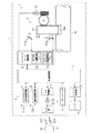
図1は、電子キーシステムの概略構成を示す構成図である。車両1は、イグニッションキーを用いずに各種車両操作が可能な電子キーシステム2を備えている。この電子キーシステム2では、電子キー3の持つIDコードが車両1のIDコードと一致すれば、キー操作を行うことなく車両1の各種動作が許可・開始される。車両1の各種動作としては、ドアの施錠・解錠、ステアリングの施錠・解錠、エンジンの始動、ラッゲージの開操作等がある。
Hereinafter, an embodiment of the electric steering lock device according to the present invention will be described with reference to FIGS. 1 and 2.
FIG. 1 is a configuration diagram showing a schematic configuration of an electronic key system. The
電子キーシステム2は、電子キー3との間でID照合を行う照合制御部4と、ドアロック5を制御するドア制御部6と、ステアリングロック7を制御するステアリングロック制御部8と、エンジン9を制御するエンジン制御部10とを備えている。また、電子キーシステム2は、照合制御部4の指令に基づき室外で電子キー3と信号のやり取りを行う室外送受信部11と、同じく照合制御部4の指令に基づき室内で電子キー3と信号のやり取りを行う室内送受信部12とを備えている。なお、ステアリングロック制御部8が制御手段、再駆動手段及び設定手段を構成する。
The
車両1が駐車状態(エンジン停止でドアが施錠状態)のとき、照合制御部4は室外送受信部11及びその室外アンテナ11aを介してリクエスト信号Sreを間欠的に発信させる。電子キー3の所有者がリクエスト信号Sreの通信エリアに入り込むと、電子キー3はリクエスト信号Sreに応答して、キー固有のIDコードを乗せたID信号Sidを発信する。照合制御部4は車両固有のIDコードを記憶しており、室外アンテナ11a及び室外送受信部11を介してID信号Sidを受信すると、電子キー3のIDコードと車両1のIDコードとを比較することで室外照合(ID照合)を実施する。室外照合が成立すれば、照合制御部4はドア制御部6に解除指令を出力し、ドア制御部6は解除指令に基づきドアロックモータ13を駆動してロック部14を解除状態にする。
When the
一方、ドアロック5が解除状態で室外照合が成立しているとき、照合制御部4はアンテナ11a及び室外送受信部11でID信号Sidを受信しなくなると、ドアを施錠すべきと判断してドア制御部6に施錠指令を出力する。ドア制御部6は施錠指令を入力すると、ドアロックモータ13を駆動してロック部14を施錠状態にする。
On the other hand, when outdoor collation is established with the
照合制御部4はカーテシスイッチ15の検出信号に基づきドアの開閉を検出すると、運転者が車両1に乗り込んだと判断する。そして、照合制御部4は室外送受信部11及び室外アンテナ11aに代えて室内送受信部12及び室内アンテナ12aを介して車内にリクエスト信号Srqを間欠的に出力し、室内照合(ID照合)を実施する。室内照合が成立すれば、照合制御部4は施錠状態のステアリングロック7の解除を許可すべく、ステアリングロック制御部8に解除指令を出力する。ステアリングロック制御部8は、解除指令を入力するとアンロックスタンバイ状態となる。
When the
ステアリングロック制御部8はアンロックスタンバイ状態のとき、エンジンスイッチ(図示略)がACC→IG→スタート位置に操作されると、ステアリングロックモータ(DCモータ)16を駆動してロック部17を解除状態にする。ステアリングロック7の解除が完了すると、ステアリングロック制御部8は照合制御部4に解除完了信号を出力する。照合制御部4は解除完了信号を受信すると、エンジン制御部10にエンジン始動許可信号を出力する。エンジン制御部10はエンジン始動許可信号を入力すると、室内照合成立を条件にエンジン9を始動する。なお、ステアリングロックモータ16がアクチュエータに相当する。
When the engine switch (not shown) is operated from ACC → IG → start position in the unlock standby state, the steering
一方、エンジンスイッチ操作によりエンジンが停止してエンジンスイッチがオフ位置に操作されると、ステアリングロック制御部8はステアリングロックモータ16を駆動してステアリングロック7を施錠状態にする。ステアリングロック制御部8はステアリングロック7の施錠が完了すると、照合制御部4に施錠完了信号を出力する。照合制御部4は施錠完了信号の入力を条件に運転者が室外に出ると室外照合を実施し、室外アンテナ11aが電子キー3を検出しなくなるとドアロック5を施錠状態にする。
On the other hand, when the engine is stopped by the engine switch operation and the engine switch is operated to the off position, the steering
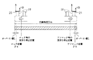
ステアリングロック7は施錠状態と解除状態の2通りの状態をとり、ステアリングシャフト18の外周面の凹部18aに係止可能なロックバー19を備えている。ロックバー19はステアリングロックモータ16を駆動源に往復動し、例えばステアリングロックモータ16が一方向に回転すると往動し、ステアリングロックモータ16が他方向に回転すると復動する。ロックバー19が往動してロック位置Pa(図2参照)に到達すると、ロックバー19が凹部18aに係止してステアリングロック7が施錠状態となる。一方、ロックバー19が復動してアンロック位置Pb(図2参照)に到達すると、凹部18a及びロックバー19の係止が解かれてステアリングロック7が解除状態となる。
The
ステアリングロック7は、ロックバー19がロック位置Paに到達したことを検出するロックスイッチ20と、ロックバー19がアンロック位置Pbに到達したことを検出するアンロックスイッチ21とを備えている。ロックスイッチ20及びアンロックスイッチ21は例えばリミットスイッチ等が用いられ、ともにステアリングロック制御部8に接続されている。ロックバー19がロック位置Paに到達すると、ロックスイッチ20がオンしてステアリングロック制御部8にオン信号を出力する。ロックバー19がアンロック位置Pbに到達すると、アンロックスイッチ21がオンしてステアリングロック制御部8にオン信号を出力する。なお、ロックスイッチ20及びアンロックスイッチ21が位置検出手段を構成する。
The
ステアリングロック制御部8は、ロックスイッチ20からオン信号を入力し、アンロックスイッチ21からオフ信号を入力すると、ステアリングロック7が施錠状態になったと認識する。一方、ステアリングロック制御部8は、ロックスイッチ20からオフ信号を入力し、アンロックスイッチ21からオン信号を入力すると、ステアリングロック7が解除状態になったと認識する。
The steering
ステアリングロック制御部8は、ステアリングロック7の作動時に実行される制御プログラムを記憶したROM22と、ロックバー19が移動を開始してからの経過時間Txを計時するカウンタ23とを備えている。制御プログラムは、ステアリングロック7を施錠すべくロックバー19をアンロック位置Pbから動かし、それをロック位置Paで止めたり、ステアリングロック7を解除すべくロックバー19をロック位置Paから動かし、それをアンロック位置Pbで止めたりするプログラムである。なお、ROM22が記憶手段に相当し、カウンタ23が計時手段に相当する。
The steering
この制御プログラムには、ロック位置Pa(アンロック位置Pb)から動き始めたロックバー19をロック位置Pa(アンロック位置Pb)で停止し得る目標時間Tkが設定されている。目標時間Tkは、移動を開始してからのロックバー19の経過時間Txがこの目標時間Tkに到達したときに、ステアリングロックモータ16に停止指令を出力すれば、モータ16が慣性等により直ぐに停止しなくても、ロックバー19がロック位置Pa(アンロック位置Pb)で停止するという時間である。言い換えるならば、目標時間Tkはロックバー19をロック位置Pa(アンロック位置Pb)で停止させるべく、ロックバー19がロック位置Pa(アンロック位置Pb)に到達する前にステアリングロックモータ16を見切り停止する際の基準となる時間である。
In this control program, a target time Tk at which the
ステアリングロック制御部8は、ステアリングロック7を施錠・解除するときロックバー作動制御を実行するが、まずロックバー19が移動を開始してからの経過時間Txをカウンタ23で計時する。ステアリングロック制御部8は経過時間Txと目標時間Tkとを逐次比較しており、経過時間Txが目標時間Tkに到達した(Tx>Tkが成立した)と判断すると、ステアリングロックモータ16に停止指令を出力する。ステアリングロックモータ16が停止指令を入力すると、慣性等による若干の回転を伴った後に停止状態となる。
The steering
ステアリングロックモータ16に駆動指令を出力した後、ステアリングロック制御部8は施錠時であればロックスイッチ20の検出信号に基づき、解除時であればアンロックスイッチ21の検出信号に基づき、ロックバー19がロック位置Pa(アンロック位置Pb)に到達したか否かを判断する。ここで、ステアリングロック7が施錠時であれば、ステアリングロック制御部8はロックスイッチ20からオン信号を入力すれば、ロックバー19がロック位置Paに到達したと認識して施錠動作が完了したと判断する。一方、ステアリングロック7が解除時であれば、ステアリングロック制御部8はアンロックスイッチ21からオン信号を入力すれば、ロックバー19がアンロック位置Pbに到達したと認識して解除動作が完了したと判断する。
After outputting the drive command to the
また、ステアリングロック制御部8は、見切り停止後もロックスイッチ20(アンロックスイッチ21)からオフ信号を入力したままの状態であれば、ロックバー19がロック位置Pa(アンロック位置Pb)に到達していないと判断して、ステアリングロックモータ16を再駆動してロックバー19を再度動かす。そして、ステアリングロック制御部8は、ロックスイッチ20(アンロックスイッチ21)からオン信号を入力した時点でステアリングロックモータ16に停止指令を出力し、ロックバー19の移動を止めて再駆動を停止する。
Further, the steering
次に、本例の電動ステアリングロック装置の作用を説明する。
駐車状態の車両1に乗り込んでエンジン9を始動するときには、室内照合成立とエンジンスイッチのエンジン始動操作とを条件に、施錠状態のステアリングロック7の解除動作が開始される。このとき、ステアリングロック制御部8がロックバー作動制御を実行し、ステアリングロック制御部8からの指令に基づきステアリングロックモータ16が一方向に回転を開始し、ロック位置Paのロックバー19がアンロック位置Pb側に移動を開始する。
Next, the operation of the electric steering lock device of this example will be described.
When entering the parked
ロックバー19がアンロック位置Pb側に移動を開始すると、ステアリングロック制御部8はロックバー19が移動を開始した時点からの経過時間Txをカウンタ23で計時する。ロックバー19がアンロック側に移動しているとき、ステアリングロック制御部8は経過時間Txと、自身のROM22に記憶した目標時間Tkとを逐次比較する。経過時間Txが目標時間Tkに到達すると、ステアリングロック制御部8はステアリングロックモータ16を見切り停止するために、ステアリングロックモータ16に停止指令を出力する。従って、図2に示すようにアンロック位置Pbの手前でステアリングロックモータ16に停止指令が出力されることになり、ステアリングロックモータ16は停止指令を受けてから若干回転して停止するので、結果としてロックバー19がアンロック位置Pb付近で停止する。
When the
ステアリングロックモータ16に停止指令を出力した後、ステアリングロック制御部8はアンロックスイッチ21からオン信号を入力したか否かを監視する。ステアリングロック制御部8は、アンロックスイッチ21からオン信号を入力するとロックバー19がアンロック位置Pbに到達したと認識して、ステアリングロック7の解除動作が完了したと判断する。
After outputting a stop command to the
一方、ステアリングロックモータ16を見切り停止してロックバー19の移動を止めたとき、アンロックスイッチ21からオン信号を入力せずにオフ信号のままであると、ステアリングロック制御部8はロックバー19がアンロック位置Pbの手前で停止したと認識して、ステアリングロックモータ16を再駆動する。これの原因としては、例えばロックバー19が凹部18aに噛み込んだ状態となっていて、直ぐにロックバー19の移動が開始されない場合等がある。そして、アンロックスイッチ21がロックバー19を検出してオン信号を出力した時点で、ステアリングロック制御部8がステアリングロックモータ16に停止指令を出力して、ロックバー19の移動を止める。
On the other hand, when the
また、エンジン9を止めて車両1から降りたときには、エンジンスイッチをオフ位置に操作したことを条件に、解除状態のステアリングロック7の施錠動作が開始される。このとき、ステアリングロック制御部8がロックバー作動制御を実行し、ステアリングロック制御部8の指令に基づきステアリングロックモータ16が他方向に回転を開始し、アンロック位置Pbのロックバー19がロック位置Pa側に移動を開始する。
When the engine 9 is stopped and the
ロックバー19がロック位置Pa側に移動を開始すると、ステアリングロック制御部8はロックバー19が移動を開始した時点からの経過時間Txをカウンタ23で計時し、この経過時間Txと目標時間Tkとを逐次比較する。経過時間Txが目標時間Tkに到達すると、ステアリングロック制御部8はステアリングロックモータ16を見切り停止するために、ステアリングロックモータ16に停止指令を出力する。従って、図2に示すようにロック位置Paの手前でステアリングロックモータ16に出力されることになり、ロックバー19は若干移動した後にロック位置Pa付近で停止する。
When the
ステアリングロックモータ16に停止指令を出力した後、ステアリングロック制御部8はロックスイッチ20からオン信号を入力したか否かを監視し、このオン信号を入力するとロックバー19がロック位置Paに到達したと認識して、ステアリングロック7の施錠動作が完了したと判断する。一方、ステアリングロックモータ16に停止指令を出力した後に、ロックスイッチ20からオン信号を入力せずにオフ信号を入力したままであると、ステアリングロック制御部8はロックバー19がロック位置Paの手前で停止したと認識して、ステアリングロックモータ16を再駆動する。そして、ロックスイッチ20からオン信号を入力した時点で、ステアリングロック制御部8がステアリングロックモータ16に停止指令を出力して、ロックバー19の移動を止める。
After outputting a stop command to the
このように本例では、ロックバー19が移動を開始した後の経過時間Txが目標時間Tkに到達したときにステアリングロックモータ16を停止する、つまりステアリングロックモータ16を見切り停止する。従って、ロックバー19がロック位置Pa又はアンロック位置Pb付近で停止することになり、ロックバー19のオーバーラン量L(図2参照)が少なく済む。よって、ステアリングロック7の作動時間Tmが短く済み、作動時間Tmの低減に伴って作動音発生時間も短く済み、ステアリングロック7の施解除後に行う次の制御への応答性も高まる。
Thus, in this example, when the elapsed time Tx after the
本実施形態の構成によれば、以下に記載の効果を得ることができる。
(1)ロックバー19が移動を開始した後の経過時間Txが目標時間Tkに到達したときにステアリングロックモータ16を停止する、つまりステアリングロックモータ16を見切り停止する。従って、ロックバー19がロック位置Pa又はアンロック位置Pb付近で停止することになり、ロックバー19のオーバーラン量Lを少なく抑えることができる。よって、ステアリングロック7の作動時間Tmの短縮化、作動音発生時間の短縮化、ステアリングロック7の応答性向上を図ることができる。
According to the configuration of the present embodiment, the following effects can be obtained.
(1) When the elapsed time Tx after the
(2)ステアリングロックモータ16を見切り停止したとき、ロックバー19がロック位置Pa(アンロック位置Pb)に到達していなければ、ステアリングロックモータ16を再駆動して、ロックバー19をロック位置Pa(アンロック位置Pb)まで移動させる。従って、見切り停止時にロックバー19がロック位置Pa(アンロック位置Pb)の手前で停止しても、ロックバー19をロック位置Pa(アンロック位置Pb)まで移動させることができ、ステアリングロック7を施錠状態又は解除状態にすることができる。
(2) When the
(3)ステアリングロックモータ16を再駆動した際には、ロックスイッチ20又はアンロックスイッチ21からオン状態となったことを条件にステアリングロックモータ16を止める構成をとるので、再駆動させたステアリングロックモータ16を簡単な制御で停止することができる。
(3) When the
(4)ステアリングロック7を施錠状態するときと解除状態にするときとの両方で、ステアリングロックモータ16の見切り停止を行うので、ステアリングロック7を施錠するときと解錠するときとの両方でロックバー19のオーバーラン量Lを少なく抑えることができる。従って作動音発生時間の低減化、ステアリングロック動作後の次の制御へ移る際の応答性向上に一層寄与する。
(4) Since the
(5)ステアリングロック7を施錠状態にするときと解除状態にするときとの両方で同じ値の目標時間Tkを用いるので、ロックバー19のオーバーラン量Lを少なく抑える制御の簡素化を図ることができる。
(5) Since the target time Tk having the same value is used both when the
なお、本実施形態は前記構成に限定されず、以下の態様に変更してもよい。
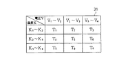
・ 目標時間Tkは一定値をとることに限らず、例えばステアリングロックモータ16に印加される電圧Vと、ステアリングロックモータ16の温度Kとの値に基づき目標時間Tkが決まるように、ステアリングロックモータ16の負荷状況に応じて可変としてもよい。この方法としては、例えば電圧V及び温度Kをパラメータとした図3に示すテーブル31をROM22に用意しておき、温度がK1〜K2の条件下で電圧がV1〜V2のときにはT1に、V2〜V3のときにはT2に、V3〜V4のときにはT3と設定する方法がある。この場合、好適な目標時間Tkを使用することが可能となり、オーバーラン量低減化に一層寄与する。
In addition, this embodiment is not limited to the said structure, You may change into the following aspects.
The target time Tk is not limited to a constant value. For example, the steering lock motor is determined so that the target time Tk is determined based on the value of the voltage V applied to the
・ 目標時間Tkは、ステアリングロック7の施錠時と解除時との両方で同じ値をとることに限らず、これを異なる値にしてもよい。
・ ステアリングロックモータ16を再駆動するとき、ロックバー19の移動速度を再駆動前の通常駆動時より低速で行ってもよい。
The target time Tk is not limited to take the same value both when the
-When the
・ ステアリングロックモータ16の再駆動時にロックバー19をロック位置Pa又はアンロック位置Pbで止める方法は、ロックスイッチ20又はアンロックスイッチ21の検出信号に基づき行われることに限定されない。例えば、見切り停止後のロックバー19をロック位置Pa(アンロック位置Pb)で止め得る第2目標時間TsをROM22(第2記憶手段)に記憶しておく。そして、ステアリングロックモータ16を再駆動した後、その経過時間Txが第2目標時間Tsに到達するとステアリングロックモータ16に停止指令を出力して、ロックバー19の移動を止める。ここで、ロックバー19がロック位置Pa(アンロック位置Pb)に到達していなければ、ステアリングロックモータ16を再々駆動し、ロックバー19がロック位置Pa(アンロック位置Pb)に到達するまでこの処理を繰り返す。この場合も、ロックバー19のオーバーラン量低減化が図られる。
The method of stopping the
また、ステアリングロックモータ16の再駆動時にロックバー19をロック位置Pa又はアンロック位置Pbで止める方法は、以下の方法を用いてもよい。値が段階的(例えば、50ms、40ms、30ms、…)となるように第2目標時間Tsが複数記憶され、再駆動の際、まず最初に最も値の大きい第2目標時間Tsを用いてステアリングロックモータ16の再駆動を行う。そして、再駆動してもロックバー19がロック位置Pa(アンロック位置Pb)に到達していなければ、次に値の大きい第2目標時間Tsを用いてステアリングロックモータ16を再々駆動し、ロックバー19がロック位置Pa(アンロック位置Pb)に到達するまでこの処理を繰り返す。この場合も、ロックバー19のオーバーラン量低減化が図られる。
Further, as a method of stopping the
・ ロックバー作動制御は、ステアリングロック7の施錠時と解除時の両方で行われることに限らず、どちらか一方のときのみに実施されてもよい。
・ ロックバー作動制御で経過時間Txが目標時間Tkに到達したにも拘らず、ロックバー19がロック位置Pa(アンロック位置Pb)に到達していないとき、ステアリングロックモータ16を再駆動することに限定されない。例えば、再駆動することに代えてブザー等により運転者にその旨を通知するようにしてもよい。
The lock bar operation control is not limited to being performed both when the
The
・ 位置検出手段は、リミットスイッチ式のロックスイッチ20やアンロックスイッチ21に限らず、例えば光センサや磁気センサ等を用いてもよい。
・ 電子キー3は、ID照合が成立すればドアが施解錠されるキーに限らず、ID照合が許可された時点でドアの施解錠が許可された状態となり、この状態でドアノブのロックボタンを押すとドアロックが施錠状態となり、ドアノブに手を触れるとドアロックが解除状態となるものでもよい。また、電子キー3は、例えば電子キー3のロックボタンを押すとドアが施錠され、アンロックボタンを押すとドアが解錠される電波キーでもよい。
The position detection means is not limited to the limit switch
The
7…ステアリングロック、8…制御手段、再駆動手段及び設定手段を構成するステアリングロック制御部、16…アクチュエータとしてのステアリングロックモータ、19…ロックバー、20…位置検出手段を構成するロックスイッチ、21…位置検出手段を構成するアンロックスイッチ、22…記憶手段としてのROM、23…計時手段としてのカウンタ、Pa…目標停止位置としてのロック位置、Pb…目標停止位置としてのアンロック位置、Tx…経過時間、Tk…目標時間。 7 ... Steering lock, 8 ... Steering lock control unit constituting control means, re-driving means and setting means, 16 ... Steering lock motor as actuator, 19 ... Lock bar, 20 ... Lock switch constituting position detection means, 21 ... Unlock switch constituting position detection means, 22... ROM as storage means, 23... Counter as timekeeping means, Pa... Lock position as target stop position, Pb... Unlock position as target stop position, Tx. Elapsed time, Tk ... target time.
Claims (5)
アンロック位置又はロック位置から動き始めた前記ロックバーを目標停止位置で止めるべく、該ロックバーが前記目標停止位置に到達する前にアクチュエータを見切り停止させる際の基準の時間として目標時間を記憶した記憶手段と、
前記ステアリングロックが施錠状態及び解除状態の少なくとも一方となる際に、前記ロックバーが移動を開始してからの経過時間を計時する計時手段と、
前記経過時間と前記目標時間とを比較し、前記経過時間が前記目標時間に到達したときに前記アクチュエータに停止指令を出力して、前記ロックバーを見切り停止させる制御手段と
を備えたことを特徴とする電動ステアリングロック装置。 In the electric steering lock device in which the lock bar is moved forward by the actuator so that the steering lock is locked, and the lock bar is moved backward by the actuator so that the steering lock is released.
Stopping the locking bar starts moving from the unlocked position or the lock position at the target stop position Rubeku, stores a target time as a reference time for the actuator to closeout stopped before the lock bar reaches the target stop position Storage means
When the steering lock is at least one of a locked state and a released state, time measuring means for measuring an elapsed time after the lock bar starts moving,
Characterized in that by comparing the target time and the elapsed time, the elapsed time by outputting a stop command to the actuator upon reaching the target time, and a control means for parting stop the locking bar Electric steering lock device.
前記制御手段が前記アクチュエータに停止指令を出力して前記ロックバーの移動を停止させた際に、前記位置検出手段の検出信号に基づき前記ロックバーの停止位置が前記目標停止位置に到達していないと判断したとき、前記アクチュエータを再駆動する再駆動手段とを備え、
前記再駆動手段は、前記アクチュエータを再駆動するとき、再駆動を行う前の通常時における前記ロックバーの移動速度よりも低い速度で前記ロックバーを移動させることを特徴とする請求項1又は2に記載の電動ステアリングロック装置。 Position detecting means for detecting that the lock bar has reached the target stop position ;
When the control means outputs a stop command to the actuator to stop the movement of the lock bar, the stop position of the lock bar has not reached the target stop position based on the detection signal of the position detection means And re-driving means for re-driving the actuator,
The re-driving means moves the lock bar at a speed lower than a moving speed of the lock bar at a normal time before re-driving when the actuator is re-driven. The electric steering lock device described in 1.
前記再駆動手段は、前記アクチュエータの再駆動時、再駆動時の経過時間と前記第2目標時間とを比較し、再駆動時の経過時間が前記第2目標時間に到達すると前記アクチュエータに停止指令を出力して前記ロックバーの移動を停止させ、前記ロックバーが前記目標停止位置に到達していないと判断すれば前記アクチュエータを再々駆動し、これら処理を前記ロックバーが前記目標停止位置に到達するまで繰り返し行うことを特徴とする請求項3に記載の電動ステアリングロック装置。 A second storage means for storing a second target time required until the lock bar that has started to move at the target stop position when the actuator is re-driven;
The re-driving means compares the elapsed time at the time of re-driving and the second target time when the actuator is re-driven, and instructs the actuator to stop when the elapsed time at the time of re-driving reaches the second target time. Is output to stop the movement of the lock bar, and if it is determined that the lock bar has not reached the target stop position, the actuator is driven again, and these processes are performed by the lock bar reaching the target stop position. The electric steering lock device according to claim 3 , wherein the electric steering lock device is repeatedly performed until it is performed.
Priority Applications (1)
| Application Number | Priority Date | Filing Date | Title |
|---|---|---|---|
| JP2004172625A JP4279727B2 (en) | 2004-06-10 | 2004-06-10 | Electric steering lock device |
Applications Claiming Priority (1)
| Application Number | Priority Date | Filing Date | Title |
|---|---|---|---|
| JP2004172625A JP4279727B2 (en) | 2004-06-10 | 2004-06-10 | Electric steering lock device |
Publications (2)
| Publication Number | Publication Date |
|---|---|
| JP2005349947A JP2005349947A (en) | 2005-12-22 |
| JP4279727B2 true JP4279727B2 (en) | 2009-06-17 |
Family
ID=35584770
Family Applications (1)
| Application Number | Title | Priority Date | Filing Date |
|---|---|---|---|
| JP2004172625A Expired - Fee Related JP4279727B2 (en) | 2004-06-10 | 2004-06-10 | Electric steering lock device |
Country Status (1)
| Country | Link |
|---|---|
| JP (1) | JP4279727B2 (en) |
Families Citing this family (3)
| Publication number | Priority date | Publication date | Assignee | Title |
|---|---|---|---|---|
| DE102008013487A1 (en) * | 2008-03-10 | 2009-09-17 | Huf Hülsbeck & Fürst Gmbh & Co. Kg | Method and device for controlling a locking member |
| JP5170113B2 (en) | 2009-07-24 | 2013-03-27 | 株式会社デンソー | Vehicle door control system, vehicle door control device, and vehicle door control device program |
| JP2015093654A (en) * | 2013-11-14 | 2015-05-18 | 株式会社東海理化電機製作所 | Lock device, and electric steering lock device |
-
2004
- 2004-06-10 JP JP2004172625A patent/JP4279727B2/en not_active Expired - Fee Related
Also Published As
| Publication number | Publication date |
|---|---|
| JP2005349947A (en) | 2005-12-22 |
Similar Documents
| Publication | Publication Date | Title |
|---|---|---|
| US8054158B2 (en) | On-vehicle equipment control system | |
| US7254466B2 (en) | Engine start controller | |
| KR100792217B1 (en) | Remote start control | |
| US11267439B2 (en) | Activation of valet mode for vehicles | |
| US20050099263A1 (en) | Keyless entry system | |
| US20110068895A1 (en) | Control of a Vehicle Having a Passive Entry-Passive Start Function | |
| US7199710B2 (en) | Controller for remote control system | |
| JP5482700B2 (en) | Vehicle door opening / closing control device | |
| JP2012066689A (en) | Vehicle control system, vehicle control method, and engine control device | |
| US20060076834A1 (en) | Engine start control system for vehicle | |
| JP5599759B2 (en) | Start control device | |
| JP4279727B2 (en) | Electric steering lock device | |
| JP2003214004A (en) | Door lock control method and door lock device | |
| JP4279728B2 (en) | Electric steering lock device | |
| JP3918523B2 (en) | Unique code registration method in vehicle remote control system | |
| WO2014125650A1 (en) | Vehicle control device | |
| JP3525580B2 (en) | Keyless entry device | |
| JP3857383B2 (en) | Steering lock system for vehicles | |
| JP4364764B2 (en) | Electric steering lock device | |
| KR100817659B1 (en) | Vehicle engine control system and method | |
| EP1339026B1 (en) | Electronic key apparatus for vehicle and arrest cancellation method for rotation arresting device | |
| JP5083412B2 (en) | Vehicle control apparatus and method | |
| JP2010138815A (en) | Control device and control method | |
| JP6629680B2 (en) | Vehicle control system, vehicle control device, portable device | |
| JPH04244456A (en) | Keyless entry device for vehicle |
Legal Events
| Date | Code | Title | Description |
|---|---|---|---|
| A621 | Written request for application examination |
Free format text: JAPANESE INTERMEDIATE CODE: A621 Effective date: 20061020 |
|
| A977 | Report on retrieval |
Free format text: JAPANESE INTERMEDIATE CODE: A971007 Effective date: 20081127 |
|
| A131 | Notification of reasons for refusal |
Free format text: JAPANESE INTERMEDIATE CODE: A131 Effective date: 20081202 |
|
| A521 | Written amendment |
Free format text: JAPANESE INTERMEDIATE CODE: A523 Effective date: 20090105 |
|
| A131 | Notification of reasons for refusal |
Free format text: JAPANESE INTERMEDIATE CODE: A131 Effective date: 20090127 |
|
| A521 | Written amendment |
Free format text: JAPANESE INTERMEDIATE CODE: A523 Effective date: 20090206 |
|
| TRDD | Decision of grant or rejection written | ||
| A01 | Written decision to grant a patent or to grant a registration (utility model) |
Free format text: JAPANESE INTERMEDIATE CODE: A01 Effective date: 20090303 |
|
| A01 | Written decision to grant a patent or to grant a registration (utility model) |
Free format text: JAPANESE INTERMEDIATE CODE: A01 |
|
| A61 | First payment of annual fees (during grant procedure) |
Free format text: JAPANESE INTERMEDIATE CODE: A61 Effective date: 20090312 |
|
| FPAY | Renewal fee payment (prs date is renewal date of database) |
Free format text: PAYMENT UNTIL: 20120319 Year of fee payment: 3 |
|
| R150 | Certificate of patent (=grant) or registration of utility model |
Free format text: JAPANESE INTERMEDIATE CODE: R150 |
|
| FPAY | Renewal fee payment (prs date is renewal date of database) |
Free format text: PAYMENT UNTIL: 20130319 Year of fee payment: 4 |
|
| FPAY | Renewal fee payment (prs date is renewal date of database) |
Free format text: PAYMENT UNTIL: 20140319 Year of fee payment: 5 |
|
| LAPS | Cancellation because of no payment of annual fees |