JP4300529B2 - Vane pump - Google Patents
Vane pump Download PDFInfo
- Publication number
- JP4300529B2 JP4300529B2 JP2004321909A JP2004321909A JP4300529B2 JP 4300529 B2 JP4300529 B2 JP 4300529B2 JP 2004321909 A JP2004321909 A JP 2004321909A JP 2004321909 A JP2004321909 A JP 2004321909A JP 4300529 B2 JP4300529 B2 JP 4300529B2
- Authority
- JP
- Japan
- Prior art keywords
- rotor
- shaft
- center
- gravity
- vane
- Prior art date
- Legal status (The legal status is an assumption and is not a legal conclusion. Google has not performed a legal analysis and makes no representation as to the accuracy of the status listed.)
- Expired - Fee Related
Links
Images



Classifications
-
- F—MECHANICAL ENGINEERING; LIGHTING; HEATING; WEAPONS; BLASTING
- F04—POSITIVE - DISPLACEMENT MACHINES FOR LIQUIDS; PUMPS FOR LIQUIDS OR ELASTIC FLUIDS
- F04C—ROTARY-PISTON, OR OSCILLATING-PISTON, POSITIVE-DISPLACEMENT MACHINES FOR LIQUIDS; ROTARY-PISTON, OR OSCILLATING-PISTON, POSITIVE-DISPLACEMENT PUMPS
- F04C15/00—Component parts, details or accessories of machines, pumps or pumping installations, not provided for in groups F04C2/00 - F04C14/00
- F04C15/0057—Driving elements, brakes, couplings, transmission specially adapted for machines or pumps
- F04C15/0061—Means for transmitting movement from the prime mover to driven parts of the pump, e.g. clutches, couplings, transmissions
- F04C15/0073—Couplings between rotors and input or output shafts acting by interengaging or mating parts, i.e. positive coupling of rotor and shaft
-
- F—MECHANICAL ENGINEERING; LIGHTING; HEATING; WEAPONS; BLASTING
- F04—POSITIVE - DISPLACEMENT MACHINES FOR LIQUIDS; PUMPS FOR LIQUIDS OR ELASTIC FLUIDS
- F04C—ROTARY-PISTON, OR OSCILLATING-PISTON, POSITIVE-DISPLACEMENT MACHINES FOR LIQUIDS; ROTARY-PISTON, OR OSCILLATING-PISTON, POSITIVE-DISPLACEMENT PUMPS
- F04C2230/00—Manufacture
- F04C2230/60—Assembly methods
Landscapes
- Engineering & Computer Science (AREA)
- Mechanical Engineering (AREA)
- General Engineering & Computer Science (AREA)
- Rotary Pumps (AREA)
Description
本発明は、ロータとともに回転するベーンによりポンプ室の流体を加圧または減圧するベーン式ポンプに関する。 The present invention relates to a vane pump that pressurizes or depressurizes fluid in a pump chamber by a vane that rotates together with a rotor.
ハウジングと偏心配置したロータを回転させ、ハウジングとロータとの間に形成されたポンプ室の流体をロータとともに回転するベーンにより加圧するベーン式ポンプが公知である。ベーン式ポンプのロータは、例えば電気モータなどにより回転駆動される。モータのシャフトとロータとは主に圧入により接続されている(例えば、特許文献1参照)。 A vane pump is known in which a rotor arranged eccentrically with a housing is rotated, and a fluid in a pump chamber formed between the housing and the rotor is pressurized by a vane that rotates together with the rotor. The rotor of the vane pump is rotationally driven by, for example, an electric motor. The motor shaft and the rotor are connected mainly by press-fitting (see, for example, Patent Document 1).
ロータは、ハウジングの内部を高速で回転する。そのため、ロータおよびハウジングの寸法誤差が大きくなったり、ロータに圧入されるシャフトに傾きが生じると、ロータとハウジングとが接触するおそれがある。ロータとハウジングとが接触すると、ロータがロックしたり、異音の発生を招いたり、ロータおよびハウジングの摩耗を招く。また、ロータとハウジングとの接触を低減するためにロータとハウジングとの間に隙間を確保すると、加圧された流体の漏れが大きくなり、ポンプ効率が低下する。さらに、シャフトとロータとを圧入する場合、シャフトの圧入によってロータの変形を招く。これらの理由から、ロータ、ハウジングおよびシャフトの寸法の管理に要求される精度は高くなり、組み付けの精度が高くなるため、部品あるいは組み付けコストが高くなる。 The rotor rotates inside the housing at high speed. Therefore, if the dimensional error of the rotor and the housing becomes large or the shaft that is press-fitted into the rotor is inclined, the rotor and the housing may come into contact with each other. When the rotor and the housing come into contact with each other, the rotor is locked, abnormal noise is generated, or the rotor and the housing are worn. In addition, if a clearance is secured between the rotor and the housing in order to reduce contact between the rotor and the housing, leakage of pressurized fluid increases and pump efficiency decreases. Further, when the shaft and the rotor are press-fitted, the deformation of the rotor is caused by the press-fitting of the shaft. For these reasons, the precision required for managing the dimensions of the rotor, the housing and the shaft is increased, and the precision of the assembly is increased, so that the parts or the assembly cost is increased.
そこで、寸法の公差をロータとシャフトとの間で吸収するために、例えば隙間を許容してロータとシャフトを組み付けることが考えられる。しかしながら、ロータとシャフトとの間に隙間を許容すると、ロータは回転時に許容された隙間の範囲でぶれを生じる。そのため、作動音の増大を招いたり、ポンプから吐出される流体の圧力が変動するという問題がある。 Therefore, in order to absorb the dimensional tolerance between the rotor and the shaft, for example, it is considered that the rotor and the shaft are assembled while allowing a gap. However, if a clearance is allowed between the rotor and the shaft, the rotor is shaken within the range of the clearance allowed during rotation. For this reason, there is a problem that the operation noise increases and the pressure of the fluid discharged from the pump fluctuates.
そこで、本発明の目的は、組み付けが容易であり、作動音および圧力変動が小さなベーン式ポンプを提供することにある。 SUMMARY OF THE INVENTION An object of the present invention is to provide a vane pump that is easy to assemble and has low operating noise and pressure fluctuation.
請求項1記載の発明では、ロータは回転の中心軸と重心とがずれている。これにより、ロータが回転すると、ロータには遠心力によって重心方向へ力が生じる。すなわち、ロータには、回転によって常に一定方向へ押し付ける力が生じる。そのため、ロータは、回転によってシャフトに押し付けられる。その結果、ロータとシャフトとの間に隙間が許容される場合でも、ロータの回転時、ロータとシャフトとは密着する。したがって、ロータは安定して回転し、作動音および圧力変動を低減することができる。また、ロータとシャフトとの間に隙間が許容されるので、組み付けを容易にすることができる。 According to the first aspect of the present invention, the center axis of rotation of the rotor is shifted from the center of gravity. Thus, when the rotor rotates, a force is generated in the direction of the center of gravity by centrifugal force. That is, a force that always presses the rotor in a certain direction by rotation is generated. Therefore, the rotor is pressed against the shaft by rotation. As a result, even when a gap is allowed between the rotor and the shaft, the rotor and the shaft are in close contact with each other when the rotor is rotated. Therefore, the rotor can rotate stably, and operation noise and pressure fluctuation can be reduced. Moreover, since a clearance is allowed between the rotor and the shaft, assembly can be facilitated.
請求項2記載の発明では、ロータは一部を除去することにより重心が移動する。これにより、ロータの除去する部分を調整することにより、中心軸と重心とのずれを任意に調整することができる。
請求項3記載の発明では、ロータは凹部を有している。凹部は、ロータの軸方向の一方の端部側から他方の端部側へ窪んでいる。凹部を形成することにより、ロータの重量は軽くなり、ロータの重心は移動する。また、凹部の数、位置、径または深さなどを調整することにより、軽減する重量は任意に調整される。したがって、簡単な構造で中心軸と重心とのずれを任意に調整することができる。
In the invention according to claim 2, the center of gravity moves by removing a part of the rotor. Thereby, by adjusting the part which a rotor removes, the shift | offset | difference of a central axis and a gravity center can be adjusted arbitrarily.
In the invention described in claim 3, the rotor has a recess. The recess is recessed from one end side in the axial direction of the rotor to the other end side. By forming the recess, the weight of the rotor is reduced and the center of gravity of the rotor moves. Further, the weight to be reduced can be arbitrarily adjusted by adjusting the number, position, diameter, depth, or the like of the recesses. Therefore, the deviation between the center axis and the center of gravity can be arbitrarily adjusted with a simple structure.
請求項4記載の発明では、ロータは切欠部を有している。切欠部は、ロータの周方向の一部が内周側へ切り欠かれている。切欠部を形成することにより、ロータの重量は軽くなり、ロータの重心は移動する。また、切欠部の数、大きさまたは位置などを調整することにより、軽減する重量は任意に調整される。したがって、簡単な構造で中心軸と重心とのずれを任意に調整することができる。 In the invention described in claim 4, the rotor has a notch. As for the notch part, a part of the circumferential direction of the rotor is notched to the inner periphery side. By forming the notch, the weight of the rotor is reduced and the center of gravity of the rotor moves. Further, the weight to be reduced can be arbitrarily adjusted by adjusting the number, size, or position of the cutouts. Therefore, the deviation between the center axis and the center of gravity can be arbitrarily adjusted with a simple structure.
請求項5記載の発明では、ロータは一部に錘を設置することにより重心が移動する。これにより、錘の数、重量または位置などを調整することにより、中心軸と重心とのずれを任意に調整することができる。
請求項6記載の発明では、錘はロータの凹部に設置されている。これにより、錘は凹部の内部に収容され、ロータの端面から突出しない。そのため、ロータに設置された錘がケーシングに接触することはない。したがって、錘とケーシングとの接触による異音の発生および局部的な摩耗などを防止することができる。
In the invention according to claim 5, the center of gravity of the rotor is moved by installing a weight in part. Thereby, the shift | offset | difference of a center axis | shaft and a gravity center can be adjusted arbitrarily by adjusting the number, weight, or position of a weight.
In the invention according to claim 6, the weight is installed in the concave portion of the rotor. As a result, the weight is accommodated in the recess and does not protrude from the end face of the rotor. Therefore, the weight installed on the rotor does not contact the casing. Therefore, it is possible to prevent abnormal noise due to contact between the weight and the casing and local wear.
以下、本発明の複数の実施形態を図面に基づいて説明する。
(第1実施形態)
本発明の第1実施形態によるベーン式ポンプを図1および図2に示す。ベーン式ポンプ10は、流体を加圧または減圧して吐出する。ベーン式ポンプ10で加圧される流体としては、例えば空気などの気体や水などの液体を適用することができる。本実施形態では、ベーン式ポンプ10は流体を加圧する例について説明する。
Hereinafter, a plurality of embodiments of the present invention will be described with reference to the drawings.
(First embodiment)
A vane pump according to a first embodiment of the present invention is shown in FIGS. The
ベーン式ポンプ10は、リング20、プレート31、プレート32、ロータ40およびベーン41を備えている。ベーン式ポンプ10は、プレート31を挟んで設置されている駆動部としてのモータ11により駆動される。モータ11には、例えば直流式または交流式の電気モータが適用される。モータ11は、図示しない固定子が収容されているカバー12と、図示しない可動子とともに回転するシャフト13とを有している。
The
リング20は、略円筒形状に形成されており、内周側にロータ40を収容している。リング20の内周壁21は、略円筒面状である。リング20は、軸方向の両端部がプレート31およびプレート32により覆われている。プレート31は、リング20のモータ11側の端部を覆っている。リング20、プレート31およびプレート32は、特許請求の範囲のケーシングを構成している。なお、リング20の内周壁21は、円筒形状の面に限らず、楕円筒形状の面であってもよい。
The
ロータ40は、リング20の内周側に収容されている。これにより、リング20と、プレート31と、プレート32と、ロータ40とから囲まれた空間にポンプ室22が形成される。ロータ40は、リング20の内周壁21と偏心して設置されている。そのため、リング20とロータ40との間に形成されるポンプ室22は、周方向へ容積が変化している。ポンプ室22には、流体入口通路23および流体出口通路24が連通している。流体入口通路23は、プレート31の孔部33を経由してベーン式ポンプ10の外側に連通している。流体出口通路24は、ポンプ室22から径方向外側へ伸びて形成されている。流体出口通路24は、リング20の溝部25とプレート31との間に形成されている。
The
ロータ40は、略円筒状に形成され、中心部に中心孔42を有している。モータ11のシャフト13は、ロータ40の中心孔42に挿入される。中心孔42は、プレート31側の端部から軸方向の途中まで円形状の断面に形成されている。また、中心孔42は、軸方向の途中からプレート32側の端部まで断面が半円形状に形成されている。これにより、中心孔42は軸方向の途中に段差43を有している。モータ11のシャフト13は、中心孔42と同様に、カバー12側の端部から軸方向の途中まで断面が円形状に形成され、軸方向の途中からカバー12とは反対側の端部まで断面が半円形状に形成されている。これにより、シャフト13は、軸方向の途中に段差14を有している。
The
中心孔42およびシャフト13は、断面の形状が概ね同一であり、いずれも段差43または段差14を有している。また、シャフト13の外径は、中心孔42の内径よりやや小さい。これにより、中心孔42にシャフト13を挿入すると、ロータ40とシャフト13とは緩く噛み合った状態で嵌合する。これにより、シャフト13が回転すると、ロータ40はシャフト13とともに回転する。
The
ロータ40は、外周面から径方向内側へ窪んで伸びる溝部44を有している。本実施形態の場合、溝部44はロータ40の周方向へ等間隔に四つ形成されている。ロータ40の溝部44には、ベーン41が径方向へ往復移動可能に収容される。ロータ40とリング20の内周壁21とは偏心しているので、ロータ40の回転にともなってロータ40とリング20の内周壁21との間の距離は変化する。ロータ40が回転すると、遠心力によりベーン41は径方向外側へ内周壁21と接するまで突出する。そして、ロータ40とリング20の内周壁21との距離が小さくなるにしたがって、ベーン41は溝部44の径方向内側へ収容される。これにより、ベーン41は、ロータ40の回転にともなって径方向外側の端部がリング20の内周壁21と接触しながら回転する。なお、ベーン41および溝部44の数は、四つに限らず、一つ以上であれば任意に選択することができる。
The
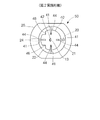
また、ロータ40は凹部45を有している。凹部45は、ロータ40のプレート32側の端部からプレート31側の端部へ窪んで形成されている。すなわち、凹部45は、ロータ40の軸方向の一方の端部から他方の端部側へ窪んで形成されている。本実施形態の場合、ロータ40は二か所の凹部45を有している。凹部45を形成することにより、図3に示す対称軸pを中心に、ロータ40は両側の形状が異なる。これにより、ロータ40は、対称軸pを中心に両側の質量が異なる。すなわち、ロータ40は、凹部45をくり抜いて除去することにより、凹部45に対応する質量が減少する。その結果、ロータ40は、対称軸pを中心としたとき、図3の左方の質量が小さくなる。なお、ベーン式ポンプ10の構造の理解を容易にするため、図1と図2とでは凹部45の位置が整合していない。
The
凹部45に対応する部分においてロータ40の質量が減少すると、ロータ40の重心cはロータ40の中心よりも凹部45が形成されていない側へ移動する。一方、ロータ40はモータ11のシャフト13とともに回転する。そのため、ロータ40の回転中心はシャフト13の中心軸qと一致する。その結果、ロータ40は、重心cと回転の中心軸qとがずれる。図3に示す場合、凹部45を形成することにより、ロータ40の重心cは回転の中心軸qよりも右方へ移動する。
When the mass of the
ロータ40に凹部45を形成すると、上述のようにロータ40は回転の中心軸qと重心cとがずれる。これにより、ロータ40を回転させたとき、ロータ40の凹部45を有する側に加わる遠心力をf1とし、ロータ40の凹部45を有しない側に加わる遠心力をf2とすると、f1<f2となる。そのため、ロータ40は、凹部45を有しない側、すなわち重心c側へ引っ張られる。その結果、ロータ40が回転すると、ロータ40はシャフト13へ押し付けられる。これにより、ロータ40の回転時、ロータ40は加わる遠心力の差によりシャフト13と密着し、ロータ40とシャフト13との間のがたつきは低減される。
When the
また、本実施形態では、凹部45は半円形の断面を有するシャフト13および中心孔42の円弧面側に配置されている。そのため、ロータ40の回転にともなって遠心力に差が生じると、ロータ40の中心孔42とシャフト13とは円弧面同士で接触する。中心孔42とシャフト13とが円弧面同士で接触することにより、平面同士が接触する場合と比較して、シャフト13とロータ40との間のがたつきは低減する。その結果、シャフト13およびロータ40の中心孔42に高い寸法精度が要求されず、シャフト13およびロータ40の加工は容易になる。
In the present embodiment, the
次に、上記の構成のベーン式ポンプ10の作動について説明する。
モータ11の回転にともなってシャフト13に接続しているロータ40は回転する。ロータ40の回転にともなって、ベーン41はリング20の内周壁21と接触しながらロータ40とともに回転する。ポンプ室22の容積は回転方向に変化している。ポンプ室22の容積は、流体入口通路23側ほど大きく、流体出口通路24側ほど小さい。そのため、ベーン41がロータ40とともに回転することにより、ポンプ室22の流体は流体入口通路23側から流体出口通路24側へかけて加圧されながらポンプ室22を流れる。これにより、流体入口通路23から吸入された流体は、ロータ40とともに回転するベーン41によってポンプ室22の内部で加圧され、流体出口通路24からベーン式ポンプ10の外部へ吐出される。ロータ40の回転により、流体は連続して加圧される。
Next, the operation of the
As the
以上、説明した第1実施形態では、ロータ40に凹部45を設置することにより、ロータ40の回転の中心軸qと重心cとの間にずれが生じる。そのため、ロータ40に加わる遠心力が不均衡となり、ロータ40にはシャフト13側へ押し付ける力が加わる。これにより、段差14を有するシャフト13と段差43を有する中心孔42との緩い噛み合いによってシャフト13とロータ40とを組み付ける場合でも、ロータ40はシャフト13とともに安定して回転する。したがって、ロータ40の回転時におけるシャフト13とロータ40とのがたつきが低減され、作動音および吐出される流体の圧力変動を低減することができる。
As described above, in the first embodiment described above, by providing the
また、第1実施形態では、シャフト13とロータ40とは緩い噛み合いによって組み付けられる。そのため、シャフト13とロータ40との間には隙間の形成が許容される。これにより、シャフト13はロータ40に圧入されない。その結果、シャフト13および中心孔42の中心軸に対する傾き、シャフト13およびロータ40の形状精度などを高めることなく、ロータ40の安定した回転が確保される。したがって、シャフト13およびロータ40の形状精度の確保にともなう加工工数およびコストの増大を抑制することができる。
In the first embodiment, the
さらに、第1実施形態では、ロータ40の回転の中心軸qと重心cとは凹部45を形成することによりずれを生じさせている。そのため、凹部45の数、位置、径または深さなどを調整することにより、ロータ40の重心cは任意の位置に調整される。したがって、ロータ40の材質、回転数および形状によって、ロータ40の重心を容易に調整することができる。
Furthermore, in the first embodiment, the center axis q and the center of gravity c of the rotation of the
(第2実施形態)
本発明の第2実施形態によるベーン式ポンプを図4に示す。なお、第1実施形態と実質的に同一の構成部位には同一の符号を付し、説明を省略する。
図4に示す第2実施形態によるベーン式ポンプ50は、ロータ40に切欠部46を有している。切欠部46は、ロータ40の周方向の一部を除去することにより形成されている。切欠部46は、ロータ40の外周面から径方向内側へ窪んで形成されている。ロータ40に切欠部46を形成することにより、切欠部46に対応する部位の質量は軽減する。そのため、ロータ40の重心は、回転の中心軸からずれる。
(Second Embodiment)
A vane pump according to a second embodiment of the present invention is shown in FIG. In addition, the same code | symbol is attached | subjected to the component substantially the same as 1st Embodiment, and description is abbreviate | omitted.
A
第2実施形態では、ロータ40の一部を切欠部46によって除去することにより重心を回転の中心軸からずらしている。これにより、ロータ40に加わる遠心力に差が生じ、ロータ40はシャフト13に押し付けられる。そのため、ロータ40はシャフト13とともに安定して回転する。したがって、ロータ40の回転時におけるシャフト13とロータ40とのがたつきが低減され、作動音および吐出される流体の圧力変動を低減することができる。
In the second embodiment, the center of gravity is shifted from the central axis of rotation by removing a part of the
(第3実施形態)
本発明の第3実施形態によるベーン式ポンプを図5に示す。なお、第1実施形態と実質的に同一の構成部位には同一の符号を付し、説明を省略する。
図5に示す第3実施形態によるベーン式ポンプ60は、ロータ40に錘61を有している。錘61は、ロータ40の凹部62に設置されている。凹部62は、第1実施形態と同様にプレート32側の端部からプレート31側へ端部へ窪んで形成されている。錘61は、この凹部62の内部に収容されている。ロータ40に錘61を設置することにより、錘61に対応する部位の質量は増加する。そのため、ロータ40の重心は、回転の中心軸からずれる。
(Third embodiment)
A vane pump according to a third embodiment of the present invention is shown in FIG. In addition, the same code | symbol is attached | subjected to the component substantially the same as 1st Embodiment, and description is abbreviate | omitted.
A
第3実施形態では、ロータ40に錘61を設置することにより重心を回転の中心からずらしている。これにより、ロータ40に加わる遠心力に差が生じ、ロータ40はシャフト13に押し付けられる。そのため、ロータ40はシャフト13とともに安定して回転する。したがって、ロータ40の回転時におけるシャフト13とロータ40とのがたつきが低減され、作動音および吐出される流体の圧力変動を低減することができる。また、錘61を凹部62に収容することにより、錘61はロータ40のプレート32側の端部からプレート32側へ突出しない。これにより、錘61がプレート32と接触し、プレート32の摩耗および異音の発生を招くことはない。
In the third embodiment, the center of gravity is shifted from the center of rotation by installing a
以上、説明した第1実施形態では、凹部45をプレート32側の端部に形成する例について説明した。しかし、凹部45は、プレート32側の端部に限らず、プレート31側の端部に形成してもよい。また、同様に第3実施形態では、錘61をロータ40のプレート31側に設置してもよい。また、第3実施形態では、錘61を凹部62に収容していたが、例えばロータ40が樹脂製であれば、錘61をインサートしてロータ40を樹脂成形してもよい。その際、錘61は、ロータ40より重ければ金属でも樹脂でもよい。これにより、上記第3実施形態における説明と同様に、錘61はロータ40のプレート31または32側の端部からプレート31または32側へ突出しない。これにより、錘61がプレート31または32と接触し、プレート31または32の摩耗および異音の発生を招くことはない。
In the first embodiment described above, the example in which the
10、50、60 ベーン式ポンプ、11 モータ(駆動部)、13 シャフト、20 カムリング(ケーシング)、21 内周壁、22 ポンプ室、31、32 プレート(ケーシング)、40 ロータ、41 ベーン、45 凹部、46 切欠部、61 錘、62 凹部 10, 50, 60 Vane type pump, 11 Motor (drive unit), 13 Shaft, 20 Cam ring (casing), 21 Inner peripheral wall, 22 Pump chamber, 31, 32 Plate (casing), 40 Rotor, 41 vane, 45 Recessed part, 46 Notch, 61 weight, 62 recess
Claims (6)
前記ケーシングと偏心して回転可能であり、前記ケーシングとの間に周方向へ容積の変化するポンプ室を形成するロータと、
前記ロータの外周側に設置され、前記ロータとともに回転することにより前記内周壁と摺動し前記ポンプ室の流体を加圧するベーンと、
前記ロータを回転させる駆動部と、
前記ロータに前記駆動部の回転力を伝えるシャフトとを備え、
前記ロータは回転の中心軸に前記シャフトと隙間を有して嵌合されるとともに、前記ロータの重心は回転の中心軸とずれていることを特徴とするベーン式ポンプ。 A casing having a cylindrical inner peripheral wall;
A rotor that is eccentrically rotatable with the casing, and that forms a pump chamber with a volume changing circumferentially between the casing and the casing;
A vane that is installed on the outer peripheral side of the rotor and slides with the inner peripheral wall by rotating together with the rotor to pressurize the fluid in the pump chamber;
A drive unit for rotating the rotor;
A shaft that transmits the rotational force of the drive unit to the rotor;
The rotor is fitted with a gap between the rotor and a central axis of rotation, and the center of gravity of the rotor is shifted from the central axis of rotation.
Priority Applications (2)
| Application Number | Priority Date | Filing Date | Title |
|---|---|---|---|
| JP2004321909A JP4300529B2 (en) | 2004-11-05 | 2004-11-05 | Vane pump |
| US11/267,302 US7306440B2 (en) | 2004-11-05 | 2005-11-07 | Vane pump including rotor having eccentric gravity center |
Applications Claiming Priority (1)
| Application Number | Priority Date | Filing Date | Title |
|---|---|---|---|
| JP2004321909A JP4300529B2 (en) | 2004-11-05 | 2004-11-05 | Vane pump |
Publications (2)
| Publication Number | Publication Date |
|---|---|
| JP2006132428A JP2006132428A (en) | 2006-05-25 |
| JP4300529B2 true JP4300529B2 (en) | 2009-07-22 |
Family
ID=36316517
Family Applications (1)
| Application Number | Title | Priority Date | Filing Date |
|---|---|---|---|
| JP2004321909A Expired - Fee Related JP4300529B2 (en) | 2004-11-05 | 2004-11-05 | Vane pump |
Country Status (2)
| Country | Link |
|---|---|
| US (1) | US7306440B2 (en) |
| JP (1) | JP4300529B2 (en) |
Families Citing this family (4)
| Publication number | Priority date | Publication date | Assignee | Title |
|---|---|---|---|---|
| KR101028555B1 (en) * | 2007-11-28 | 2011-04-11 | 현대자동차주식회사 | Oil pump with balance weight |
| JP2011111912A (en) * | 2009-11-24 | 2011-06-09 | Denso Corp | Vane pump and evaporative leak check system having the same |
| WO2014049853A1 (en) * | 2012-09-28 | 2014-04-03 | 三菱電機株式会社 | Vane pump |
| KR102324513B1 (en) * | 2014-09-19 | 2021-11-10 | 엘지전자 주식회사 | Compressor |
Family Cites Families (5)
| Publication number | Priority date | Publication date | Assignee | Title |
|---|---|---|---|---|
| KR890008458A (en) * | 1987-11-16 | 1989-07-10 | 미타 가츠시게 | Rotary vane compressor |
| JPH0558888A (en) | 1991-09-06 | 1993-03-09 | Kyorin Pharmaceut Co Ltd | Inhalant |
| ITBO20010121A1 (en) * | 2001-03-06 | 2002-09-06 | Campagnola Srl | ROTOR FOR PNEUMATIC MOTOR |
| JP2003222089A (en) | 2002-01-31 | 2003-08-08 | Denso Corp | Vane type vacuum pump |
| JP2006132430A (en) * | 2004-11-05 | 2006-05-25 | Denso Corp | Vane pump |
-
2004
- 2004-11-05 JP JP2004321909A patent/JP4300529B2/en not_active Expired - Fee Related
-
2005
- 2005-11-07 US US11/267,302 patent/US7306440B2/en not_active Expired - Lifetime
Also Published As
| Publication number | Publication date |
|---|---|
| JP2006132428A (en) | 2006-05-25 |
| US7306440B2 (en) | 2007-12-11 |
| US20060099099A1 (en) | 2006-05-11 |
Similar Documents
| Publication | Publication Date | Title |
|---|---|---|
| CN100580253C (en) | Vane pump | |
| JP4811496B2 (en) | Fuel pump | |
| TW200839098A (en) | Magnetic drive vane pump | |
| RU2492358C2 (en) | Impeller and vane pump | |
| CN113202764A (en) | Liquid-sealed vacuum pump | |
| JP4014109B2 (en) | Vane type vacuum pump | |
| JP4300529B2 (en) | Vane pump | |
| JP7211947B2 (en) | pump sealing | |
| EP3336357A1 (en) | Electric pump | |
| JP4481090B2 (en) | Vane pump | |
| JP5653531B2 (en) | Fuel pump | |
| JP6421712B2 (en) | Volumetric pump | |
| JP7150870B2 (en) | vane pump device | |
| JP6052975B2 (en) | Vane pump | |
| US20080138198A1 (en) | Vane pump | |
| JP7267119B2 (en) | Crankshaft and rotary compressor | |
| JP6447482B2 (en) | Fuel pump | |
| JP5097041B2 (en) | Vane pump | |
| KR102405642B1 (en) | Electric pump | |
| CN119914532A (en) | Pump device | |
| US20180142653A1 (en) | Fuel pump | |
| WO2020026338A1 (en) | Vane pump device | |
| KR20100044021A (en) | Oil pump of variable capacity for engine | |
| KR20160145251A (en) | Vane pump | |
| JP2008051020A (en) | Fuel pump |
Legal Events
| Date | Code | Title | Description |
|---|---|---|---|
| RD04 | Notification of resignation of power of attorney |
Free format text: JAPANESE INTERMEDIATE CODE: A7424 Effective date: 20060501 |
|
| A621 | Written request for application examination |
Free format text: JAPANESE INTERMEDIATE CODE: A621 Effective date: 20070118 |
|
| TRDD | Decision of grant or rejection written | ||
| A977 | Report on retrieval |
Free format text: JAPANESE INTERMEDIATE CODE: A971007 Effective date: 20090326 |
|
| A01 | Written decision to grant a patent or to grant a registration (utility model) |
Free format text: JAPANESE INTERMEDIATE CODE: A01 Effective date: 20090327 |
|
| A01 | Written decision to grant a patent or to grant a registration (utility model) |
Free format text: JAPANESE INTERMEDIATE CODE: A01 |
|
| A61 | First payment of annual fees (during grant procedure) |
Free format text: JAPANESE INTERMEDIATE CODE: A61 Effective date: 20090409 |
|
| FPAY | Renewal fee payment (event date is renewal date of database) |
Free format text: PAYMENT UNTIL: 20120501 Year of fee payment: 3 |
|
| R150 | Certificate of patent or registration of utility model |
Ref document number: 4300529 Country of ref document: JP Free format text: JAPANESE INTERMEDIATE CODE: R150 Free format text: JAPANESE INTERMEDIATE CODE: R150 |
|
| FPAY | Renewal fee payment (event date is renewal date of database) |
Free format text: PAYMENT UNTIL: 20120501 Year of fee payment: 3 |
|
| FPAY | Renewal fee payment (event date is renewal date of database) |
Free format text: PAYMENT UNTIL: 20130501 Year of fee payment: 4 |
|
| FPAY | Renewal fee payment (event date is renewal date of database) |
Free format text: PAYMENT UNTIL: 20140501 Year of fee payment: 5 |
|
| R250 | Receipt of annual fees |
Free format text: JAPANESE INTERMEDIATE CODE: R250 |
|
| R250 | Receipt of annual fees |
Free format text: JAPANESE INTERMEDIATE CODE: R250 |
|
| R250 | Receipt of annual fees |
Free format text: JAPANESE INTERMEDIATE CODE: R250 |
|
| R250 | Receipt of annual fees |
Free format text: JAPANESE INTERMEDIATE CODE: R250 |
|
| R250 | Receipt of annual fees |
Free format text: JAPANESE INTERMEDIATE CODE: R250 |
|
| R250 | Receipt of annual fees |
Free format text: JAPANESE INTERMEDIATE CODE: R250 |
|
| R250 | Receipt of annual fees |
Free format text: JAPANESE INTERMEDIATE CODE: R250 |
|
| R250 | Receipt of annual fees |
Free format text: JAPANESE INTERMEDIATE CODE: R250 |
|
| R250 | Receipt of annual fees |
Free format text: JAPANESE INTERMEDIATE CODE: R250 |
|
| R250 | Receipt of annual fees |
Free format text: JAPANESE INTERMEDIATE CODE: R250 |
|
| LAPS | Cancellation because of no payment of annual fees |