JP4333224B2 - Hydraulic forming method - Google Patents
Hydraulic forming method Download PDFInfo
- Publication number
- JP4333224B2 JP4333224B2 JP2003166372A JP2003166372A JP4333224B2 JP 4333224 B2 JP4333224 B2 JP 4333224B2 JP 2003166372 A JP2003166372 A JP 2003166372A JP 2003166372 A JP2003166372 A JP 2003166372A JP 4333224 B2 JP4333224 B2 JP 4333224B2
- Authority
- JP
- Japan
- Prior art keywords
- flange portion
- preform
- molding
- cross
- sectional shape
- Prior art date
- Legal status (The legal status is an assumption and is not a legal conclusion. Google has not performed a legal analysis and makes no representation as to the accuracy of the status listed.)
- Expired - Fee Related
Links
Images





Landscapes
- Shaping Metal By Deep-Drawing, Or The Like (AREA)
Description
【0001】
【発明の属する技術分野】
本発明は、液圧成形方法に関する。
【0002】
【従来の技術】
従来の液圧成形方法においては、縁部が溶接された2枚の金属板材からなる予備成形体に、高圧の成形媒体を供給することにより、予備成形体を膨出変形させ、複雑な形状の成形品を得ている(例えば、特許文献1参照。)。
【0003】
【特許文献1】
特開平11−347643号公報
【0004】
【発明が解決しようとする課題】
しかし、膨出変形による材料流入に伴って外周方向に延伸するフランジ部が形成される場合、フランジ部の縁部端面近傍の部位、例えば、溶接部の熱影響部位が、破断し易い問題がある。
【0005】
一方、材料流入を抑制する場合、縁部端面近傍の部位における破断を避けることは可能であるが、金型のキャビティに隣接する部位の板厚減少が促進され、当該部位が、破断し易くなる問題を生じる。
【0006】
本発明は、上記従来技術に伴う課題を解決するためになされたものであり、膨出変形の際における破断を抑制し得る液圧成形方法を提供することを目的とする。
【0007】
【課題を解決するための手段】
上記目的を達成するための本発明は、
重ね合わせた板材の周辺を接合してなる予備成形体を、成形品の外形形状に対応するキャビティが形成された金型に挟み込んで型締めし、前記予備成形体の内部に、成形媒体を供給して液圧を付加することで、前記予備成形体を膨出変形させる液圧成形方法であって、
前記予備成形体は、前記板材の接合部の近傍部位で円弧状に窪んだフランジ部を有し、
前記フランジ部に対して、前記予備成形体の接合部に沿った外周方向に関して屈曲した断面形状を有するように、成形加工を施し、
その後、前記予備成形体の内部に前記成形媒体を供給することにより、前記予備成形体をキャビティ内で膨出変形させる際、前記円弧状に窪んだフランジ部が前記キャビティに向かって引き込まれることによって生じる前記フランジ部の外周方向の延伸を、前記成形加工が施された部位により吸収する
ことを特徴とする液圧成形方法である。
【0008】
【発明の効果】
上記のように構成した本発明においては、膨出変形の際に外周方向に延伸する、予備成形体の接合部の近傍の部位からなりかつ円弧状であるフランジ部は、外周方向に関して屈曲した断面形状を有する成形加工部位を有する。そのため、予備成形体の内部に成形媒体を供給し、接合部が、金型のキャビティに向かって引き込まれ、フランジ部の延伸を生じさせる際に、成形加工部位は、外周方向への延伸を吸収し、破断を抑制する。つまり、膨出変形の際における破断を抑制し得る液圧成形方法を提供することが可能である。
【0009】
【発明の実施の形態】
以下、本発明の実施の形態を、図面を参照しつつ説明する。
【0010】
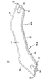
図1は、本発明の実施の形態1に係る液圧成形装置を説明するための断面図、図2は、図1に示される予備成形体を説明するための斜視図、図3は、本発明の実施の形態1に係る成形品を説明するための斜視図である。
【0011】
実施の形態1に係る液圧成形装置は、金型40,45、軸押しポンチ50,60、軸押しシリンダ51,61を有する。
【0012】
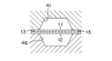
金型40,45は、予備成形体10を挟み込んで型締めするための上型および下型からなる。上型40および下型45は、近接離間可能であり、成形品30の外形形状に対応するキャビティ41,46が形成されている。
【0013】
予備成形体10は、重ね合せられた少なくとも2枚の板材11,12からなり、成形媒体が注入される液圧注入部14,15を有する。板材11,12の端部周辺は、接合部13を有する。接合部13は、例えば、溶接あるいは接着によって全周に形成されており、気密性が確保されている。溶接は、例えば、レーザー溶接や、アーク溶接である。
【0014】
予備成形体10を液圧成形することによって得られる成形品30は、例えば、自動車構造部材である。成形品30のフランジ部31は、予備成形体10における接合部13の近傍の部位からなるフランジ部16によって形成される。なお、符号31Aは、膨出変形に伴って外周方向に延伸する予備成形体10のフランジ部16Aによって形成される、成形品30の曲がっている箇所の内側のフランジ部である。
【0015】
軸押しポンチ50,60は、上型40および下型45の側面に配置され、軸押しシリンダ51,61に連結されている。軸押しポンチ50,60は、予備成形体10の液圧注入部14,15を経由して、例えば水からなる成形媒体を予備成形体10に供給するための注入ノズル52,62を有する。注入ノズル52,62の外周形状は、液圧注入部14,15の内周形状に対応している。
【0016】
注入ノズル52,62は、先端に形成される注入口53,63と、注入口53,63から内部を延長する成形媒体通路54,64とを有する。成形媒体通路54,64は、成形媒体タンクや圧力発生装置に連結された液圧回路(不図示)に接続されている。例えば、液圧回路には、圧力センサ、電磁バルブ、逆止弁等が適宜配置されている。
【0017】
軸押しシリンダ51,61は、軸押しポンチ50,60を、金型側に向かって進退自在に支持している。軸押しシリンダ51,61の駆動源は、例えば、油圧あるいは空圧である。
【0018】
なお、注入口53,63および成形媒体通路54,64は、成形媒体を抜き出す(除圧する)ためや、予備成形体10の内部に滞留している空気を排出するためにも使用される。
【0019】
図4は、図2に示されるフランジ部16Aを説明するための平面図、図5は、図4の線V−Vに関する断面図、図6は、フランジ部16Aを押圧する金型の当たり面の形状を説明するための、図4の線VI−VIに関する断面図である。
【0020】
膨出変形の際に外周方向に延伸するフランジ部16Aは、予備成形体10における接合部13の近傍の部位からなりかつ円弧状であり、外周方向に関して屈曲した断面形状を有するように、成形加工を施されている。つまり、フランジ部16Aは、外周方向(接合部13に沿った方向)に関して屈曲した断面形状を有する成形加工部位(成形加工が施された部位)21〜26を有する。
【0021】
したがって、予備成形体10の内部に成形媒体を供給して膨出変形させる際に、予備成形体10の接合部13が、キャビティ41,46に向かって引き込まれることで、フランジ部16Aは、外周方向に延伸するが、成形加工部位21〜26は、外周方向への延伸を吸収し、破断を抑制する。なお、屈曲した断面形状は、波形である。また、符号21A〜26Aは、成形加工部位21〜26の頂部(屈曲した断面形状の頂部)および頂部によって構成される稜線を示している。
【0022】
成形加工部位21〜26は、破断が想定されるライン20から離間して配置されており、膨出変形の際に、ライン20の近傍におけるキャビティ41,46に向かう材料流入を妨げない。したがって、キャビティ41,46の近傍に位置するフランジ部16Aの内側端部17における板厚の過度の減少が防がれる。なお、ライン20は、図4に示されるように、フランジ部16Aの中央位置を、フランジ部16Aの円弧中心から内側端部に向かう方向であるフランジ部の半径方向に、延長している。
【0023】
なお、内側に位置する成形加工部位23,24とライン20との間の離間距離D1は、フランジ部16Aの縁部端面において、例えば、板材11,12の板厚の約5倍である。また、成形加工部位21〜26は、ライン20を挟んだ両側に設けることに限定されず、一方の側のみに設けることも可能である。
【0024】
成形加工部位21〜26は、フランジ部16Aの半径方向(フランジ部16Aの円弧中心から内側端部17に向かう方向)に沿って配置されている。したがって、膨出変形の際に、外周方向への延伸を効率的に吸収すると共に、半径方向の材料流入を妨げない。
【0025】
成形加工部位21〜26の形状(屈曲した断面形状)は、フランジ部16Aの半径方向に沿って変化しており、フランジ部16Aの縁部端面において最大となっている。つまり、成形加工部位21〜26は、フランジ部16Aの縁部端面に向かって、徐々に大きくなる。
【0026】
この場合、膨出変形の際における外周方向への延伸が大きい部位においては、成形加工部位21〜26の形状も大きくなるため、外周方向への延伸を確実に吸収することができる。なお、フランジ部16Aの縁部端面における頂部21A〜26Aと板材11,12の重ね合わせ面との間の距離は、板材11,12の板厚の2倍以下が好ましい。
【0027】
フランジ部16Aの縁部端面の近傍における成形加工部位21〜26の屈曲した断面形状の曲率半径Rは、材料流入が終了したときの断面形状の曲率半径R1より、小さいことが好ましい。
【0028】
この場合、材料流入の終了時においても、フランジ部16Aの縁部端面の近傍における成形加工部位21〜26は、その形状を維持する。つまり、成形加工部位21〜26は、材料流入の開始時から終了時まで、外周方向への延伸を吸収する効果を確実に保持することが可能である。
【0029】
なお、材料流入が終了する液圧P1は、予備成形体10の膨出する頂部が、キャビティ41,46に接触する際に付加される液圧であり、例えば、最終液圧P2の30%以下の値である。最終液圧P2は、目的とする成形品30のコーナー部の曲率半径に対応して決定される。また、曲率半径R1は、定数kと板材11,12の引張強度Tsの積を液圧P1によって除した値に、板材11,12の板厚tを加算することによって算出される。
【0030】
型閉めによってフランジ部16Aを押圧する上型40および下型45の当たり面42,47は、成形加工部位21〜26の稜線21A〜26Aに対して、正の勾配を有する。つまり、上型40の当たり面42と成形加工部位21,23,24,26の稜線21A,23A,24A,26Aとがなす角度θと、下型45の当たり面47と成形加工部位22,25の稜線22A,25Aとがなす角度θは、正の値である。
【0031】
したがって、上型40および下型45の当たり面42,47は、膨出変形の際に、成形加工部位21〜26による外周方向の延伸の吸収および半径方向の材料流入を妨げない。なお、フランジ部16Aの縁部端面の近傍における成形加工部位21〜26と当たり面42,47との間のクリアランスD2は、接合部13の引き剥がれを抑制するためには、板材11,12の合計板厚の15%以下であることが好ましい。
【0032】
次に、予備成形体10が適用される液圧成形方法を説明する。図7は、型締め時を説明するための断面図、図8は、図7の線VIII−VIIIに関する断面図、図9は、液圧成形の初期を説明するための断面図、図10は、液圧成形の初期におけるフランジ部の膨出変形を説明するための斜視図、図11は、図9に続く,膨出変形過程を説明するための断面図、図12は、液圧成形の終了時を説明するための断面図である。
【0033】
まず、予備成形体10のフランジ部16Aに、例えば、プレスによる成形加工を施し、成形加工部位21〜26を形成する。成形加工後の予備成形体10は、上型30および下型35を有する金型によって、挟み込まれて型締めされる。
【0034】
その後、軸押しシリンダ51,61が、軸押しポンチ50,60を金型側に押し込める(図7および図8参照)。予備成形体10の液圧注入部14,15は、軸押しポンチ50,60により拡張されると共に、上型30および下型35により拡張が規制される。そのため、予備成形体10の液圧注入部14,15は、軸押しポンチ50,60に密着して、予備成形体10の気密性が確保される。
【0035】
そして、成形媒体が、成形媒体通路54,64を経由し、注入口53,63から予備成形体10の内部に供給される。その結果、予備成形体10に液圧が付加され、予備成形体10の膨出変形が開始する(図9参照)。
【0036】
この際、予備成形体10の接合部13が、キャビティ41,46に向かって引き込まれるため、接合部13の近傍の部位からなりかつ予備成形体10の曲がっている箇所の内側のフランジ部16Aは、外周方向に延伸する。しかし、フランジ部16Aは、外周方向に関して屈曲した断面形状を有する成形加工部位21〜26を有するため、外周方向への延伸が吸収される(図10参照)。したがって、外周方向への延伸がライン20に集中しないため、ライン20の近傍における破断が抑制される。
【0037】
また、キャビティ41,46に向かう材料流入は、妨げられないため、キャビティ41,46の近傍に位置するフランジ部16Aの内側端部17における板厚の過度の減少が防がれる。
【0038】
そして、成形媒体の供給が継続され、予備成形体10に付加される液圧が上昇し、予備成形体10の膨出する頂部18が、キャビティ41,46に接触することで、材料流入が終了する(図11参照)。
【0039】
なお、フランジ部16Aの縁部端面の近傍における成形加工部位21〜26の曲率半径Rが、材料流入が終了する液圧P1のときの断面形状の曲率半径R1より小さい場合、材料流入の終了時においても、その形状が維持されるため、外周方向への延伸を吸収する効果を確実に保持することが可能である。
【0040】
その後、材料流入が終了する液圧P1から最終液圧P2に到達すると(図12参照)、液圧の上昇が停止され、所定時間保持されることで、液圧成形が完了する(図12参照)。
【0041】
除圧後、型開きされ、成形品30が金型から取り出され、両端に形成されている液圧注入部14,15が、適宜切除される。
【0042】
以上のように、本実施の形態においては、膨出変形の際に外周方向に延伸する、予備成形体の接合部の近傍の部位からなりかつ円弧状であるフランジ部に対して、外周方向に関して屈曲した断面形状を有するように、前もって成形加工が施される。
【0043】
そのため、予備成形体の内部に成形媒体を供給し、接合部が、金型のキャビティに向かって引き込まれ、フランジ部の延伸を生じさせる際に、成形加工が施された部位は、外周方向への延伸を吸収し、フランジ部における破断を抑制する。つまり、本実施の形態は、膨出変形の際における破断を抑制し得る液圧成形方法を提供することが可能である。
【図面の簡単な説明】
【図1】 本発明の実施の形態1に係る液圧成形装置を説明するための断面図である。
【図2】 図1に示される予備成形体を説明するための斜視図である。
【図3】 本発明の実施の形態1に係る成形品を説明するための斜視図である。
【図4】 図1に示される予備成形体のフランジ部を説明するための平面図である。
【図5】 図4の線V−Vに関する断面図である。
【図6】 フランジ部を押圧する金型の当たり面の形状を説明するための、図4の線VI−VIに関する断面図である。
【図7】 型締め時を説明するための断面図である。
【図8】 図7の線VIII−VIIIに関する断面図である。
【図9】 液圧成形の初期を説明するための断面図である。
【図10】 液圧成形の初期におけるフランジ部の膨出変形を説明するための斜視図である。
【図11】 図9に続く,膨出変形過程を説明するための断面図である。
【図12】 液圧成形の終了時を説明するための断面図である。
【符号の説明】
10…予備成形体、
11,12…板材、
13…接合部、
14,15…液圧注入部、
16,16A…フランジ部、
17…内側端部、
18…頂部、
20…ライン、
21〜26…成形加工部位(成形加工が施された部位)、
21A〜26A…頂部(稜線)、
30…成形品、
31,31A…フランジ部、
40…上型、
41…キャビティ、
42…当たり面、
45…下型、
46…キャビティ、
47…当たり面、
50,60…軸押しポンチ、
51,61…軸押しシリンダ、
52,62…注入ノズル、
53,63…注入口、
54,64…成形媒体通路、
D1…離間距離、
D2…クリアランス、
P1,P2…液圧、
R,R1…曲率半径、
θ…角度。[0001]
BACKGROUND OF THE INVENTION
The present invention relates to a hydroforming method.
[0002]
[Prior art]
In a conventional hydraulic forming method, a preform is formed by bulging and deforming a preform by supplying a high-pressure forming medium to a preform formed of two metal plates whose edges are welded. A molded product is obtained (see, for example, Patent Document 1).
[0003]
[Patent Document 1]
Japanese Patent Laid-Open No. 11-347643
[Problems to be solved by the invention]
However, when a flange portion extending in the outer circumferential direction is formed with the material inflow due to the bulging deformation, there is a problem that a portion in the vicinity of the edge surface of the flange portion, for example, a heat-affected portion of the welded portion easily breaks. .
[0005]
On the other hand, when suppressing material inflow, it is possible to avoid breakage in the vicinity of the edge of the edge, but the reduction in the thickness of the portion adjacent to the cavity of the mold is promoted, and the portion is likely to break. Cause problems.
[0006]
The present invention has been made in order to solve the problems associated with the above-described prior art, and an object thereof is to provide a hydraulic forming method capable of suppressing breakage during bulging deformation.
[0007]
[Means for Solving the Problems]
To achieve the above object, the present invention provides:
A preform formed by joining the periphery of the stacked plates is sandwiched between molds having cavities corresponding to the outer shape of the molded product and clamped, and a molding medium is supplied to the preform. by adding a hydraulic pressure and, the preform a hydroforming method for bulging deformation,
The preform has a flange portion that is recessed in an arc shape in the vicinity of the joint portion of the plate material ,
The flange portion is subjected to molding so as to have a cross-sectional shape bent with respect to the outer peripheral direction along the joint portion of the preform,
Thereafter, the by supplying the molding medium in the interior of the preform, when causing bulging deforming the preform in the cavity, a flange portion recessed in said arcuate is drawn toward the cavity Rukoto said flange portion extending in the outer circumferential direction of the caused by a hydroforming method characterized by absorption by site where the molding processing is performed.
[0008]
【The invention's effect】
In the present invention configured as described above , the flange portion that is formed in the vicinity of the joint portion of the preform and has an arc shape that extends in the outer peripheral direction during bulging deformation is a cross-section that is bent with respect to the outer peripheral direction. It has a molding part having a shape. Therefore, when the forming medium is supplied into the preform and the joint is drawn toward the cavity of the mold , causing the flange to stretch , the molding site absorbs stretching in the outer circumferential direction. And suppressing breakage. That is, it is possible to provide a hydraulic forming method capable of suppressing breakage during bulging deformation.
[0009]
DETAILED DESCRIPTION OF THE INVENTION
Hereinafter, embodiments of the present invention will be described with reference to the drawings.
[0010]
1 is a cross-sectional view for explaining a hydraulic forming apparatus according to Embodiment 1 of the present invention, FIG. 2 is a perspective view for explaining a preformed body shown in FIG. 1, and FIG. It is a perspective view for demonstrating the molded article which concerns on Embodiment 1 of invention.
[0011]
The hydraulic forming apparatus according to the first embodiment includes dies 40 and 45,
[0012]
The
[0013]
The
[0014]
The molded
[0015]
The
[0016]
The
[0017]
The
[0018]
The
[0019]
4 is a plan view for explaining the
[0020]
The
[0021]
Therefore, when the molding medium is supplied into the preformed
[0022]
The forming
[0023]
Incidentally, the distance D 1 of the between the
[0024]
The forming
[0025]
The shapes (bent cross-sectional shapes) of the forming
[0026]
In this case, since the shape of the
[0027]
The curvature radius R of the bent cross-sectional shape of the
[0028]
In this case, even at the end of the material inflow, the
[0029]
Incidentally, the hydraulic pressure P 1 which material inflow is completed, the top bulging of the
[0030]
The contact surfaces 42 and 47 of the
[0031]
Therefore, the contact surfaces 42 and 47 of the
[0032]
Next, a hydraulic forming method to which the
[0033]
First, the
[0034]
Thereafter, the
[0035]
Then, the forming medium is supplied into the
[0036]
At this time, since the
[0037]
Moreover, since the material inflow toward the
[0038]
Then, the supply of the forming medium is continued, the hydraulic pressure applied to the preformed
[0039]
Incidentally, the
[0040]
Thereafter, when the final hydraulic pressure P 2 is reached from the hydraulic pressure P 1 at which the material inflow ends (see FIG. 12), the increase in the hydraulic pressure is stopped and held for a predetermined time, thereby completing the hydraulic molding (see FIG. 12).
[0041]
After depressurization, the mold is opened, the molded
[0042]
As described above, in the present embodiment, with respect to the outer circumferential direction with respect to the flange portion that is formed in the vicinity of the joint portion of the preform and has an arc shape, extending in the outer circumferential direction at the time of bulging deformation. A molding process is performed in advance so as to have a bent cross-sectional shape.
[0043]
Therefore, when the molding medium is supplied to the inside of the preform and the joint portion is drawn toward the cavity of the mold and the flange portion is stretched, the portion subjected to the molding process is in the outer circumferential direction. Is absorbed and the breakage at the flange portion is suppressed. That is, this embodiment can provide a hydraulic forming method that can suppress breakage during bulging deformation.
[Brief description of the drawings]
FIG. 1 is a cross-sectional view for explaining a hydraulic forming apparatus according to a first embodiment of the present invention.
FIG. 2 is a perspective view for explaining the preform shown in FIG.
FIG. 3 is a perspective view for explaining a molded product according to Embodiment 1 of the present invention.
4 is a plan view for explaining a flange portion of the preform shown in FIG. 1. FIG.
5 is a cross-sectional view taken along line VV in FIG.
6 is a cross-sectional view taken along line VI-VI in FIG. 4 for explaining the shape of the contact surface of the mold that presses the flange portion.
FIG. 7 is a cross-sectional view for explaining mold clamping.
8 is a cross-sectional view taken along line VIII-VIII in FIG.
FIG. 9 is a cross-sectional view for explaining the initial stage of hydroforming.
FIG. 10 is a perspective view for explaining the bulging deformation of the flange portion at the initial stage of hydroforming.
FIG. 11 is a cross-sectional view for explaining the bulging deformation process continued from FIG. 9;
FIG. 12 is a cross-sectional view for explaining the end of hydraulic forming.
[Explanation of symbols]
10 ... preformed body,
11, 12 ... board material,
13 ... Junction part,
14, 15 ... hydraulic pressure injection part,
16, 16A ... flange part,
17 ... inner end,
18 ... the top,
20 ... line,
21-26 ... molding process part (part where the molding process was given),
21A-26A ... Top (ridgeline),
30 ... molded product,
31, 31A ... flange portion,
40 ... Upper mold,
41 ... cavity,
42 ... Hit face,
45 ... Lower mold,
46 ... cavity,
47.
50, 60 ... Axial push punch,
51, 61 ... axial push cylinder,
52, 62 ... injection nozzle,
53, 63 ... inlet,
54, 64 ... molding medium passage,
D 1 ... separation distance,
D 2 ... clearance,
P 1 , P 2 ... hydraulic pressure,
R, R 1 ... radius of curvature,
θ ... An angle.
Claims (8)
前記予備成形体は、前記板材の接合部の近傍部位で円弧状に窪んだフランジ部を有し、
前記フランジ部に対して、前記予備成形体の接合部に沿った外周方向に関して屈曲した断面形状を有するように、成形加工を施し、
その後、前記予備成形体の内部に前記成形媒体を供給することにより、前記予備成形体をキャビティ内で膨出変形させる際、前記円弧状に窪んだフランジ部が前記キャビティに向かって引き込まれることによって生じる前記フランジ部の外周方向の延伸を、前記成形加工が施された部位により吸収する
ことを特徴とする液圧成形方法。A preform formed by joining the periphery of the stacked plates is sandwiched between molds having cavities corresponding to the outer shape of the molded product and clamped, and a molding medium is supplied to the preform. by adding a hydraulic pressure and, the preform a hydroforming method for bulging deformation,
The preform has a flange portion that is recessed in an arc shape in the vicinity of the joint portion of the plate material ,
The flange portion is subjected to molding so as to have a cross-sectional shape bent with respect to the outer peripheral direction along the joint portion of the preform,
Thereafter, the by supplying the molding medium in the interior of the preform, when causing bulging deforming the preform in the cavity, a flange portion recessed in said arcuate is drawn toward the cavity Rukoto The fluid pressure molding method is characterized in that the outer peripheral direction stretching of the flange portion caused by the above is absorbed by the part subjected to the molding process.
Priority Applications (1)
| Application Number | Priority Date | Filing Date | Title |
|---|---|---|---|
| JP2003166372A JP4333224B2 (en) | 2003-06-11 | 2003-06-11 | Hydraulic forming method |
Applications Claiming Priority (1)
| Application Number | Priority Date | Filing Date | Title |
|---|---|---|---|
| JP2003166372A JP4333224B2 (en) | 2003-06-11 | 2003-06-11 | Hydraulic forming method |
Publications (2)
| Publication Number | Publication Date |
|---|---|
| JP2005000942A JP2005000942A (en) | 2005-01-06 |
| JP4333224B2 true JP4333224B2 (en) | 2009-09-16 |
Family
ID=34092558
Family Applications (1)
| Application Number | Title | Priority Date | Filing Date |
|---|---|---|---|
| JP2003166372A Expired - Fee Related JP4333224B2 (en) | 2003-06-11 | 2003-06-11 | Hydraulic forming method |
Country Status (1)
| Country | Link |
|---|---|
| JP (1) | JP4333224B2 (en) |
Families Citing this family (1)
| Publication number | Priority date | Publication date | Assignee | Title |
|---|---|---|---|---|
| KR102750537B1 (en) * | 2019-05-02 | 2025-01-06 | 현대자동차 주식회사 | Part manufaturing method using hydroforming device |
-
2003
- 2003-06-11 JP JP2003166372A patent/JP4333224B2/en not_active Expired - Fee Related
Also Published As
| Publication number | Publication date |
|---|---|
| JP2005000942A (en) | 2005-01-06 |
Similar Documents
| Publication | Publication Date | Title |
|---|---|---|
| KR100488097B1 (en) | Metallic Sheet Hydroforming Method, Forming Die, and Formed Part | |
| JP3646695B2 (en) | Hydraulic forming apparatus and method for forming hollow structure parts made of laminated plate material, and laminated plate material | |
| JP7043496B2 (en) | Methods and Semi-Products for Producing At least Partially Hardened Variant Components | |
| JP5245755B2 (en) | Press-molded product, press-molded product manufacturing method and manufacturing apparatus | |
| JP4333224B2 (en) | Hydraulic forming method | |
| JP4581473B2 (en) | Hydraulic molding method and hydraulic molding apparatus | |
| JP5609749B2 (en) | Method for producing hydraulic bulge molded product made of metal plate, hydraulic bulge molding die, and hydraulic bulge molded product | |
| JP4924222B2 (en) | Method and apparatus for hydraulic forming of laminated plate material | |
| JP4066846B2 (en) | Liquid pressure forming method of laminated plate material | |
| JP4092488B2 (en) | Liquid pressure forming method and liquid pressure forming apparatus | |
| JP4281463B2 (en) | Hydraulic molding method and hydraulic molding apparatus | |
| JP4590956B2 (en) | Hydraulic forming method | |
| JP4131332B2 (en) | Hydraulic forming method | |
| JP2006255750A (en) | Metal structural member and method for manufacturing the same | |
| JP2020131231A (en) | Manufacturing method of hydroformed products | |
| JP4706213B2 (en) | Pre-formed body, hydraulic molding method and hydraulic molded product | |
| JP4622624B2 (en) | Pre-formed body, hydraulic forming method and hydraulic forming member | |
| JP4016847B2 (en) | Hydraulic forming apparatus and hydraulic forming method | |
| JP4670334B2 (en) | Pre-formed body, hydraulic molding method and hydraulic molded product | |
| JP2005254286A (en) | Hydraulic forming apparatus and hydraulic forming method | |
| JP4661141B2 (en) | Preliminary body for hydroforming and hydroforming method | |
| JP2005238254A (en) | Extruded aluminum material for hydraulic forming and its hydraulic forming method | |
| JP2006026646A (en) | Hydraulic molding method and hydraulic molding apparatus | |
| JP2002096116A (en) | Method and apparatus for forming hydroformed laminated plate and laminated plate | |
| JP2005000978A (en) | Hydroforming method and hydroforming metal plate |
Legal Events
| Date | Code | Title | Description |
|---|---|---|---|
| A621 | Written request for application examination |
Free format text: JAPANESE INTERMEDIATE CODE: A621 Effective date: 20060424 |
|
| A977 | Report on retrieval |
Free format text: JAPANESE INTERMEDIATE CODE: A971007 Effective date: 20070413 |
|
| A131 | Notification of reasons for refusal |
Free format text: JAPANESE INTERMEDIATE CODE: A131 Effective date: 20070501 |
|
| A521 | Written amendment |
Free format text: JAPANESE INTERMEDIATE CODE: A523 Effective date: 20070628 |
|
| A131 | Notification of reasons for refusal |
Free format text: JAPANESE INTERMEDIATE CODE: A131 Effective date: 20071218 |
|
| A521 | Written amendment |
Free format text: JAPANESE INTERMEDIATE CODE: A523 Effective date: 20080215 |
|
| A131 | Notification of reasons for refusal |
Free format text: JAPANESE INTERMEDIATE CODE: A131 Effective date: 20080909 |
|
| A521 | Written amendment |
Free format text: JAPANESE INTERMEDIATE CODE: A523 Effective date: 20081020 |
|
| TRDD | Decision of grant or rejection written | ||
| A01 | Written decision to grant a patent or to grant a registration (utility model) |
Free format text: JAPANESE INTERMEDIATE CODE: A01 Effective date: 20090602 |
|
| A01 | Written decision to grant a patent or to grant a registration (utility model) |
Free format text: JAPANESE INTERMEDIATE CODE: A01 |
|
| A61 | First payment of annual fees (during grant procedure) |
Free format text: JAPANESE INTERMEDIATE CODE: A61 Effective date: 20090615 |
|
| FPAY | Renewal fee payment (event date is renewal date of database) |
Free format text: PAYMENT UNTIL: 20120703 Year of fee payment: 3 |
|
| R150 | Certificate of patent or registration of utility model |
Free format text: JAPANESE INTERMEDIATE CODE: R150 |
|
| LAPS | Cancellation because of no payment of annual fees |