JP4335273B2 - Drinking water server - Google Patents
Drinking water server Download PDFInfo
- Publication number
- JP4335273B2 JP4335273B2 JP2007202877A JP2007202877A JP4335273B2 JP 4335273 B2 JP4335273 B2 JP 4335273B2 JP 2007202877 A JP2007202877 A JP 2007202877A JP 2007202877 A JP2007202877 A JP 2007202877A JP 4335273 B2 JP4335273 B2 JP 4335273B2
- Authority
- JP
- Japan
- Prior art keywords
- water
- storage tank
- container
- water storage
- tank
- Prior art date
- Legal status (The legal status is an assumption and is not a legal conclusion. Google has not performed a legal analysis and makes no representation as to the accuracy of the status listed.)
- Expired - Fee Related
Links
- 239000003651 drinking water Substances 0.000 title claims description 175
- 235000020188 drinking water Nutrition 0.000 title claims description 174
- XLYOFNOQVPJJNP-UHFFFAOYSA-N water Substances O XLYOFNOQVPJJNP-UHFFFAOYSA-N 0.000 claims description 439
- 238000010438 heat treatment Methods 0.000 claims description 17
- 230000007423 decrease Effects 0.000 claims description 14
- 239000007788 liquid Substances 0.000 claims description 7
- 239000000463 material Substances 0.000 claims description 7
- 238000007599 discharging Methods 0.000 claims description 4
- 235000013361 beverage Nutrition 0.000 claims 2
- 230000008602 contraction Effects 0.000 claims 2
- 239000011347 resin Substances 0.000 description 42
- 229920005989 resin Polymers 0.000 description 42
- 238000001816 cooling Methods 0.000 description 8
- 238000000034 method Methods 0.000 description 5
- 230000000694 effects Effects 0.000 description 4
- NJPPVKZQTLUDBO-UHFFFAOYSA-N novaluron Chemical compound C1=C(Cl)C(OC(F)(F)C(OC(F)(F)F)F)=CC=C1NC(=O)NC(=O)C1=C(F)C=CC=C1F NJPPVKZQTLUDBO-UHFFFAOYSA-N 0.000 description 3
- 238000012856 packing Methods 0.000 description 2
- 235000012206 bottled water Nutrition 0.000 description 1
- 239000004020 conductor Substances 0.000 description 1
- 229910052500 inorganic mineral Inorganic materials 0.000 description 1
- 230000014759 maintenance of location Effects 0.000 description 1
- 239000011707 mineral Substances 0.000 description 1
- 239000003507 refrigerant Substances 0.000 description 1
Images



Classifications
-
- B—PERFORMING OPERATIONS; TRANSPORTING
- B67—OPENING, CLOSING OR CLEANING BOTTLES, JARS OR SIMILAR CONTAINERS; LIQUID HANDLING
- B67D—DISPENSING, DELIVERING OR TRANSFERRING LIQUIDS, NOT OTHERWISE PROVIDED FOR
- B67D1/00—Apparatus or devices for dispensing beverages on draught
- B67D1/08—Details
- B67D1/12—Flow or pressure control devices or systems, e.g. valves, gas pressure control, level control in storage containers
- B67D1/14—Reducing valves or control taps
-
- F—MECHANICAL ENGINEERING; LIGHTING; HEATING; WEAPONS; BLASTING
- F25—REFRIGERATION OR COOLING; COMBINED HEATING AND REFRIGERATION SYSTEMS; HEAT PUMP SYSTEMS; MANUFACTURE OR STORAGE OF ICE; LIQUEFACTION SOLIDIFICATION OF GASES
- F25D—REFRIGERATORS; COLD ROOMS; ICE-BOXES; COOLING OR FREEZING APPARATUS NOT OTHERWISE PROVIDED FOR
- F25D31/00—Other cooling or freezing apparatus
- F25D31/005—Combined cooling and heating devices
-
- B—PERFORMING OPERATIONS; TRANSPORTING
- B67—OPENING, CLOSING OR CLEANING BOTTLES, JARS OR SIMILAR CONTAINERS; LIQUID HANDLING
- B67D—DISPENSING, DELIVERING OR TRANSFERRING LIQUIDS, NOT OTHERWISE PROVIDED FOR
- B67D1/00—Apparatus or devices for dispensing beverages on draught
- B67D1/08—Details
- B67D1/12—Flow or pressure control devices or systems, e.g. valves, gas pressure control, level control in storage containers
- B67D1/14—Reducing valves or control taps
- B67D2001/1488—Reducing valves or control taps pneumatically operated
-
- B—PERFORMING OPERATIONS; TRANSPORTING
- B67—OPENING, CLOSING OR CLEANING BOTTLES, JARS OR SIMILAR CONTAINERS; LIQUID HANDLING
- B67D—DISPENSING, DELIVERING OR TRANSFERRING LIQUIDS, NOT OTHERWISE PROVIDED FOR
- B67D3/00—Apparatus or devices for controlling flow of liquids under gravity from storage containers for dispensing purposes
- B67D3/0009—Apparatus or devices for controlling flow of liquids under gravity from storage containers for dispensing purposes provided with cooling arrangements
-
- B—PERFORMING OPERATIONS; TRANSPORTING
- B67—OPENING, CLOSING OR CLEANING BOTTLES, JARS OR SIMILAR CONTAINERS; LIQUID HANDLING
- B67D—DISPENSING, DELIVERING OR TRANSFERRING LIQUIDS, NOT OTHERWISE PROVIDED FOR
- B67D3/00—Apparatus or devices for controlling flow of liquids under gravity from storage containers for dispensing purposes
- B67D3/0022—Apparatus or devices for controlling flow of liquids under gravity from storage containers for dispensing purposes provided with heating arrangements
-
- F—MECHANICAL ENGINEERING; LIGHTING; HEATING; WEAPONS; BLASTING
- F25—REFRIGERATION OR COOLING; COMBINED HEATING AND REFRIGERATION SYSTEMS; HEAT PUMP SYSTEMS; MANUFACTURE OR STORAGE OF ICE; LIQUEFACTION SOLIDIFICATION OF GASES
- F25D—REFRIGERATORS; COLD ROOMS; ICE-BOXES; COOLING OR FREEZING APPARATUS NOT OTHERWISE PROVIDED FOR
- F25D2323/00—General constructional features not provided for in other groups of this subclass
- F25D2323/122—General constructional features not provided for in other groups of this subclass the refrigerator is characterised by a water tank for the water/ice dispenser
Landscapes
- Engineering & Computer Science (AREA)
- Chemical & Material Sciences (AREA)
- Combustion & Propulsion (AREA)
- Physics & Mathematics (AREA)
- Mechanical Engineering (AREA)
- Thermal Sciences (AREA)
- General Engineering & Computer Science (AREA)
- Devices For Dispensing Beverages (AREA)
Description
この発明は、容器に収容されたミネラルウォーター等の飲料水をタンク内に貯留した後、その貯留した飲料水を常温又は冷温で、あるいは、その貯留した飲料水を加熱して適宜供給できるようにした飲料水用サーバーに関するものである。 In the present invention, after drinking water such as mineral water stored in a container is stored in a tank, the stored drinking water can be supplied at room temperature or cold temperature, or the stored drinking water can be appropriately supplied by heating. It relates to a drinking water server.
従来の飲料水用サーバーは、例えば、図5(a)に示すように、貯水タンク10から上方に伸びる導水管11に容器1が着脱可能であり、その容器1内の飲料水wが、その自重により、導水管11を通じて貯水タンク10内へ流下するようになっている。
For example, as shown in FIG. 5 (a), a conventional drinking water server is configured such that a
この容器1は硬質の樹脂等で成型されており、予め殺菌処理等が施された状態の飲料水wが、例えば、20リットル程度の単位で封入されて、密閉された状態で市場に供給されているものである。容器1が硬質の樹脂で成型されているため、内部の飲料水wが減少してもその形状が維持される。
The
図5(b)に示すように、容器1内の飲料水wが貯水タンク10に向かって徐々に流下していくとともに、容器1内には導水管11を通じて徐々に貯水タンク10内の空気aが入り込んでいき、その容器1内の気圧が平常に保たれる。同時に、貯水タンク10内の空気aは、飲料水wが流入することにより通気口13から外部に排出される。
As shown in FIG. 5 (b), the drinking water w in the
貯水タンク10内の水位が、図5(c)に示すように導水管11の下端に達すると、容器1への空気aの流入が止まる。このため、自重により流下しようとする飲料水wの流下圧により容器1内がいわゆる負圧状態となり、それ以上の飲料水wの流下を不可能とする。すなわち、貯水タンク10内の液面に作用する空気圧と、容器1内の液面に作用する空気圧とのバランスにより、容器1内から貯水タンク10への水の流下が自動的に止まるようになっている。
When the water level in the
また、その貯水タンク10から送水管21が引き出されており、その送水管21に開閉自在の供給バルブ20が設けられている。
供給バルブ20を開放すれば、貯水タンク10内の飲料水wが適宜外部へ供給でき、また、供給バルブ20を閉鎖すれば、その供給が止まるようになっている。
A
If the
また、この送水管21からの飲料水wの供給により、貯水タンク10内の水位が低下すれば、図5(d)に示すように、その水位が導水管11の下端に達して前記空気圧のバランスが取れる状態になるまで、容器1内の飲料水wが貯水タンク10内に流下し、貯水タンク10内の水位が維持される。
Further, if the water level in the
また、図6に示すように、軟質の樹脂等、可撓性を有する素材で形成した容器1を使用する飲料水用サーバーもある。
この容器1は、前述の硬質の樹脂を用いた容器1と同様、予め殺菌処理等が施された状態の飲料水wが、例えば、20リットル程度の単位で封入されて、密閉された状態で市場に供給されているものである。容器1が軟質の樹脂で成型されているため、内部の飲料水wが減少すると、それに応じて変形し内部の容積が収縮するようになっている。
In addition, as shown in FIG. 6, there is a drinking water server that uses a
As in the case of the
この飲料水用サーバーの作用を説明すると、図6(a)に示すように取付けた容器1内の飲料水wが、前記貯水タンク10内へ流下してその容器1内の飲料水wが減少すると、前記容器1は収縮変形してその容器1内に空気が侵入しないようになっている(図6(b)参照)。図中の符号15は通気孔を示し、符号16は、その通気孔15に設けられるフィルタを示す。
Explaining the operation of this drinking water server, the drinking water w in the
導水管11の下端に設けたフロート弁14が、貯水タンク10内の水位変動に伴ってその導水管11の下端開口を開閉するようになっている。
このため、容器1内から貯水タンク10への水の流下は、貯水タンク10内の水位が上昇して所定の位置に達した際に、フロート弁14が導水管11の下端開口を閉じることにより、自動的に止まるようになっている(図6(c)参照)。
A
For this reason, the flow of water from the
また、送水管21からの飲料水wの供給により、貯水タンク10内の水位が低下すれば、フロート弁14が導水管11の下端開口を開放することにより、容器1内の飲料水wが貯水タンク10内に流下し、その水位が維持される(図6(d)参照)。
Moreover, if the water level in the
すなわち、この飲料水用サーバーでは、可撓性を有する容器1を用いていることから、その容器1内に空気aが入り込まないことを前提としている。このため、前述の硬質の容器1を用いた飲料水用サーバーとは異なり、容器1に通じる導水管11を弁を用いて直接開閉することにより、飲料水wの流下を制御しているのである。
That is, in this drinking water server, since the
なお、一般的には、貯水タンク10に冷却装置(図示せず)を設けて、貯水タンク10内の飲料水を冷却して冷水として供給する場合が多いといえる。
In general, it can often be said that a cooling device (not shown) is provided in the
また、図7に示すように、加熱した飲料水w(飲料水h)を供給できるようにした飲料水用サーバーもある。
この飲料水用サーバーは、前記貯水タンク10の下方に加熱装置31を備えた温水タンク30を設け、その温水タンク30と前記貯水タンク10とが給水管32で接続されている。
貯水タンク10内の飲料水wがその給水管32を通じて前記温水タンク30内へ流下するようになっており、温水タンク30内の飲料水wは加熱装置31によって加熱される。
Moreover, as shown in FIG. 7, there is also a drinking water server that can supply heated drinking water w (drinking water h).
In this drinking water server, a
The drinking water w in the
前記温水タンク30から第二送水管25が引き出されており、その第二送水管25に開閉自在の第二供給バルブ24が設けられている。
このため、第二供給バルブ24を開放すれば、温水タンク30内の飲料水w(加熱された「飲料水w」を、以下「飲料水h」を記載する。)が適宜外部へ供給でき、また、第二供給バルブ24を閉鎖すれば、その供給が止まるようになっている(例えば、特許文献1参照)。
A second
For this reason, if the
なお、貯水タンク10に設けられる送水管21、供給バルブ20を省略して、加熱された「飲料水h」のみを供給するようにした飲料水用サーバーもある。
There is also a drinking water server in which the
上記の図5に示す飲料水用サーバーによれば、樹脂製容器1内、あるいは貯水タンク10内の飲料水wが、常に、空気aに触れた状態となる。
飲料水wは、できる限り空気aに触れないことが、衛生管理上望ましいといえる。
According to the drinking water server shown in FIG. 5, the drinking water w in the
It can be said that it is desirable for hygiene management that the drinking water w does not touch the air a as much as possible.
この点、図6に示す飲料水用サーバーによれば、樹脂製容器1内には空気aが入らないので、より好ましいといえる。
しかし、貯水タンク10内の飲料水wが空気aに触れることは避けられない。
In this regard, the drinking water server shown in FIG. 6 is more preferable because air a does not enter the
However, it is inevitable that the drinking water w in the
また、図7に示す飲料水用サーバーによれば、温水タンク30内の飲料水hは温度が高いので、その飲料水hが加熱とともに膨張して、給水管32内を逆流して上昇することがある。
Moreover, according to the drinking water server shown in FIG. 7, since the drinking water h in the
加熱された飲料水(温水)hが給水管32内を逆流すると、図7に示すように、その給水管32の貯水タンク10側の開口部32aから加熱された飲料水hが貯水タンク10内に入り込み、貯水タンク10内の飲料水wの温度を上昇させてしまう。また、その給水管32の管体そのものが熱伝導体として機能し、貯水タンク10内の飲料水wの温度を上昇させてしまう場合もある。この傾向は、貯水タンク10に冷却装置を備えた場合、両タンク10,30内の飲料水w、hの温度差が大きくなるので、より顕著である。
本来、加熱されるべきでない貯水タンク10内の飲料水wの温度が上昇することは、飲料水wの管理上望ましくない。
When the heated drinking water (warm water) h flows backward in the
It is not desirable for the management of the drinking water w that the temperature of the drinking water w in the
そこで、この発明は、飲料水が空気に触れることを極力抑制することを第一の課題とし、加熱した飲料水を供給できるようにした飲料水用サーバーにあっては、貯水タンク内の飲料水の温度上昇を抑制することを第二の課題とする。 In view of this, the first object of the present invention is to suppress drinking water from touching air as much as possible, and in a drinking water server that can supply heated drinking water, drinking water in a water storage tank is provided. The second problem is to suppress the temperature rise.
上記第一の課題を解決するために、この発明は、貯水タンクから上方に伸びる導水管に容器が着脱可能であり、前記容器内の飲料水がその導水管を通じて貯水タンク内へ流下するようになっており、その貯水タンクから送水管を引き出してその送水管に開閉自在の供給バルブを設けてその貯水タンク内の飲料水を供給できるようにし、前記容器は可撓性を有する素材で形成され、前記容器内の飲料水が前記貯水タンク内へ流下してその容器内の飲料水が減少する際に、前記容器は収縮変形してその樹脂製容器内に空気が侵入しないようになっている飲料水用サーバーにおいて、前記貯水タンク内の上端に空気弁を設け、その空気弁を介して前記貯水タンク内の空気を排出することにより前記容器内の飲料水を流下させて、その貯水タンク内を満水状態に維持できるようにした構成を採用した。 In order to solve the first problem, the present invention is such that a container can be attached to and detached from a water conduit extending upward from a water storage tank, and drinking water in the container flows into the water storage tank through the water conduit. The water supply pipe is pulled out from the water storage tank, and an openable / closable supply valve is provided in the water supply pipe so that drinking water in the water storage tank can be supplied. The container is formed of a flexible material. When the drinking water in the container flows down into the water storage tank and the drinking water in the container decreases, the container shrinks and deforms so that air does not enter the resin container. In the drinking water server, an air valve is provided at an upper end in the water storage tank, and the water in the water storage tank is discharged through the air valve to cause the water in the container to flow down. The Employing the configuration to be able to maintain the water state.
このように、容器に通じる導水管を開閉するのではなく、貯水タンク内の上端に設けた空気弁を介して容器からの飲料水の流下を制御できるようにしたので、その空気弁から空気を排出させれば貯水タンク内を満水状態に維持できる。このため、容器内のみならず、貯水タンク内の飲料水も空気に触れることを極力抑制できるようになる。 In this way, the flow of drinking water from the container can be controlled via the air valve provided at the upper end in the water storage tank, rather than opening and closing the water conduit leading to the container. If discharged, the inside of the water storage tank can be kept full. For this reason, not only the inside of the container but also the drinking water in the water storage tank can be suppressed as much as possible.
すなわち、容器は、内部の飲料水の減少に伴って収縮変形してその容器の内部に空気が侵入しないようになっているので、貯水タンク内の飲料水の上方に空気が介在する場合において、その空気を空気弁を介して排出すると、その空気の排出とともに、容器内に空気を混入させることなく飲料水をさらに貯水タンク内へ流下させ、その貯水タンクを常に満水状態に維持することができる。
ここで、満水状態とは、貯水タンク内の空気が完全に無くなるまで、あるいは、仮に、僅かな空気が介在するとしても空気がほぼ完全になくなった状態に近い状態を意味し、上記の構成によれば、その満水状態になるまで、貯水タンク内に飲料水を充填することができるものである。
That is, since the container shrinks and deforms as the drinking water inside decreases so that air does not enter the container, when air is present above the drinking water in the water storage tank, When the air is discharged through the air valve, the drinking water can flow down into the water storage tank without mixing air into the container, and the water storage tank can always be kept full. .
Here, the full water state means a state in which the air in the water storage tank is completely exhausted, or even if a slight amount of air is present, the state is almost the state in which the air has almost completely disappeared. According to this, the water storage tank can be filled with drinking water until the water is full.
なお、前記空気弁は、手動操作により開閉を行い、適宜のタイミングで貯水タンク内に介在する空気の排出を行うようにした構成を採用してもよいが、例えば、空気弁として、貯水タンク内の水位の変動に伴って昇降するフロート弁体によって開閉される構成を採用すれば、そのフロート弁の昇降により自動的に空気の排出を行うことができるので便利である。 The air valve may be configured to open and close by manual operation, and to discharge air intervening in the water storage tank at an appropriate timing. Adopting a structure that is opened and closed by a float valve element that moves up and down with the fluctuation of the water level is convenient because air can be automatically discharged by raising and lowering the float valve.
また、上記第二の課題を解決するために、この発明は、前記貯水タンクの下方に加熱装置を備えた温水タンクを設け、その温水タンクと前記貯水タンクとが給水管で接続されて、前記貯水タンク内の飲料水がその給水管を通じて加熱タンク内へ流下するようになっており、前記加熱タンクから第二送水管を引き出してその第二送水管に開閉自在の第二供給バルブを設けてその加熱タンク内の飲料水を供給できるようにし、前記給水管を、前記貯水タンクの上部又は前記導水管に接続した構成を採用した。 In order to solve the second problem, the present invention provides a hot water tank provided with a heating device below the water storage tank, the hot water tank and the water storage tank are connected by a water supply pipe, Drinking water in the water storage tank flows down into the heating tank through the water supply pipe, and a second supply valve that can be opened and closed is provided in the second water supply pipe by drawing out the second water supply pipe from the heating tank. The drinking water in the heating tank was supplied, and the water supply pipe was connected to the upper part of the water storage tank or the water conduit.
上記第一の課題を解決したことに伴い、貯水タンク内の飲料水は常に満水状態が維持できるようになっている。このため、貯水タンクと温水タンクとの給水管を、貯水タンクの上部又は導水管に接続した構成を採用できるようになった。
給水管を、貯水タンクの上部又はその貯水タンクから上方に伸びる導水管に接続できれば、給水管の長さが長くなるので、加熱された飲料水の逆流による貯水タンク内の飲料水の温度上昇、及び、その給水管そのものを通じた熱伝導による温度上昇を防ぐことができる。
この給水管は、温水タンクの下部から引き出せば、さらに給水管の長さを長くできるので、より好ましいといえる。
With the solution of the first problem, the drinking water in the water storage tank can always be kept full. For this reason, the structure which connected the water supply pipe of a water storage tank and a warm water tank to the upper part of a water storage tank or a water conduit came to be employable.
If the water supply pipe can be connected to the upper part of the water storage tank or a water guide pipe extending upward from the water storage tank, the length of the water supply pipe will be increased, so that the temperature rise of the drinking water in the water storage tank due to the reverse flow of heated drinking water, And the temperature rise by the heat conduction through the water supply pipe itself can be prevented.
If this water supply pipe is pulled out from the lower part of the hot water tank, the length of the water supply pipe can be further increased, which is more preferable.
また、貯水タンクと温水タンクとを繋ぐ給水管を、貯水タンクの上部又は導水管に接続した構成を採用できるようになったことにより、給水管を貯水タンク外に配管することができる。従来のように、給水管を貯水タンク内に入り込ませ、その中央部から取水する必要がないからである。
給水管が貯水タンク外に配管されていれば、その給水管と貯水タンクの上部又は前記導水管との接続部に開閉弁(閉止バルブ)を設けることが容易である。貯水タンク外であれば、開閉弁の操作、取付けが容易であり、また、その開閉弁の装置として汎用品を使用することができる。
In addition, since the water supply pipe connecting the water storage tank and the hot water tank can be connected to the upper part of the water storage tank or the water conduit, the water supply pipe can be piped outside the water storage tank. This is because it is not necessary to make the water supply pipe enter the water storage tank and take water from the central portion as in the conventional case.
If the water supply pipe is provided outside the water storage tank, it is easy to provide an open / close valve (closing valve) at the connection between the water supply pipe and the water storage tank or the water conduit. If it is outside the water storage tank, it is easy to operate and attach the on-off valve, and a general-purpose product can be used as the on-off valve device.
このように開閉弁(閉止バルブ)を設けるのは、以下の理由によるものである。
すなわち、従来、貯水タンクと温水タンクとを併設した飲料水用サーバーにおいて、例えば、夏場など温水を使用しない時期には、加熱装置を作動しないようにするとともに、温水タンクからの飲料水の供給を止める場合が多かった。このとき、そのままでは温水タンク内に長期に亘り飲料水が滞留することとなってしまうので、給水管の途中に開閉弁(閉止バルブ)を設けて温水タンクに水が流下しないようにしていた。
The reason for providing the on-off valve (closing valve) in this way is as follows.
That is, conventionally, in a drinking water server provided with a water storage tank and a hot water tank, for example, during periods when hot water is not used, such as in summer, the heating device is not activated and drinking water is supplied from the hot water tank. There were many cases to stop. At this time, since the drinking water stays in the hot water tank for a long time as it is, an on-off valve (closing valve) is provided in the middle of the water supply pipe so that the water does not flow into the hot water tank.
しかし、給水管の上端が貯水タンク内に入り込んでいる場合、その給水管の上端に開閉弁を設けることが困難であるため、開閉弁を給水管の途中に設けることを余儀なくされていた。開閉弁を給水管の途中に設けると、その給水管の上端と開閉弁との間に水の滞留(いわゆる「死に水」)が生じさせるので好ましくない。
そこで、上記のように給水管を、貯水タンクの上部又は前記導水管に接続したことにより、その給水管の上端近くに開閉弁を設けることが可能となったものである。このようにすれば、給水管内の水の滞留をより確実に排除することができる。
However, when the upper end of the water supply pipe has entered the water storage tank, it is difficult to provide an open / close valve at the upper end of the water supply pipe, and thus the open / close valve has to be provided in the middle of the water supply pipe. If the on-off valve is provided in the middle of the water supply pipe, water retention (so-called “dead water”) is generated between the upper end of the water supply pipe and the on-off valve.
Therefore, by connecting the water supply pipe to the upper part of the water storage tank or the water guide pipe as described above, an open / close valve can be provided near the upper end of the water supply pipe. In this way, the retention of water in the water supply pipe can be more reliably eliminated.
なお、貯水タンクに設けられる送水管、供給バルブを省略して、温水タンクを通じて、加熱された飲料水のみを供給するようにした飲料水用サーバーもある。 There is also a drinking water server in which a water supply pipe and a supply valve provided in a water storage tank are omitted and only heated drinking water is supplied through a hot water tank.
その構成は、貯水タンクから上方に伸びる導水管に容器が着脱可能であり、前記容器内の飲料水がその導水管を通じて貯水タンク内へ流下するようになっており、前記貯水タンクの下方に加熱装置を備えた温水タンクを設け、その温水タンクと前記貯水タンクとが給水管で接続されて、前記貯水タンク内の飲料水がその給水管を通じて前記温水タンク内へ流下するようになっており、前記温水タンクから送水管を引き出してその送水管に開閉自在の供給バルブを設けてその温水タンク内の飲料水を供給できるようにし、前記容器は可撓性を有する素材で形成され、前記容器内の飲料水が前記貯水タンク内へ流下してその容器内の飲料水が減少する際に、前記容器は収縮変形してその容器内に空気が侵入しないようになっている飲料水用サーバーにおいて、前記貯水タンク内の上端に空気弁を設け、その空気弁を介して前記貯水タンク内の空気を排出することにより前記容器内の飲料水を流下させて、その貯水タンク内を満水状態に維持できるようにしたことを特徴とする飲料水用サーバーである。 The structure is such that a container can be attached to and detached from a water conduit extending upward from the water storage tank, and the drinking water in the container flows into the water storage tank through the water conduit and is heated below the water storage tank. A hot water tank provided with a device is provided, the hot water tank and the water storage tank are connected by a water supply pipe, and the drinking water in the water storage tank flows into the hot water tank through the water supply pipe, A water supply pipe is pulled out from the hot water tank and an openable / closable supply valve is provided to the water supply pipe so that drinking water in the hot water tank can be supplied. The container is formed of a flexible material, When the drinking water flows down into the water storage tank and the drinking water in the container decreases, the container shrinks and deforms so that air does not enter the container. In this case, an air valve is provided at the upper end of the water storage tank, and the water in the water storage tank is discharged through the air valve to cause the drinking water in the container to flow down, so that the water storage tank is filled with water. A drinking water server characterized in that it can be maintained.
なお、上記の各構成における飲料水用サーバーを用いれば、容器が内部の飲料水の減少に伴って収縮変形してその容器の内部に空気が侵入しないようになっていることから、次なる飲料水の供給方法を採用することができる。 If the drinking water server in each of the above configurations is used, the container is contracted and deformed as the drinking water in the container decreases, so that air does not enter the container. A water supply method can be employed.
すなわち、貯水タンク内の飲料水の上方に空気が介在する場合において、その空気を貯水タンクの上部に設けた空気弁を介して排出すると、その空気の排出とともに、容器内に空気を混入させることなく飲料水をさらに貯水タンク内へ流下させ、その貯水タンクを満水状態に維持する飲料水の供給方法である。 That is, when air is present above the drinking water in the water storage tank, if the air is discharged through an air valve provided at the top of the water storage tank, the air is mixed into the container along with the air being discharged. This is a drinking water supply method in which drinking water is further flowed down into a water storage tank and the water storage tank is maintained in a full state.
なお、貯水タンクに貯留した飲料水は、その貯水タンクから引き出した送水管、その送水管に設けた開閉自在の供給バルブを介して外部に供給する供給方法を採用してもよいし、それに代えて、あるいはそれに加えて、貯水タンク内の飲料水をその下方に設けた温水タンクに導いて、その温水タンク内で加熱された飲料水を、その温水タンクから引き出した送水管、その送水管に設けた開閉自在の供給バルブを介して外部に供給する供給方法を採用してもよい。
すなわち、この供給方法を採用することにより、貯水タンク内の空気が完全に無くなるまで、あるいは、仮に、僅かな空気が介在するとしても空気がほぼ完全になくなった状態に近い状態になるまで、貯水タンク内に飲料水を充填することができる。したがって、貯水タンクを常に満水の状態に維持できるようになる。
In addition, the drinking water stored in the water storage tank may adopt a supply method of supplying to the outside through a water supply pipe drawn from the water storage tank and an openable / closable supply valve provided in the water supply pipe. Or in addition thereto, the drinking water in the water storage tank is led to a hot water tank provided below, and the drinking water heated in the hot water tank is drawn into the water pipe and the water pipe drawn from the hot water tank. You may employ | adopt the supply method supplied to the exterior through the provided openable / closable supply valve.
That is, by adopting this supply method, until the air in the water storage tank is completely exhausted, or even if a slight amount of air is interposed, the water is stored until the air is almost completely exhausted. The tank can be filled with drinking water. Therefore, the water storage tank can always be kept full.
この発明は、以上のようにしたので、飲料水が空気に触れることを極力抑制することができ、また、加熱した飲料水を供給できるようにした飲料水用サーバーにあっては、貯水タンク内の飲料水の温度上昇を抑制することができる。 Since the present invention has been described above, it is possible to suppress the drinking water from touching the air as much as possible, and in the drinking water server that can supply the heated drinking water, The rise in the temperature of drinking water can be suppressed.
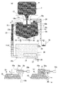
この発明の実施形態を図面に基づいて説明する。この実施形態の飲料水用サーバーは、図2に示すように、冷却装置29を備えた貯水タンク10から上方に伸びる導水管11に樹脂製容器(容器)1が着脱可能であり、その樹脂製容器1内の飲料水wが、その自重により、導水管11を通じて貯水タンク10内へ流下するようになっている。
An embodiment of the present invention will be described with reference to the drawings. In the drinking water server of this embodiment, as shown in FIG. 2, a resin container (container) 1 can be attached to and detached from a
樹脂製容器1及び貯水タンク10は、それぞれ、図1に示す飲料水用サーバー2の容器収納部3、及び本体4の内部に収容されている。その貯水タンク10から送水管21が引き出されて本体4外へ伸びており、その送水管21に開閉自在の供給バルブ20が設けられている(図2参照)。
供給バルブ20を開放すれば、貯水タンク10内の飲料水wが、図1に示す供給部5から、適宜外部のコップやペットボトル等の容器へ供給でき、また、供給バルブ20を閉鎖すれば、その供給が止まるようになっている。その供給バルブ20の開閉は、前記供給部5に設けたレバー操作により可能である。
The
If the
また、この飲料水用サーバー2には、前記貯水タンク10の下方に加熱装置31を備えた温水タンク30が設けられており、その温水タンク30と前記貯水タンク10とが給水管32で接続されている。この給水管32は、前記貯水タンク10の上部と温水タンク30の下部とに接続されている。
The
この給水管32を通じて、貯水タンク10内の飲料水wが、その自重により、前記温水タンク30内へ流下するようになっている。なお、冷却装置29は、例えば、パイプ内に冷媒が流れるなどして貯水タンク10内の飲料水wを冷却する機能を備えた周知の冷却手段を採用でき、また、加熱装置31は、通電によって温水タンク30内の飲料水wを加熱する機能を備えた電熱器等を採用し得る。
Through this
この温水タンク30及び加熱装置31等も、それぞれ、図1に示す飲料水用サーバー2の本体4の内部に収容されている。その温水タンク30から側方へ第二送水管25が引き出されて本体4外へ伸びており、その第二送水管25に開閉自在の第二供給バルブ24が設けられている。
The
第二供給バルブ20を開放すれば、温水タンク10内の加熱された飲料水hが、図1に示す供給部6から、適宜外部のコップやペットボトル等の容器へ供給でき、また、供給バルブ24を閉鎖すれば、その供給が止まるようになっている。その第二供給バルブ24の開閉は、同じく、前記供給部6に設けたレバー操作により可能である。
If the
なお、貯水タンク10及び温水タンク30の底部には、それぞれ排出バルブ22,26付きの排出管23,27が設けられている。排出バルブ22,26は、ともに、通常は閉鎖状態に維持される。排出バルブ22,26をそれぞれ開放することにより、貯水タンク10及び温水タンク30の底部に沈殿した異物等を、内部の飲料水wとともに外部に排出できる。
なお、貯水タンク10や温水タンク30の底部を、例えば、図2に示す貯水タンク10のように、下方に向かうにつれて徐々に狭まるテーパー状として、前記排出管23,27をそのテーパ状の底部の最下端部に開口して設ければ、異物の排出効果がさらに高まるといえる。
Note that the bottom of the
内部に飲料水wを収容した樹脂製容器1は、予め殺菌処理等が施された状態の飲料水wが封入されて密閉された状態で市場に供給されているものであり、その樹脂製容器1の開口部に、前記貯水タンク10から上方に伸びる導水管11を差し込み可能である。
The
この樹脂製容器1の着脱構造としては、周知の構造を採用してよいが、この実施形態では、上記のように、樹脂製容器1の開口部内に前記導水管11を差し込むように取付けることにより、樹脂製容器1が台座17によって支えられるとともに、その開口部と導水管11との間の液密がパッキン等により維持されるようになっている。
このため、樹脂製容器1内の飲料水wが周囲にこぼれることなく、導水管11を通じて貯水タンク10内へ自重により流下するようになっている。
As the attachment / detachment structure of the
For this reason, the drinking water w in the
なお、上記のように、樹脂製容器1の開口部内周と導水管11外周との間は液密が維持されているが、仮に、わずかにこぼれた飲料水wがあった場合、その飲料水wは、台座17の凹部17aの底に設けた排出路18a,18cを通じて受け部19へ排出されるようになっている。このため、台座17の凹部17a内にこぼれた水が滞留することがない。
As described above, the liquid tightness is maintained between the inner periphery of the opening of the
また、前記樹脂製容器1は可撓性を有する樹脂で形成されている。このため、前記樹脂製容器1の開口部を下向きにしてその開口部内に前記導水管11を差し込むと、内部の飲料水wが、その自重により貯水タンク10内へ自然に流下していく。このとき、樹脂製容器1内の飲料水wの減少とともに、樹脂製容器1は、その内部の容積が減少するよう収縮変形し、その樹脂製容器1内に空気が侵入しないようになっている。
The
さらに、前記貯水タンク10内の上端に空気弁28が設けられている。この空気弁28は、貯水タンク10の上端に設けた凸部10aに臨むように設けられ、図2(b)(c)に示すように、バネ等の弾性部材の付勢力によって弁体28aが閉弁方向に付勢されている。また、その付勢力に抗して、弁軸(操作部)28bを手で押すことにより弁体28aが開弁方向へ移動するようになっている。
Further, an
このため、前記貯水タンク10内に貯留された飲料水wの液面上に空気aが介在し、その空気aが凸部10a内に入り込んでいる場合において、弁軸(操作部)28bを手で押せば、これらの空気aを空気弁28を介して外部へ排出できるようになっている。なお、空気弁28は、凸部10a内に介在する空気aを残らず排出できるよう、凸部10a内の最上部に臨むことが望ましい。
For this reason, when the air a is interposed on the liquid level of the drinking water w stored in the
この飲料水用サーバー2の作用を説明すると、貯水タンク10内に飲料水wが全くない状態において、樹脂製容器1を導水管11に差し込んで台座17に樹脂製容器1を固定する。樹脂製容器1内の飲料水wが、その自重により、徐々に貯水タンク10内へ流下していくとともに、樹脂製容器1は収縮変形していく。
飲料水wの流下により貯水タンク10内の空気圧が上昇すれば、その空気圧の上昇により飲料水wの流下が自動的に一時停止する。このとき、空気弁28を開放して内部の空気aを貯水タンク10外に排出させれば、再度飲料水wの流下が開始する。
このため、貯水タンク10内にある程度の量の飲料水wが溜まるまで、空気弁28を一定の時間、開放状態に維持しておいてもよいし、あるいは、飲料水wの流下状況を見ながら、流下が止まればその都度空気弁28を開放するなど、断続的に開放操作を行ってもよい。
The operation of this
If the air pressure in the
For this reason, the
このように、貯水タンク10内の水は徐々に水位を増していき、その水位が、給水管32の上端における貯水タンク10側の開口部32bに至ると、その給水管32を通じて温水タンク30へもその自重により流下していく。このとき、温水タンク30内においても、前記貯水タンク10と同様の空気aの排出操作を行う。すなわち、例えば、給水管32からの飲料水wの流下が停止した場合は、適宜、第二供給バルブ24を開放して内部の空気aを第二送水管25を通じて温水タンク30外に排出させるなどの操作を行う。
なお、この間、樹脂製容器1内の飲料水wがなくなれば、適宜、新しい飲料水w入りの樹脂製容器1に取替えてもよい。
In this way, the water level in the
During this time, if the drinking water w in the
温水タンク30と貯水タンク10とが満水となり、貯水タンク10内の水位が図2(b)に示す位置になると、貯水タンク10の上端に設けた凸部10a内に空気aが溜まった状態となり、この状態で、樹脂製容器1内から貯水タンク10への水の流下は自動的に止まる。
When the
この状態で、空気弁28を手動で操作して開弁させれば、その凸部10a内の空気aを排出路18b,18cを通じて外部の受け部19へ向かって排出できる。このとき、空気aに混ざって飲料水wも若干排出されるが、その量はわずかであるのでさしつかえない。
In this state, if the
このように空気aを排出すると、凸部10a内には、その空隙を埋めるように樹脂製容器1からさらに飲料水wが流下する。このため、貯水タンク10内の水位は、図2(c)に示すように満水状態、すなわち、空気aが全く介在しない状態、あるいは、介在したとしてもその量がほんの僅かな状態に至る。
このように、空気弁28の開閉を適宜操作することにより、貯水タンク10内を常に満水状態に維持することができる。
When the air a is discharged in this way, the drinking water w further flows down from the
As described above, by appropriately opening and closing the
なお、図1に示すように、給水管32が、貯水タンク10及び温水タンク30の外面に沿って配管されており、その給水管32と貯水タンク10の上部との接続部に開閉弁(閉止バルブ)33が設けられている。
このため、例えば、夏場など加熱された飲料水hの供給を行わない場合には、加熱装置31を作動しないようにするとともに、開閉弁33を閉鎖して温水タンク30に水が流下しないようにすることができる。すなわち、温水タンク30内を空の状態にすることができ、その温水タンク30内に長期に亘り飲料水wが滞留することを防止し得る。
As shown in FIG. 1, a
For this reason, for example, when the heated drinking water h is not supplied, such as in summer, the
この実施形態は、手動操作により開閉を行う空気弁28を採用したが、その空気弁28として、例えば、貯水タンク10内の水位の変動に伴って昇降するフロート弁体を採用してもよい。
In this embodiment, the
フロート弁体を採用する場合、貯水タンク10の上端付近に空気aが溜まると飲料水wの水位は満水状態よりもやや下がる(例えば、図2(a)に示す水位参照)ので、その水位の下降とともにフロート弁体も下降する。フロート弁体が下降すれば、空気弁28が開弁するので、前記空気aが外部へ排出される。空気aが排出されれば、貯水タンク10内の水位が上昇する(例えば、図2(b)に示す水位参照)ので、その水位の上昇によりフロート弁体も上昇し空気弁28を閉じ、満水状態で貯水タンク10を密閉することができる。
When the float valve body is used, the water level of the drinking water w is slightly lower than the full water level when the air a accumulates near the upper end of the water storage tank 10 (see, for example, the water level shown in FIG. 2A). The float valve body also descends as it descends. When the float valve body is lowered, the
また、上記の実施形態では、貯水タンク10と温水タンク30とを接続する給水管32上端の開口部32bを、貯水タンク10の上部、すなわち、貯水タンク10の上面を閉じる開閉自在の蓋10bを液密に閉じるパッキンpのすぐ下方に開口して設けている。
このため、従来と比較して、給水管32の長さを長く確保できるようになっている。給水管32が長いので、温水タンク30内で加熱された飲料水hの逆流による貯水タンク10内の飲料水wの温度上昇、及び、その給水管32の管体自体を通じた熱伝導による貯水タンク10内の飲料水wの温度上昇を防ぐことができる。
Moreover, in said embodiment, the
For this reason, compared with the past, the length of the
なお、給水管32は、貯水タンク10のできる限り上部に開口させることが望ましいが、例えば、貯水タンク10の上面を塞ぐ開閉自在の蓋10bに開口させても機能し得る。
また、給水管32下端における温水タンク30側への開口部32cは、給水管32を長くするために、温水タンク30のできる限り下部へ開口させることが望ましい。
The
In addition, the
他の実施形態を図3に示す。この実施形態は、上記の実施形態における給水管32を、貯水タンク10から上方へ伸びる導水管11の途中に接続したものである。
この構成によれば、給水管32の長さがさらに長くなるので、加熱された飲料水hの逆流による貯水タンク10内の飲料水wの温度上昇を、より確実に防ぐことができる。
Another embodiment is shown in FIG. In this embodiment, the
According to this configuration, since the length of the
さらに他の実施形態を図4に示す。この実施形態は、温水タンク30、給水管32等を省略した構成である。貯水タンク10内に貯留された飲料水wが、送水管21、供給バルブ20を通じて供給できるようになっている。
また、貯水タンク10に設けられる空気弁28には、フロート弁が採用されているほか、主たる構成は、前述の実施形態と同様である。
Yet another embodiment is shown in FIG. In this embodiment, the
The
図4(a)に示す状態において、樹脂製容器1の開口部内に前記導水管11を差し込めば、樹脂製容器1は台座17によって支えられるとともに、樹脂製容器1内の飲料水wが、導水管11を通じて貯水タンク10内へ自重により自然に流下する。
In the state shown in FIG. 4A, if the
樹脂製容器1は可撓性を有する素材で形成されているので、樹脂製容器1内の飲料水wが徐々に減少する際に、その減少とともに樹脂製容器1は収縮変形し、樹脂製容器1内に空気が侵入しないようになっている点は、前述の各実施形態と同様である。
Since the
貯水タンク10内の飲料水wが徐々に水位を増していき、その間、貯水タンク10内の空気aは、図4(b)に示す矢印のように、空気弁28を介して外部に排出される。貯水タンク10内の水位が、図4(b)の位置を過ぎて図4(c)の位置になると、貯水タンク10の上端に設けた凸部10a内に溜まった空気aが残らず排出されて満水状態となり、空気弁28は閉弁して貯水タンク10が密閉状態となる。この状態で、樹脂製容器1内から貯水タンク10への飲料水wの流下は自動的に止まる。
The drinking water w in the
この状態で、樹脂製容器1等から貯水タンク10内にわずかに空気aが入り込んだ場合、あるいは、貯水タンク10内にわずかに空気aが残っている場合、その空気弁28の操作部28bを手動で下方へ押し込んで操作すれば、フロート弁体が下がり空気弁28が開弁するので、凸部10a内の空気aを排出路18b,18cを通じて外部へ排出できる。
In this state, when a little air a enters the
なお、空気弁28を介して空気aを排出すると、凸部10a内には、その空隙を埋めるように樹脂製容器1からさらに飲料水wが流下するので、貯水タンク10内を常に満水状態に維持することができる点も、前述の実施形態と同様である。
When air a is discharged through the
なお、上記各実施形態において、貯水タンク10に設けられる冷却装置29は、必要に応じて選択的に備えることができる。
In each of the above embodiments, the
1 容器(樹脂製容器)
2 飲料水用サーバー
3 容器収納部
4 本体
5 飲料水供給部(常温水)
6 飲料水供給部(温水)
10 貯水タンク
10a 凸部
11 導水管
14,28 フロート弁
13,15 通気孔
16 フィルタ
17 台座
17a 凹部
18a,18b,18c 排出路
19 受け部
20 供給バルブ
21 送水管
22,26 排出バルブ
23,27 排出管
24 第二供給バルブ(供給バルブ)
25 第二送水管(送水管)
28 空気弁
28a 弁体
28b 弁軸(操作部)
29 冷却装置
30 温水タンク
31 加熱装置
32 給水管
33 開閉弁
1 Container (resin container)
2
6 Drinking water supply section (hot water)
DESCRIPTION OF
25 Second water pipe (water pipe)
28
29
Claims (3)
前記貯水タンク(10)の上面を閉じる蓋(10b)に凸部(10a)を設け、前記凸部(10a)は、前記貯水タンク(10)内に上方へ突出する空間を形成するとともに、前記蓋(10b)は、前記導水管(11)の前記貯水タンク(10)内への開口よりも上方に位置し、
前記貯水タンク(10)に、前記凸部(10a)内の空間に臨む空気弁(28)を設け、その空気弁(28)は、前記貯水タンク(10)内に貯留された飲料水(w)の液面上に空気(a)が介在し、その空気(a)が前記凸部(10a)内に入り込んでいる場合において、その空気弁(28)を開放してその貯水タンク(10)内の空気(a)を前記貯水タンク(10)外へ排出することにより、その空気(a)の排出に伴う前記貯水タンク(10)内の空隙を埋めるように前記容器(1)内の飲料水(w)を流下させて前記容器(1)を収縮変形させる機能を有し、その飲料水(w)の流下及び前記容器(1)を収縮変形により、前記貯水タンク(10)内を空気(a)のない満水状態に維持できるようにしたことを特徴とする飲料水用サーバー。 Conduit extending from the water storage tank (10) upwards (11) the container (1) are possible removable, drinking water in the container (1) (w) is the conduit (11) through the water storage tank (10) adapted to flow down the inner, the water storage tank (10) from a water pipe (21) is pulled out the water pipes (21) that the water storage tank provided with openable supply valve (20) to (10) to allow the supply of drinking water (w), the container (1) is formed of a flexible material, flow down into the container (1) in drinking water (w) is the water storage tank (10) to when the drinking water of the container (1) in (w) decreases, the container (1) the water conduit in the container (1) in contracted deformed so that the internal volume is reduced (11 ) so air (a) it does not enter from the side In drinking water are server,
The lid (10b) for closing the upper surface of the water storage tank ( 10 ) is provided with a convex portion (10a), and the convex portion (10a) forms a space protruding upward in the water storage tank (10), and The lid (10b) is located above the opening of the water conduit (11) into the water storage tank (10),
The water tank (10) is provided with an air valve ( 28 ) facing the space in the convex portion (10a), and the air valve ( 28 ) is used for drinking water (w) stored in the water tank (10). ) Is present on the liquid surface, and the air (a) enters the convex portion (10a), the air valve (28) is opened and the water storage tank ( 10 ). By discharging the air ( a ) in the water tank (10) out of the water tank (10 ) , the beverage in the container ( 1 ) is filled so as to fill the gap in the water tank (10) as the air (a) is discharged. water (w) and passed down a function to shrink deforming the container (1), the air by a stream and contraction deformation of the container (1) of the drinking water (w), the water storage tank (10) It is characterized in that to be able to maintain, if not full level of (a) For drinking water server.
前記貯水タンク(10)内の上端に空気弁(28)を設け、その空気弁(28)を介して前記貯水タンク(10)内の空気(a)を排出することにより前記容器(1)内の飲料水(w)を流下させて、その貯水タンク(10)内を満水状態に維持できるようにし、
前記貯水タンク(10)の下方に加熱装置(31)を備えた温水タンク(30)を設け、その温水タンク(30)と前記貯水タンク(10)とが給水管(32)で接続されて、前記貯水タンク(10)内の飲料水(w)がその給水管(32)を通じて前記温水タンク(30)内へ流下するようになっており、前記温水タンク(30)から第二送水管(25)を引き出してその第二送水管(25)に開閉自在の第二供給バルブ(24)を設けてその温水タンク(30)内の飲料水(w,h)を供給できるようにし、
前記給水管(32)を、前記貯水タンク(10)の上部に接続し、前記給水管(32)を前記貯水タンク(10)外に上下方向に配管し、その給水管(32)と前記貯水タンク(10)の上部との接続部に開閉弁(33)を設けたことを特徴とする飲料水用サーバー。 Conduit extending from the water storage tank (10) upwards (11) the container (1) are possible removable, drinking water in the container (1) (w) is the conduit (11) through the water storage tank (10) adapted to flow down the inner, the water storage tank (10) from a water pipe (21) is pulled out the water pipes (21) that the water storage tank provided with openable supply valve (20) to (10) to allow the supply of drinking water (w), the container (1) is formed of a flexible material, flow down into the container (1) in drinking water (w) is the water storage tank (10) to when the drinking water of the container (1) in (w) decreases, the container (1) server for drinking water which is adapted to the air does not enter into the container (1) in contracted deformation In
The water storage tank (10) to the upper end of the provided air valve (28), the water storage tank the container (1) in by discharging (10) of the air (a) through the air valve (28) Of drinking water ( w ) so that the water storage tank ( 10 ) can be kept full ,
A hot water tank ( 30 ) provided with a heating device ( 31 ) is provided below the water storage tank ( 10 ) , the hot water tank ( 30 ) and the water storage tank ( 10 ) are connected by a water supply pipe ( 32 ) , the water storage tank (10) in drinking water (w) is controlled so as to flow down into the hot water tank (30) through the water supply pipe that (32), the second water supply pipe from the hot water tank (30) (25 ) And the second water supply pipe ( 25 ) is provided with a second supply valve ( 24 ) that can be freely opened and closed to supply drinking water ( w, h ) in the hot water tank ( 30 ) ,
The water supply tube (32), connected to the top of the water storage tank (10), the water supply pipe (32) the piping in the water storage tank (10) vertically outside and the reservoir and its water supply pipe (32) tank (10) top and drinking water for servers that wherein the opening and closing valve (33) provided on the connecting portion of the.
前記貯水タンク(10)の上面を閉じる蓋(10b)に凸部(10a)を設け、前記凸部(10a)は、前記貯水タンク(10)内に上方へ突出する空間を形成するとともに、前記蓋(10b)は、前記導水管(11)の前記貯水タンク(10)内への開口よりも上方に位置し、
前記貯水タンク(10)に、前記凸部(10a)内の空間に臨む空気弁(28)を設け、その空気弁(28)は、前記貯水タンク(10)内に貯留された飲料水(w)の液面上に空気(a)が介在し、その空気(a)が前記凸部(10a)内に入り込んでいる場合において、その空気弁(28)を開放してその貯水タンク(10)内の空気(a)を前記貯水タンク(10)外へ排出することにより、その空気(a)の排出に伴う前記貯水タンク(10)内の空隙を埋めるように前記容器(1)内の飲料水(w)を流下させて前記容器(1)を収縮変形させる機能を有し、その飲料水(w)の流下及び前記容器(1)を収縮変形により、前記貯水タンク(10)内を空気(a)のない満水状態に維持できるようにしたことを特徴とする飲料水用サーバー。 Conduit extending from the water storage tank (10) upwards (11) the container (1) are possible removable, drinking water in the container (1) (w) is the conduit (11) through the water storage tank (10) A hot water tank ( 30 ) provided with a heating device ( 31 ) is provided below the water storage tank ( 10 ) , and the hot water tank ( 30 ) and the water storage tank ( 10 ) Connected by a water supply pipe ( 32 ) , the drinking water ( w ) in the water storage tank ( 10 ) flows into the hot water tank ( 30 ) through the water supply pipe ( 32 ) , and the hot water tank The water pipe ( 25 ) is pulled out from ( 30 ) and an openable / closable supply valve ( 24 ) is provided in the water pipe ( 25 ) so that drinking water ( w, h ) in the hot water tank ( 30 ) can be supplied. The above Container (1) is formed of a flexible material, said container (1) in the drinking water (w) is the water storage tank (10) flows down into the container (1) in drinking water (w ) Decreases, the container ( 1 ) contracts and deforms so that the internal volume decreases, and air (a) does not enter the container ( 1 ) from the water conduit (11) side. Drinking water servers
The lid (10b) for closing the upper surface of the water storage tank ( 10 ) is provided with a convex portion (10a), and the convex portion (10a) forms a space protruding upward in the water storage tank (10), and The lid (10b) is located above the opening of the water conduit (11) into the water storage tank (10),
The water tank (10) is provided with an air valve ( 28 ) facing the space in the convex portion (10a), and the air valve ( 28 ) is used for drinking water (w) stored in the water tank (10). ) Is present on the liquid surface, and the air (a) enters the convex portion (10a), the air valve (28) is opened and the water storage tank ( 10 ). By discharging the air ( a ) in the water tank (10) out of the water tank (10 ) , the beverage in the container ( 1 ) is filled so as to fill the gap in the water tank (10) as the air (a) is discharged. water (w) and passed down a function to shrink deforming the container (1), the air by a stream and contraction deformation of the container (1) of the drinking water (w), the water storage tank (10) It is characterized in that to be able to maintain, if not full level of (a) For drinking water server.
Priority Applications (3)
| Application Number | Priority Date | Filing Date | Title |
|---|---|---|---|
| JP2007202877A JP4335273B2 (en) | 2007-08-03 | 2007-08-03 | Drinking water server |
| KR1020080003797A KR101174310B1 (en) | 2007-08-03 | 2008-01-14 | Drinking water server and method of feeding drinking water using the server |
| TW097129046A TWI441771B (en) | 2007-08-03 | 2008-07-31 | Beverage water feeder |
Applications Claiming Priority (1)
| Application Number | Priority Date | Filing Date | Title |
|---|---|---|---|
| JP2007202877A JP4335273B2 (en) | 2007-08-03 | 2007-08-03 | Drinking water server |
Publications (2)
| Publication Number | Publication Date |
|---|---|
| JP2009035322A JP2009035322A (en) | 2009-02-19 |
| JP4335273B2 true JP4335273B2 (en) | 2009-09-30 |
Family
ID=40437602
Family Applications (1)
| Application Number | Title | Priority Date | Filing Date |
|---|---|---|---|
| JP2007202877A Expired - Fee Related JP4335273B2 (en) | 2007-08-03 | 2007-08-03 | Drinking water server |
Country Status (3)
| Country | Link |
|---|---|
| JP (1) | JP4335273B2 (en) |
| KR (1) | KR101174310B1 (en) |
| TW (1) | TWI441771B (en) |
Families Citing this family (14)
| Publication number | Priority date | Publication date | Assignee | Title |
|---|---|---|---|---|
| JP4317262B1 (en) * | 2009-03-30 | 2009-08-19 | 株式会社コスモライフ | Beverage dispenser |
| JP5388186B2 (en) * | 2009-04-10 | 2014-01-15 | 恒久 千葉 | Drinking water supply device |
| JP4824105B2 (en) * | 2009-08-11 | 2011-11-30 | 株式会社フジヤマ | Liquid storage device |
| JP5059135B2 (en) | 2010-01-22 | 2012-10-24 | 株式会社フジヤマ | Drinking water server |
| WO2012157129A1 (en) * | 2011-05-18 | 2012-11-22 | 橋本精工 株式会社 | Air vent structure for container and water server using same |
| WO2012164759A1 (en) * | 2011-05-27 | 2012-12-06 | 橋本精工 株式会社 | Liquid supply structure of container, and water server using same |
| JP5059963B1 (en) * | 2011-10-17 | 2012-10-31 | 橋本精工 株式会社 | Air bleeding structure of container and water server using the same |
| JP5917885B2 (en) * | 2011-11-02 | 2016-05-18 | パーパス株式会社 | Water server |
| JP5069810B1 (en) * | 2012-05-31 | 2012-11-07 | 橋本精工 株式会社 | Air bleeding structure of container and water server using the same |
| JP2014008980A (en) * | 2012-06-28 | 2014-01-20 | Mt Fuji Springs Inc | Water supplier in which drinking water from water pack is taken in lower cold water tank and hot water tank by gravity |
| JP5538482B2 (en) * | 2012-06-28 | 2014-07-02 | 富士山の銘水株式会社 | Water supply machine using a water bag filled with drinking water in a plastic film bag |
| JP6041756B2 (en) * | 2013-05-29 | 2016-12-14 | 株式会社フジヤマ | Container adapter |
| TWI720198B (en) * | 2016-05-30 | 2021-03-01 | 日商目的股份有限公司 | Water dispenser and air valve |
| CN108883924B (en) * | 2016-05-30 | 2020-07-28 | 目的株式会社 | Drinking machine |
Family Cites Families (2)
| Publication number | Priority date | Publication date | Assignee | Title |
|---|---|---|---|---|
| JP2003128194A (en) * | 2001-10-16 | 2003-05-08 | Toshiba Electric Appliance Co Ltd | Drinking water server |
| JP3768217B2 (en) * | 2003-09-24 | 2006-04-19 | 株式会社東海公司 | Beverage server |
-
2007
- 2007-08-03 JP JP2007202877A patent/JP4335273B2/en not_active Expired - Fee Related
-
2008
- 2008-01-14 KR KR1020080003797A patent/KR101174310B1/en not_active Expired - Fee Related
- 2008-07-31 TW TW097129046A patent/TWI441771B/en not_active IP Right Cessation
Also Published As
| Publication number | Publication date |
|---|---|
| KR101174310B1 (en) | 2012-08-16 |
| TWI441771B (en) | 2014-06-21 |
| TW200925099A (en) | 2009-06-16 |
| JP2009035322A (en) | 2009-02-19 |
| KR20090014078A (en) | 2009-02-06 |
Similar Documents
| Publication | Publication Date | Title |
|---|---|---|
| JP2009035322A (en) | Server for drinking water | |
| CN102365228B (en) | Beverage dispenser | |
| US6588630B2 (en) | Continuous-flow drinking fluid dispenser | |
| JP4824105B2 (en) | Liquid storage device | |
| CN102471045B (en) | Beverage server | |
| JP6084484B2 (en) | Water server | |
| JP4630913B2 (en) | Server for drinking water and exhaust means for water storage tank used in the server for drinking water | |
| JP5059135B2 (en) | Drinking water server | |
| JP6041756B2 (en) | Container adapter | |
| GB2302394A (en) | Ball cock valve regulator | |
| CN105783403A (en) | Refrigerator | |
| JP4859850B2 (en) | Drinking water server | |
| US8474407B2 (en) | Poultry watering system and method | |
| JP3170068U (en) | Server structure for drinking water | |
| JP5558971B2 (en) | Liquid storage device | |
| JP2012071900A (en) | Server for potable water | |
| CN2571305Y (en) | Enclosed type water dispenser | |
| JP7133169B2 (en) | water server | |
| CN106037475A (en) | Pipeline machine | |
| JPH11344141A (en) | Expandable drink feeding valve | |
| KR20120038223A (en) | Hot-cold purifiers | |
| JP3089451U (en) | Drinking water supply | |
| JP2008178439A (en) | Beverage extraction container | |
| WO2020235656A1 (en) | Beverage server | |
| JP2026054612A (en) | Refrigerator with integrated bottled water dispenser |
Legal Events
| Date | Code | Title | Description |
|---|---|---|---|
| A621 | Written request for application examination |
Free format text: JAPANESE INTERMEDIATE CODE: A621 Effective date: 20081205 |
|
| A131 | Notification of reasons for refusal |
Free format text: JAPANESE INTERMEDIATE CODE: A131 Effective date: 20090310 |
|
| A521 | Request for written amendment filed |
Free format text: JAPANESE INTERMEDIATE CODE: A523 Effective date: 20090428 |
|
| TRDD | Decision of grant or rejection written | ||
| A01 | Written decision to grant a patent or to grant a registration (utility model) |
Free format text: JAPANESE INTERMEDIATE CODE: A01 Effective date: 20090616 |
|
| A01 | Written decision to grant a patent or to grant a registration (utility model) |
Free format text: JAPANESE INTERMEDIATE CODE: A01 |
|
| A61 | First payment of annual fees (during grant procedure) |
Free format text: JAPANESE INTERMEDIATE CODE: A61 Effective date: 20090624 |
|
| FPAY | Renewal fee payment (event date is renewal date of database) |
Free format text: PAYMENT UNTIL: 20120703 Year of fee payment: 3 |
|
| R150 | Certificate of patent or registration of utility model |
Free format text: JAPANESE INTERMEDIATE CODE: R150 Ref document number: 4335273 Country of ref document: JP Free format text: JAPANESE INTERMEDIATE CODE: R150 |
|
| FPAY | Renewal fee payment (event date is renewal date of database) |
Free format text: PAYMENT UNTIL: 20130703 Year of fee payment: 4 |
|
| R250 | Receipt of annual fees |
Free format text: JAPANESE INTERMEDIATE CODE: R250 |
|
| R250 | Receipt of annual fees |
Free format text: JAPANESE INTERMEDIATE CODE: R250 |
|
| R250 | Receipt of annual fees |
Free format text: JAPANESE INTERMEDIATE CODE: R250 |
|
| R250 | Receipt of annual fees |
Free format text: JAPANESE INTERMEDIATE CODE: R250 |
|
| R250 | Receipt of annual fees |
Free format text: JAPANESE INTERMEDIATE CODE: R250 |
|
| R250 | Receipt of annual fees |
Free format text: JAPANESE INTERMEDIATE CODE: R250 |
|
| R250 | Receipt of annual fees |
Free format text: JAPANESE INTERMEDIATE CODE: R250 |
|
| R250 | Receipt of annual fees |
Free format text: JAPANESE INTERMEDIATE CODE: R250 |
|
| R250 | Receipt of annual fees |
Free format text: JAPANESE INTERMEDIATE CODE: R250 |
|
| R250 | Receipt of annual fees |
Free format text: JAPANESE INTERMEDIATE CODE: R250 |
|
| LAPS | Cancellation because of no payment of annual fees |