JP4338532B2 - Communication device - Google Patents
Communication device Download PDFInfo
- Publication number
- JP4338532B2 JP4338532B2 JP2004001794A JP2004001794A JP4338532B2 JP 4338532 B2 JP4338532 B2 JP 4338532B2 JP 2004001794 A JP2004001794 A JP 2004001794A JP 2004001794 A JP2004001794 A JP 2004001794A JP 4338532 B2 JP4338532 B2 JP 4338532B2
- Authority
- JP
- Japan
- Prior art keywords
- phase difference
- time response
- response signal
- complex
- complex time
- Prior art date
- Legal status (The legal status is an assumption and is not a legal conclusion. Google has not performed a legal analysis and makes no representation as to the accuracy of the status listed.)
- Expired - Fee Related
Links
Images


Classifications
-
- H—ELECTRICITY
- H04—ELECTRIC COMMUNICATION TECHNIQUE
- H04B—TRANSMISSION
- H04B7/00—Radio transmission systems, i.e. using radiation field
- H04B7/01—Reducing phase shift
Landscapes
- Engineering & Computer Science (AREA)
- Computer Networks & Wireless Communication (AREA)
- Signal Processing (AREA)
- Mobile Radio Communication Systems (AREA)
- Monitoring And Testing Of Transmission In General (AREA)
- Cable Transmission Systems, Equalization Of Radio And Reduction Of Echo (AREA)
Description
本発明は通信装置に関し、特に無線通信を行う通信装置に関する。 The present invention relates to a communication apparatus, and more particularly to a communication apparatus that performs wireless communication.
近年、携帯電話をはじめとする移動体通信の加入者数は、爆発的に増加している。また、携帯電話は、音声通話だけでなく、インターネットとの融合を進めた複合機能を持つ端末としての比重が高くなっており、モバイル分野におけるマルチメディアサービスへの発展が期待されている。 In recent years, the number of mobile communication subscribers such as mobile phones has increased explosively. In addition, mobile phones are becoming more and more important as terminals having composite functions that are not only voice calls but also integrated with the Internet, and are expected to develop into multimedia services in the mobile field.
移動体通信では、移動局の移動に伴い、基地局と移動局の見通しは建物などにより遮られ、伝搬路特性は時々刻々変動する。このため、移動体通信技術では、伝搬路特性の変動に伴う通信品質劣化を克服することが重要なテーマになっている。 In mobile communication, as the mobile station moves, the line-of-sight characteristics of the base station and the mobile station are interrupted by buildings and the propagation path characteristics change from moment to moment. For this reason, overcoming communication quality degradation associated with fluctuations in propagation path characteristics has become an important theme in mobile communication technologies.
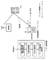
図20は基地局と移動端末間の伝搬モデルを示す図である。基地局BSのアンテナから送信された搬送電波(キャリア)は、複数の伝搬経路(マルチパス:信号波が山やビルなどの反射によって複数の経路を伝搬する現象)を経由して移動端末MSに到達する。また、移動端末MSが移動していた場合には、各パスで到来角度に依存してキャリア周波数が異なるドップラシフトを受けることになる(すなわち、キャリア周波数にあらたなドップラ周波数が加わり、受信周波数が変位することになる)。このため、移動端末MSでは、周波数領域において広がった複数の信号の受信によりレベルが激しく変動するフェージング(マルチパスフェージング)と呼ばれる現象が生じる。 FIG. 20 is a diagram illustrating a propagation model between a base station and a mobile terminal. The carrier wave (carrier) transmitted from the antenna of the base station BS is transmitted to the mobile terminal MS via a plurality of propagation paths (multipath: a phenomenon in which a signal wave propagates through a plurality of paths by reflection of mountains, buildings, etc.). To reach. In addition, when the mobile terminal MS is moving, each carrier undergoes a Doppler shift whose carrier frequency differs depending on the arrival angle (that is, a new Doppler frequency is added to the carrier frequency, and the reception frequency is Will be displaced). For this reason, in the mobile terminal MS, a phenomenon called fading (multipath fading) in which the level fluctuates significantly due to reception of a plurality of signals spread in the frequency domain occurs.
このようなフェージング変動は、無線通信における情報伝送の誤り率を増大する原因となる。このため、ドップラ周波数を精度よく推定することができれば、推定結果に応じた通信方式を選択できるので、無線通信特性を向上させることが可能になる。 Such fading fluctuations increase the error rate of information transmission in wireless communication. For this reason, if the Doppler frequency can be estimated with high accuracy, a communication method according to the estimation result can be selected, so that wireless communication characteristics can be improved.
従来、ドップラ周波数の推定技術として、各パスの逆拡散出力の平均パワー出力のうち、最も大きいパスの逆拡散出力をフーリエ変換してパワースペクトルを算出し、その最大パワーを持つ周波数を最大ドップラ周波数と推定する技術が提案されている(例えば、特許文献1)。
上記のような従来技術では、逆拡散出力の平均パワーの最も大きいパスを選んで、最大パワーを持つ周波数をドップラ周波数としているが、このような制御では、雑音成分が含まれてしまい、また、マルチパス数が多くなるほど、ドップラ周波数の変動が複雑になるため、正確なドップラ周波数の推定を行うことができないといった問題があった。 In the conventional technology as described above, the path having the largest average power of the despread output is selected and the frequency having the maximum power is set as the Doppler frequency. However, in such control, a noise component is included, As the number of multipaths increases, the variation of the Doppler frequency becomes more complicated, and there is a problem that the Doppler frequency cannot be estimated accurately.
さらに、ドップラ周波数の推定技術としては、ドップラ周波数のレベル変動のピッチを測定する方法と、ある一定間隔のチャネル推定値の位相差を測定する方法とが一般に知られているが、いずれの場合も受信信号のS/Nが低い領域において、安定して高精度にドップラ周波数を推定することは困難であった。 Furthermore, as a technique for estimating the Doppler frequency, there are generally known a method of measuring the pitch of the level fluctuation of the Doppler frequency and a method of measuring the phase difference of the channel estimation values at a certain interval. In a region where the S / N of the received signal is low, it has been difficult to stably estimate the Doppler frequency with high accuracy.
本発明はこのような点に鑑みてなされたものであり、ドップラ周波数を高精度に推定して無線通信特性の向上を図った通信装置を提供することを目的とする。 The present invention has been made in view of these points, and an object of the present invention is to provide a communication apparatus that estimates the Doppler frequency with high accuracy and improves the wireless communication characteristics.
上記課題を解決するために、無線通信を行う通信装置が提供される。この通信装置は、無線フレーム周期毎に、伝搬路の複素時間応答信号を測定する複素時間応答信号測定部と、候補となる複素時間応答信号の位相差の絶対値を求める位相差演算部と、位相差の絶対値を、複数の無線フレームに渡り平均化して平均値を求める平均化演算部と、平均値を無線フレームの間隔時間で除算してドップラ周波数を推定するドップラ周波数推定部とを備える。 In order to solve the above-described problems, a communication device that performs wireless communication is provided. The communication apparatus includes a complex time response signal measurement unit that measures a complex time response signal of a propagation path for each radio frame period, a phase difference calculation unit that calculates an absolute value of a phase difference of a candidate complex time response signal, An average calculation unit that averages the absolute value of the phase difference over a plurality of radio frames to obtain an average value, and a Doppler frequency estimation unit that estimates the Doppler frequency by dividing the average value by the interval time of the radio frames. .
ここで、位相差演算部は、所定のフレームに対し最大複素時間応答信号を抽出し、該最大複素時間応答信号の発生タイミングに相当する隣接フレームのタイミングにおける複素時間応答信号を検出して、最大複素時間応答信号との位相差の絶対値を求める。 Here, the phase difference calculation unit extracts the maximum complex time response signal for the predetermined frame, detects the complex time response signal at the timing of the adjacent frame corresponding to the generation timing of the maximum complex time response signal, Obtain the absolute value of the phase difference from the complex time response signal.
所定のフレームに対し最大複素時間応答信号を抽出し、該最大複素時間応答信号の発生タイミングに相当する隣接フレームのタイミングにおける複素時間応答信号を検出して、最大複素時間応答信号との位相差の絶対値を求める構成とした。これにより、各無線フレームの最大複素時間応答信号のそれぞれの位相差に対して、波形ずれによる変動分が含まれることを抑制することができるので、フェージング推定精度の劣化を低減することが可能になる。 The maximum complex time response signal is extracted for a predetermined frame, the complex time response signal at the timing of the adjacent frame corresponding to the generation timing of the maximum complex time response signal is detected, and the phase difference from the maximum complex time response signal is detected. The absolute value was obtained. As a result, the phase difference of the maximum complex time response signal of each radio frame can be prevented from including fluctuations due to waveform shifts, so that it is possible to reduce deterioration in fading estimation accuracy. Become.
以下、本発明の実施の形態を図面を参照して説明する。図1は通信装置の原理図である。通信装置10は、例えば、携帯電話などの移動体通信機に設置され、マルチパス環境下で無線信号の受信機能を有する装置である。
Hereinafter, embodiments of the present invention will be described with reference to the drawings. Figure 1 illustrates the principle of a communication device. The
複素時間応答信号測定部11は、無線フレーム周期毎に、伝搬路の複素時間応答信号(以下、複素インパルスレスポンス)を測定する。ここで、時間分解能を持ってマルチパスの電力を測定すると遅延プロファイルを測定できるが、遅延プロファイルの電波到来時間における各マルチパスの波形をインパルスレスポンス(複素インパルスレスポンス)と呼ぶ。複素インパルスレスポンスの定義については後述する。
The complex time response
位相差演算部12は、候補となる複素インパルスレスポンスの位相差の絶対値を求める。候補となる複素インパルスレスポンスとは、例えば、最大複素インパルスレスポンスに該当し、以下、最大複素インパルスレスポンスとして説明する。 The phase difference calculation unit 12 obtains the absolute value of the phase difference of the candidate complex impulse response. The candidate complex impulse response corresponds to, for example, the maximum complex impulse response, and will be described below as the maximum complex impulse response.
平均化演算部13は、位相差の絶対値を、複数の無線フレームに渡り平均化して平均値を求める。ドップラ周波数推定部14は、平均値を無線フレームの間隔時間で除算してドップラ周波数を推定する。詳細動作については図9以降で説明する。
The averaging calculation unit 13 averages the absolute value of the phase difference over a plurality of radio frames to obtain an average value. The Doppler
次にドップラ周波数の定義及びドップラ周波数推定技術の重要性の説明を含めながら、解決すべき問題点について詳しく説明する。図2はドップラ周波数を示す図である。マルチパス中の1つのパスから到来したキャリア周波数fcが、移動端末MSの進行方向に対して角度θで到来する場合を考える。 Then while including the importance of the description of the definitions and Doppler frequency estimation technique of the Doppler frequency, it is described in detail the issues to be resolved. FIG. 2 is a diagram showing the Doppler frequency. Consider a case where the carrier frequency fc that arrives from one path in the multipath arrives at an angle θ with respect to the traveling direction of the mobile terminal MS.
移動端末MSの移動速度をv、電波(キャリア)の波長をλ、到来角度をθとすると、ドップラ周波数fdは、進行方向を基準としたときの見かけ上の電波の波長によって次式のように表せる。 Assuming that the moving speed of the mobile terminal MS is v, the wavelength of the radio wave (carrier) is λ, and the arrival angle is θ, the Doppler frequency fd is expressed by the following equation depending on the apparent radio wave wavelength with respect to the traveling direction. I can express.
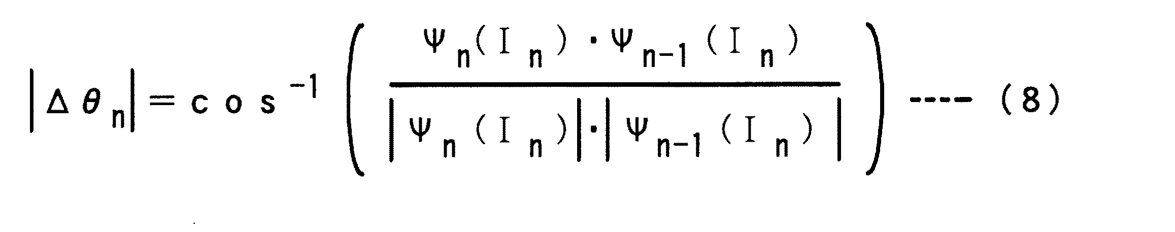
図3はドップラ周波数を示す図である。(A)は移動端末MSの進行方向に対し同一方向のパスから電波を受けた場合、(B)は移動端末MSの進行方向に対し垂直方向から電波を受けた場合を示している。 FIG. 3 is a diagram showing the Doppler frequency. (A) shows a case where radio waves are received from a path in the same direction as the traveling direction of the mobile terminal MS, and (B) shows a case where radio waves are received from a direction perpendicular to the traveling direction of the mobile terminal MS.
マルチパス環境では、電波はほぼ全方位から到来するとみなすことができ、到来角度分布は360°としてよい。したがって、(A)のように、移動端末MSの進行方向と同一方向のパスから電波を受ければ、θ=0、πとなり、式(1)より、ドップラ周波数の絶対値|fd|は最大となる。これを最大ドップラ周波数と呼び、最大ドップラ周波数fd,maxは次式のようになる。 In a multipath environment, radio waves can be regarded as coming from almost all directions, and the arrival angle distribution may be 360 °. Therefore, as shown in (A), if a radio wave is received from a path in the same direction as the traveling direction of the mobile terminal MS, θ = 0 and π, and the absolute value | fd | Become. This is called the maximum Doppler frequency, and the maximum Doppler frequency f d, max is expressed by the following equation.
また、(B)のように、移動端末MSの進行方向に対し垂直方向から電波を受ける場合は、進行方向に対する見かけ上の電波の波長は生成されないので、移動端末MSが移動していないのと同じことになり、ドップラシフトの影響は受けない(θ=π/2、3π/2となり、fd=0)。 In addition, as shown in (B), when receiving radio waves from a direction perpendicular to the traveling direction of the mobile terminal MS, the apparent wavelength of the radio waves with respect to the traveling direction is not generated, and therefore the mobile terminal MS is not moving. This is the same and is not affected by the Doppler shift (θ = π / 2, 3π / 2, and fd = 0).
図4はドップラ周波数の遷移を示す模式図である。グラフの横軸は時間、縦軸は移動端末MSの電波受信レベルであり、移動端末MSの移動に伴うフェージング変動(フェージング波のモデル図)を表している。図に示す移動端末MSに対して、マルチパスA方向からの到来波はfc+fd、マルチパスB方向からの到来波はfcとなる(fc:キャリア周波数、fd:ドップラ周波数)。マルチパスAの位相θAは、θA=2π(fc+fd)・t、マルチパスBの位相θBは、θB=2π・fc・tであり、マルチパスの位相差(Δθ=θA−θB=2π・fd・t)は、移動端末MSの移動と共に変化する。 FIG. 4 is a schematic diagram showing the transition of the Doppler frequency. The horizontal axis of the graph is time, and the vertical axis is the radio wave reception level of the mobile terminal MS, which represents fading fluctuations (fading wave model diagram) accompanying the movement of the mobile terminal MS. For the mobile terminal MS shown in the figure, the incoming wave from the multipath A direction is fc + fd, and the incoming wave from the multipath B direction is fc (fc: carrier frequency, fd: Doppler frequency). The phase θ A of the multipath A is θ A = 2π (fc + fd) · t, the phase θ B of the multipath B is θ B = 2π · fc · t, and the multipath phase difference (Δθ = θ A − θ B = 2π · fd · t) changes as the mobile terminal MS moves.
ここで、図3の説明からわかるように、マルチパスA、Bの到来波が逆位相になったときがグラフのt1の状態であり、同位相になったときがt2の状態になる。なお、図に示す時間0〜t2までの間隔はドップラ周波数の周期となる(なお、ドップラ周波数はフェージング周波数、ドップラ周波数の周期はフェージング周期とも呼ばれる)。
Here, as can be seen from the description of FIG. 3, the time when the incoming waves of the multipaths A and B are in opposite phases is the state of t1 in the graph, and the state when they are in phase is the state of t2. The interval from
このようにして生じるドップラシフトによるフェージング変動は、下りリンク(移動局での受信)だけでなく、上りリンク(基地局での受信)においても同様に発生する。特に、フェージングによる受信電界強度の落ち込み(例えば、図4の時間t1の受信レベル)は、無線通信における情報伝送誤りを増大する原因となる。 The fading fluctuation caused by the Doppler shift generated in this way occurs not only in the downlink (reception at the mobile station) but also in the uplink (reception at the base station). In particular, a drop in received electric field strength due to fading (for example, a reception level at time t1 in FIG. 4) causes an increase in information transmission errors in wireless communication.
したがって、ドップラ周波数を精度よく推定することができれば、フェージング周期に応じて、通信方式を選択したり、受信アルゴリズムを最適化したりするなどの工夫を行うことにより、無線通信特性を大幅に向上させることが期待できる。 Therefore, if the Doppler frequency can be estimated accurately, wireless communication characteristics can be greatly improved by selecting communication methods or optimizing reception algorithms according to the fading period. Can be expected.
例えば、ドップラ周波数が低い場合(フェージング変動の影響が小さく無線環境が良い場合)には、16QAM(Quadrature Amplitude Modulation)や64QAMなどの多値変調を用いて伝送レートを上げて、できるだけ多くの情報量を伝送し、逆にドップラ周波数が高い場合(フェージング変動の影響が大きく無線環境が悪い場合)には、フェージング変動の影響を受けにくいBPSK(Binary Phase Shift Keying)やQPSK(Quadrature Phase Shift Keying)などを用いて伝送レートを下げて、少ない情報量を確実に伝送するといった、伝搬環境に応じて変調方式の切り替えを行う適応変調方式を採用することが考えられる。 For example, when the Doppler frequency is low (when the influence of fading fluctuation is small and the wireless environment is good), the transmission rate is increased using multi-level modulation such as 16QAM (Quadrature Amplitude Modulation) or 64QAM, and as much information as possible When the Doppler frequency is high (when the influence of fading fluctuation is large and the wireless environment is bad), BPSK (Binary Phase Shift Keying) and QPSK (Quadrature Phase Shift Keying) are not easily affected by the fading fluctuation. It is conceivable to adopt an adaptive modulation scheme that switches the modulation scheme in accordance with the propagation environment, such as reducing the transmission rate by using, to reliably transmit a small amount of information.
また、パイロットシンボルによるチャネル推定の結果にもとづき同期検波を行う場合でもドップラ周波数の推定精度は重要である。図5はチャネル推定の概要を示す図である。フェージング環境においては、受信信号は振幅の変動のみならず、位相も変動(回転)することになる。QPSKを例にして説明すると、実際に送信側が送信した信号(シンボル)が信号点S1の場合、フェージングによって位相がα回転し、受信側では信号点S2で受信したとする。この信号点S2の情報をそのまま復調すれば誤りになってしまう。 In addition, the Doppler frequency estimation accuracy is important even when synchronous detection is performed based on the result of channel estimation using pilot symbols. FIG. 5 is a diagram showing an outline of channel estimation. In a fading environment, the received signal not only varies in amplitude but also varies (rotates) in phase. To explain using QPSK as an example, when the signal (symbol) actually transmitted by the transmitting side is the signal point S1, it is assumed that the phase is rotated α by fading and the receiving side receives the signal at the signal point S2. If the information of the signal point S2 is demodulated as it is, an error occurs.
したがって、受信側では、現在のフェージングによって位相がどれぐらい回転したか(チャネル変動)を検出して、位相変動分を元に戻す必要がある(この例では、−αの位相補正を行う)。チャネル推定を行う際には、送信側はパイロットシンボルと呼ばれる基準信号を常に一定の位相で送信する(送信信号にパイロットシンボルは内挿される)。受信側でもパイロットシンボルの位相を既知としているので、受信側ではこのパイロットシンボルを検出して、現在のフェージングによる位相回転を推定し、位相補正を行って、チャネルを推定する。そして、チャネル推定の結果により同期検波を行えば、正確にデータを復調することができる。 Therefore, on the receiving side, it is necessary to detect how much the phase has been rotated by the current fading (channel fluctuation), and to restore the original phase fluctuation (in this example, -α phase correction is performed). When performing channel estimation, the transmission side always transmits a reference signal called a pilot symbol with a constant phase (the pilot symbol is interpolated in the transmission signal). Since the phase of the pilot symbol is also known on the receiving side, the pilot side is detected on the receiving side, the phase rotation due to the current fading is estimated, the phase is corrected, and the channel is estimated. If synchronous detection is performed based on the result of channel estimation, data can be accurately demodulated.
ただし、実際のチャネル推定では、1つのパイロットシンボルだけを見ているのではなく、ノイズの影響を考えて複数のパイロットシンボルを平均化してチャネル推定を行っている。この場合、ノイズの影響を低減することだけを考えれば、平均化する区間を長くとればよいことになるが、フェージング変動が大きい環境で平均化区間を長くとってしまうと、レベル変動の大きい他シンボルも含めて演算することになるために、誤りも大きくなってしまう。 However, in actual channel estimation, not only one pilot symbol is seen, but channel estimation is performed by averaging a plurality of pilot symbols in consideration of the influence of noise. In this case, if only the reduction of the influence of noise is considered, it is only necessary to lengthen the averaging period. However, if the averaging period is long in an environment where fading fluctuation is large, the level fluctuation is large. Since the calculation includes symbols, the error becomes large.
したがって、ドップラ周波数が低い場合には、チャネル推定の平均化区間を長くとることによりチャネル推定精度を高め、逆にドップラ周波数が高い場合には、フェージング変動によりチャネル推定精度が劣化するのを避けるために、平均化区間を短く設定する、というような方法を選択すれば、常に最適な受信特性を得ることができる。 Therefore, when the Doppler frequency is low, the channel estimation accuracy is increased by taking a longer channel estimation averaging period. Conversely, when the Doppler frequency is high, the channel estimation accuracy is prevented from deteriorating due to fading fluctuations. In addition, if a method of setting the averaging interval short is selected, it is possible to always obtain optimum reception characteristics.
次に従来のドップラ周波数推定技術として、ドップラ周波数のレベル変動のピッチを測定する方法(従来技術1と呼ぶ)とその問題点について説明する。図6はドップラ周波数のレベル変動のピッチ測定を示す図である。従来技術1では、受信信号の振幅に対し、基準値を設けて、受信電界強度が基準値より高くなったり低くなったりする回数(Level Crossing Rate)をカウントすることにより、フェージング周波数を推定するものである。
Next, as a conventional Doppler frequency estimation technique, a method of measuring the level fluctuation pitch of the Doppler frequency (referred to as Prior Art 1) and its problems will be described. FIG. 6 is a diagram showing the pitch measurement of the level fluctuation of the Doppler frequency. In
しかし、従来技術1では、受信電界強度の変化を連続的に測定するため、受信信号レベルを求めるための平均区間を短く設定する必要があり、高いフェージング周波数を精度よく測定することが難しい。また、マルチパスフェージングの変動は、マルチパス数が多くなるほど複雑になるため、Level Crossing Rateから実際のフェージング速度に変換することは容易ではない。さらに、Level Crossing Rateの基準値によっても推定結果が大きく変わるため、シャドウイング(Shadowing)などにより平均受信レベルが大きく変化するシステムにおいて、安定した精度で推定結果を得るのは難しいといった問題があった。
However, in the
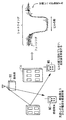
図7はシャドウイングによる受信レベル変化を示す図である。シャドウイングとは、長区間変動であって(フェージングは短区間変動である)、伝搬路の見通しが障害物によって、例えば、数秒〜数十秒遮られて受信品質が劣化する現象のことである。 FIG. 7 is a diagram showing a change in reception level due to shadowing. Shadowing is a long-term fluctuation (fading is a short-term fluctuation), and is a phenomenon in which the line of sight is obstructed by an obstacle, for example, for several seconds to several tens of seconds, and reception quality deteriorates. .
図に示すように、移動端末MSがビルの影に隠れた場合、見通しのよかった基地局BSからの電波を直接受信することはできなくなって、反射波を受信するようになり受信レベルが低下する。このような環境下では、基地局BSと移動端末MSの見通しが良いときの受信レベルと、シャドウイングが発生しているときの受信レベルとでは大きく変わることになる。したがって、従来技術1のように1つの基準値でピッチを測定すると、ドップラ周波数の推定結果は大きく変動してしまい高精度に推定できないことがわかる。
As shown in the figure, when the mobile terminal MS is hidden in the shadow of the building, it is impossible to directly receive radio waves from the base station BS with good visibility, and it receives reflected waves and the reception level decreases. . Under such circumstances, the reception level when the line of sight of the base station BS and the mobile terminal MS is good and the reception level when shadowing is occurring vary greatly. Therefore, when the pitch is measured with one reference value as in the
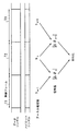
次に従来のドップラ周波数推定技術として、一定間隔のチャネル推定値の位相差を測定する方法(従来技術2と呼ぶ)とその問題点について説明する。図8はチャネル推定値の位相差測定の概念を示す図である。従来技術2では、無線フレーム毎に求めたチャネル推定値の位相差の絶対値を、複数フレームにわたって平均化することでドップラ周波数を推定する。
Next, as a conventional Doppler frequency estimation technique, a method of measuring a phase difference between channel estimation values at regular intervals (referred to as Conventional technique 2) and its problems will be described. FIG. 8 is a diagram illustrating the concept of phase difference measurement of channel estimation values. In the
例えば図では、無線フレームT1内の複数のパイロットシンボルを平均化してチャネル推定値hn-1を求め、無線フレームT2内の複数のパイロットシンボルを平均化してチャネル推定値hnを求め、無線フレームT3内の複数のパイロットシンボルを平均化してチャネル推定値hn+1を求めている(すなわち、各フレームにおける位相変動を求めている)。そして、チャネル推定値の位相差を以下の式で算出する。 For example, in the figure, a plurality of pilot symbols in the radio frame T1 are averaged to obtain a channel estimation value h n-1, and a plurality of pilot symbols in the radio frame T2 are averaged to obtain a channel estimation value h n. A plurality of pilot symbols in T3 are averaged to obtain a channel estimation value h n + 1 (that is, a phase variation in each frame is obtained). Then, the phase difference between the channel estimation values is calculated using the following equation.
式(3)で求めたチャネル推定値の位相差Δθnには、フェージングによる位相変動分と、周波数オフセット(キャリアオフセット)による位相変化量とが含まれている。ここで、周波数オフセットについて説明すると、W−CDMAの場合、キャリア周波数は2GHzが用いられるが、基地局が生成する2GHzと移動端末が生成する2GHzとは正確に一致することはない。例えば、基地局では2.00001GHzであり、移動端末では1.9999GHzというように、送受信間では周波数に若干のずれ(周波数オフセット)を持っている。 The phase difference Δθn of the channel estimation values obtained by Expression (3) includes a phase variation due to fading and a phase change amount due to a frequency offset (carrier offset). Here, the frequency offset will be described. In the case of W-CDMA, 2 GHz is used as the carrier frequency, but 2 GHz generated by the base station and 2 GHz generated by the mobile terminal do not exactly match. For example, the frequency is slightly different (frequency offset) between transmission and reception, such as 2.00001 GHz for a base station and 1.9999 GHz for a mobile terminal.
位相変動はフェージングだけでなく、この周波数オフセットによっても生じる。したがって、フェージングによって生じる位相変動がなかったとしても、キャリアの周波数オフセットによって位相変動が生じることになる。 Phase variation is caused not only by fading but also by this frequency offset. Therefore, even if there is no phase fluctuation caused by fading, the phase fluctuation occurs due to the carrier frequency offset.
ここで、式(1)からわかるように、フェージングによる位相変動の方向は様々であるが、周波数オフセットによる位相変動は一定方向のみ回転する。例えば、フェージングの位相変動の場合、+10°方向に2回転したら、次は−10度方向に3回転するというように、位相変動は一定方向には回転しない。また、周波数オフセットの位相変動の場合では、例えば、周波数オフセットが80Hzであったなら、80Hzの決まった速度で一定方向に回転することになる。 Here, as can be seen from Equation (1), the direction of phase fluctuation due to fading varies, but the phase fluctuation due to frequency offset rotates only in a certain direction. For example, in the case of fading phase fluctuation, after two rotations in the + 10 ° direction, the next three rotations in the −10 degree direction do not rotate the phase fluctuation in a fixed direction. Further, in the case of the phase variation of the frequency offset, for example, if the frequency offset is 80 Hz, it rotates in a constant direction at a fixed speed of 80 Hz.
このため、Δθnをそのまま平均化(ベクトル成分の平均化)してしまうと、フェージングによる位相変動成分が消えてしまい、周波数オフセット成分のみが残ることになる。なぜなら、フェージングによる位相変動では、上述のように+10°方向に2回転したら、−10°方向に3回転、…といったことの繰り返しであるので、平均するとゼロに近づくからであり、また、周波数オフセットは単位時間当たり、例えば、+10°、+10°、…といったことの繰り返しであるので、平均しても周波数オフセットの成分は残るからである。したがって、フェージングによる位相変動量を推定するには、式(3)のΔθnの絶対値をとって平均化(スカラーの平均化)する必要がある。 For this reason, if Δθn is averaged as it is (vector component averaging), the phase fluctuation component due to fading disappears and only the frequency offset component remains. This is because, in phase fluctuation due to fading, if it is rotated twice in the + 10 ° direction as described above, it is repeated three times in the −10 ° direction, and so on. This is because, for example, + 10 °, + 10 °,... Is repeated per unit time, so that a frequency offset component remains even if averaged. Therefore, in order to estimate the amount of phase fluctuation due to fading, it is necessary to take the absolute value of Δθn in equation (3) and average it (scalar averaging).
または、式(3)の他に、次式に示すようにチャネル推定値の内積から位相差の絶対値を直接計算することができるため、この値を平均化することにより、以下の式(4)のようにして、ドップラ周波数の推定を行うこともできる。 Alternatively, in addition to the equation (3), the absolute value of the phase difference can be directly calculated from the inner product of the channel estimation values as shown in the following equation. By averaging this value, the following equation (4) ), The Doppler frequency can be estimated.
そして、このようにして求めた位相差の絶対値を平均化し、その平均値をフレーム間隔時間で割ると毎秒何度で位相が回っているか、ということが推定できる。今、チャネル推定を行うフレーム間隔時間をTとすると、ドップラ周波数は、以下の式(5)で求められる。なお、Nは平均化フレーム数を表す。 Then, by averaging the absolute values of the phase differences obtained in this way and dividing the average value by the frame interval time, it can be estimated how many times the phase is rotated per second. Now, assuming that the frame interval time for channel estimation is T, the Doppler frequency is obtained by the following equation (5). N represents the number of averaged frames.
しかし、従来技術2では、位相差の絶対値を平均化するため、雑音成分はキャンセルされず、累積して平均化されてしまう(雑音もフェージングの位相変動と同様に一定方向には回転しない。よって、ベクトル成分で平均化すれば雑音成分は低減する方向に向かうが、スカラー平均を行っているので、雑音成分は累積してしまう)。したがって、ドップラ周波数の推定結果は、雑音成分の影響を大きく受け、雑音レベルが高いほど、推定結果が実際のドップラ周波数よりも大きな値となってしまうといった問題があった。
However, in the
現在の無線通信システムでは、ダイバーシチ受信や誤り訂正技術を用いて、S/Nが低い領域においても良好な通信特性を実現している。また、送信電力制御を併用することにより、少ない送信電力で所要の通信品質を確保し、端末の通話時間を長くするなどの工夫がなされている。 In the current wireless communication system, good communication characteristics are realized even in an area where the S / N is low by using diversity reception and error correction technology. Further, by using the transmission power control together, a device has been devised such as ensuring a required communication quality with a small transmission power and extending the call time of the terminal.
このように、受信信号のS/Nは一般的に高くなく、このような無線環境の中でドップラ周波数を高精度に推定することは困難となっている。上記のような問題点を解決し、S/Nが低い領域においても、ドップラ周波数を高精度に推定して無線通信特性の向上を図った通信装置を実現するものである。 Thus, the S / N of the received signal is generally not high, and it is difficult to estimate the Doppler frequency with high accuracy in such a wireless environment . To solve the problems described above SL, in S / N is low region, and realizes a communication device with improved wireless communication properties by estimating the Doppler frequency with high accuracy.
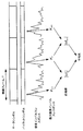
次に通信装置10の動作(ドップラ周波数推定方法)について詳しく説明する。まず、第1の実施の形態の動作について説明する。図9はドップラ周波数推定の概念を示す図である。図に示すように、無線フレームT毎の受信信号を用いて、複素インパルスレスポンスを求め、その最大値である最大複素インパルスレスポンスを検出する。そして、無線フレームT毎の最大複素インパルスレスポンスの位相差の絶対値を計算し、複数の無線フレームに渡り平均化することにより、ドップラ周波数を推定する。
Detail the operation of the
複素インパルスレスポンスは、パイロットシンボル(または基地局から常時送信される同期チャネルを用いてもよい)等の既知の信号を用いて、そのレプリカを通信装置10内で生成し、受信信号とレプリカとの相関値を計算することにより求めることができる。
The complex impulse response is generated using a known signal such as a pilot symbol (or a synchronization channel that is always transmitted from the base station) or the like in the
図10は複素インパルスレスポンス測定部11の動作概要を示す図である。複素インパルスレスポンス測定部11では、受信信号とパイロットシンボル系列(パイロットシンボルのレプリカ)との相関値を、乗算器11−1〜11−8及び加算器11−9を用いて計算する。受信信号にはパイロットシンボルが内挿されているので、レプリカと一致した場合には、相関が最も高くなり、このときインパルスが立つことになる。したがって、最初に受信したマルチパスのパスに対してインパルスが立ち、次に受信したマルチパスのパスに対してインパルスが立つということが繰り返されて、遅延プロファイルが測定され、かつ複素インパルスレスポンスも測定することができる。
FIG. 10 is a diagram showing an outline of the operation of the complex impulse
次に複素インパルスレスポンスの定義式を示す。今、1つの無線フレームにおけるパイロットシンボルの信号系列(レプリカ)をSk(k=0〜K−1)とし、n番目のフレームのタイミングiにおける受信信号をRn(i)とすると、複素インパルスレスポンスΨn(i)は、次式で求められる(*は複素共役を示す)。 Next, the definition formula of the complex impulse response is shown. Now, assuming that the pilot symbol signal sequence (replica) in one radio frame is Sk (k = 0 to K−1) and the received signal at the timing i of the nth frame is Rn (i), the complex impulse response Ψn. (I) is obtained by the following equation (* indicates a complex conjugate).
ここで、i、kは、送受のサンプルタイミングであり、複素インパルスレスポンスの分解能は、サンプリングレートの逆数となる。一般の無線通信方式では、4倍から8倍のオーバーサンプルが用いられるため、インパルスレスポンス測定の分解能もシンボルレートの4倍から8倍となる。 Here, i and k are transmission / reception sample timings, and the resolution of the complex impulse response is the reciprocal of the sampling rate. In general wireless communication systems, oversampling of 4 to 8 times is used, so that the resolution of impulse response measurement is also 4 to 8 times the symbol rate.
次に最大複素インパルスレスポンスΨnの位相差の絶対値を次式により求める。 Next, the absolute value of the phase difference of the maximum complex impulse response Ψn is obtained by the following equation.
そして、上述した式(5)のように、Nフレームに渡り平均化し、ドップラ周波数を推定する。
一方、無線フレーム間で最大複素インパルスレスポンスのタイミングが頻繁に変動する場合は、式(7)で位相差を求めると、フェージングの推定精度が劣化する可能性がある。このような場合は、第2の実施の形態として、2つのフレーム間で同一タイミングにおける、最大複素インパルスレスポンスと複素インパルスレスポンスとの位相差を用いるようにする。この第2の実施の形態について図11、図12を用いて説明する。
Then, as in Equation (5) described above, the Doppler frequency is estimated by averaging over N frames.
On the other hand, if the timing of the maximum complex impulse response frequently fluctuates between radio frames, the estimation accuracy of fading may be deteriorated if the phase difference is obtained by Equation (7). In such a case , as the second embodiment, the phase difference between the maximum complex impulse response and the complex impulse response at the same timing between the two frames is used. The second embodiment will be described with reference to FIGS.
図11は最大複素インパルスレスポンスの変動を示す図である。無線フレームT1では、最大複素インパルスレスポンスΨ1が位置Pa1にあり、次の無線フレームT2では、最大複素インパルスレスポンスΨ2が位置Pa2にあるが、このように、最大複素インパルスレスポンスの位置が頻繁に変動するような場合、最大複素インパルスレスポンスΨ1、Ψ2のそれぞれの位相差Δθを算出すると、波形がずれたことによる変動分がΔθの中に含まれてしまい、推定精度が劣化するおそれがある。 FIG. 11 is a diagram showing fluctuations in the maximum complex impulse response. In the radio frame T1, the maximum complex impulse response Ψ1 is at the position Pa1, and in the next radio frame T2, the maximum complex impulse response Ψ2 is at the position Pa2. Thus, the position of the maximum complex impulse response frequently fluctuates. In such a case, if the phase difference Δθ of each of the maximum complex impulse responses ψ1 and ψ2 is calculated, the variation due to the waveform shift is included in Δθ, and the estimation accuracy may be degraded.
図12は2つのフレーム間における複素インパルスレスポンスの位相差を求める場合を説明するための図である。無線フレームT1では、最大複素インパルスレスポンスΨ1が位置Pa1にあり、次の無線フレームT2では、最大複素インパルスレスポンスΨ2が位置Pa2にあり、次の無線フレームT3では、最大複素インパルスレスポンスΨ3が位置Pa3にあるとする。 FIG. 12 is a diagram for explaining a case where the phase difference of the complex impulse response between two frames is obtained. In the radio frame T1, the maximum complex impulse response Ψ1 is at the position Pa1, in the next radio frame T2, the maximum complex impulse response Ψ2 is at the position Pa2, and in the next radio frame T3, the maximum complex impulse response Ψ3 is at the position Pa3. Suppose there is.
このような場合、無線フレームT1の最大複素インパルスレスポンスΨ1と、無線フレームT2の位置Pa1上の複素インパルスレスポンスΨ2aとの位相差を求める(すなわち、無線フレームT1の最大複素インパルスレスポンスと同一タイミングの無線フレームT2上の複素インパルスレスポンスとの位相差を求める)。そして、次は無線フレームT2の最大複素インパルスレスポンスΨ2と、無線フレームT3の位置Pa2上の複素インパルスレスポンスΨ3aとの位相差を求める(同様に、無線フレームT2の最大複素インパルスレスポンスと同一タイミングの無線フレームT3上の複素インパルスレスポンスとの位相差を求める)。 In such a case, the phase difference between the maximum complex impulse response Ψ1 of the radio frame T1 and the complex impulse response Ψ2a on the position Pa1 of the radio frame T2 is obtained (that is, the radio signal having the same timing as the maximum complex impulse response of the radio frame T1). The phase difference from the complex impulse response on the frame T2 is obtained). Next, the phase difference between the maximum complex impulse response ψ2 of the radio frame T2 and the complex impulse response ψ3a on the position Pa2 of the radio frame T3 is obtained (similarly, the radio wave having the same timing as the maximum complex impulse response of the radio frame T2). The phase difference from the complex impulse response on the frame T3 is obtained).
このように、フレーム(n−1)に対し、最大複素インパルスレスポンスが発生したタイミングt1を固定して、フレーム(n−1)の最大複素インパルスレスポンスと、同一タイミングt1によるフレームnの複素インパルスレスポンスと、の位相差の絶対値を求める。さらに、フレームnに対し、最大複素インパルスレスポンスが発生したタイミングt2を固定して、フレームnの最大複素インパルスレスポンスと、同一タイミングt2によるフレーム(n+1)の複素インパルスレスポンスと、の位相差の絶対値を求める…といったことを繰り返すことにより、波形ずれの変動分がΔθに与える影響を抑制することができ、推定精度の劣化を低減させることができる。 In this way, the timing t1 at which the maximum complex impulse response is generated is fixed with respect to the frame (n-1), the maximum complex impulse response of the frame (n-1), and the complex impulse response of the frame n at the same timing t1. The absolute value of the phase difference between and is obtained. Further, the timing t2 at which the maximum complex impulse response is generated is fixed with respect to the frame n, and the absolute value of the phase difference between the maximum complex impulse response of the frame n and the complex impulse response of the frame (n + 1) at the same timing t2. By repeating the above, it is possible to suppress the influence of the fluctuation amount of the waveform deviation on Δθ, and to reduce the deterioration of the estimation accuracy.
今、n番目のフレームにおける最大複素インパルスレスポンスのタイミングをInとすると、図12で示したような制御による位相差の絶対値は次式により求まる。 Now, assuming that the timing of the maximum complex impulse response in the nth frame is In, the absolute value of the phase difference by the control as shown in FIG.
そして、上述した式(5)を用いて、Nフレームに渡り平均化し、ドップラ周波数を推定する。
以上説明したように、最大複素インパルスレスポンス(S/Nの高いマルチパス)を利用してドップラ周波数を推定するため、常にS/Nが最大となる状態で高精度にドップラ周波数推定を行うことが可能になる。したがって、雑音成分の影響を最小にでき、また高い分解能で複素インパルスレスポンスを求めることにより、余分なマルチパス成分の影響を排除し短い平均区間で、ドップラ周波数を推定することが可能になる。
Then, the above equation (5) is used to average over N frames to estimate the Doppler frequency.
As described above, in order to estimate the Doppler frequency by using the maximum complex impulse response (S / N high multipath), always performing Doppler frequency estimation with high precision in a state where S / N is maximized Is possible. Therefore, the influence of the noise component can be minimized, and by obtaining the complex impulse response with high resolution, the influence of the extra multipath component can be eliminated and the Doppler frequency can be estimated in a short average interval.
次に通信装置10を適用したディジタル無線受信機について説明する。図13はディジタル無線受信機の構成を示す図である。ディジタル無線受信機100は、A/D部101〜復号部107で構成されるデータ再生部の他に、複素インパルスレスポンス測定部、位相差演算部、平均化演算部、ドップラ周波数推定部を含む。複素インパルスレスポンス測定部11は、パイロットシンボル生成部11aと相関算出部11bから構成され、位相差演算部12は、最大値検出部12a、遅延部12b、位相差検出部12cから構成される。
It explained digital radio receiver next to the application of the
A/D部101は、アンテナより受信したRF(Radio Frequency)信号を周波数変換し、直交検波によりIチャネルとQチャネルとのベースバンド信号に分ける。そして、それぞれの信号をA/D変換して、ディジタル信号へ変換する。
The A /
同期CH生成部102は、タイミング同期部103で、フレームタイミング(フレームの先頭位置を示すタイミング情報)の検出に用いる同期チャネルのレプリカを生成する。タイミング同期部103は、同期チャネルを用いて、A/D変換後のディジタル信号に含まれるフレームタイミングを検出する。
The synchronization
チャネル推定部104は、パイロットシンボルを用いて、チャネル情報を推定する。同期検波部105は、チャネル推定部104で求めたチャネル情報を用いて、受信信号からマルチパス伝搬路の影響を除去し、送信信号の状態に戻す検波処理を行う。
復調部106は、QPSKや16QAMなどの変調信号を元に戻し、データ系列へ復調する。復号部107は、畳込み符号化やターボ符号化などの誤り訂正符号化されたデータを復号化し、情報ビットを再生する。
The
パイロットシンボル生成部11aは、時間分解能の高い複素インパルスレスポンスを得るために、拡散後(CDMAの場合)やオーバーサンプル後のパイロットシンボルのレプリカを生成する。相関算出部11bは、パイロットシンボル系列と受信信号との相関演算を行い、時間分解能の高い複素インパルスレスポンスΨn(i)を生成する(なお、複素インパルスレスポンスは、時間分解能の高いチャネル情報であり、複素インパルスレスポンスの電力を平均化したものは、電力遅延プロファイルとなる)。
The
位相差演算部12に対し、第1の実施の形態の動作を行う場合について示すと、最大値検出部12aは、複素インパルスレスポンスの最大値(最大複素インパルスレスポンスΨn)を検出する。遅延部12bは、検出された最大複素インパルスレスポンスΨnを1フレーム遅延させる(最大複素インパルスレスポンスΨn−1)。
In the case where the operation of the first embodiment is performed for the phase difference calculation unit 12, the maximum
位相差検出部12cは、フレームnの最大複素インパルスレスポンスΨnと、フレーム(n−1)の最大複素インパルスレスポンスΨn−1とに対し、位相差の絶対値|Δθn|(=|∠Ψn−∠Ψn−1|)を計算する。
The phase
そして、平均化演算部13は、位相差の絶対値を複数フレームに渡り平均化して平均値情報を求める。ドップラ周波数推定部14は、平均値情報から、ドップラ周波数(Hz)に変換する。
The averaging calculator 13 averages the absolute value of the phase difference over a plurality of frames to obtain average value information. The Doppler
次に第3の実施の形態について説明する。上記の説明では、ドップラ周波数を推定する際に、第1の実施の形態では、“最大複素インパルスレスポンスの位相差の絶対値を複数フレームに渡り平均化すること(図9、10)”、第2の実施の形態では、“フレーム(n−1)の最大複素インパルスレスポンスが発生したタイミングを固定して、フレーム(n−1)の最大複素インパルスレスポンスと、同一タイミングによるフレームnの複素インパルスレスポンスと、の位相差の絶対値を求めること(図11、12)”について述べた。 A third embodiment will be described next. In the above description, when the Doppler frequency is estimated, in the first embodiment, “the absolute value of the phase difference of the maximum complex impulse response is averaged over a plurality of frames (FIGS. 9 and 10)”, In the second embodiment, “the timing at which the maximum complex impulse response of frame (n−1) is generated is fixed, the maximum complex impulse response of frame (n−1), and the complex impulse response of frame n at the same timing. And obtaining the absolute value of the phase difference between them (FIGS. 11 and 12) ”.
以降では第3の実施の形態として、“複数フレームに渡って同一タイミングによる複素インパルスレスポンスの位相差の絶対値を求める”ことの内容について説明する。
図13のディジタル無線受信機100の位相差演算部12において、複素インパルスレスポンスの位相差演算を行う際に、最大複素インパルスレスポンスが発生するタイミングを更新するとき、平均化演算部13では、各無線フレームでフェージング状態が良好であるパスの位相変化量(|Δθn|(=|∠Ψn−∠Ψn−1|)のみが平均化される。
Hereinafter, as the third embodiment, the content of “determining the absolute value of the phase difference of the complex impulse response at the same timing over a plurality of frames” will be described.
When the phase difference calculation unit 12 of the digital radio receiver 100 of FIG. 13 performs the phase difference calculation of the complex impulse response, when updating the timing at which the maximum complex impulse response occurs, the averaging calculation unit 13 Only the phase change amount (| Δθn | (= | ∠Ψn−∠Ψn-1 |)) of the path in which the fading state is good in the frame is averaged.
一般的に、フェージング状態が良好な部分の位相変化量は、フェージングの落ち込み部分の位相変化量よりも小さいため、上記のようにフェージング状態が良好な部分のみの平均化を行うと、実際よりも低いドップラ周波数が推定されてしまう可能性がある(すなわち、フェージングの落ち込み部分の位相変化量も考慮した平均化を行わないと、フェージングの落ち込み具合によっては、実際はドップラ周波数が高くて、フェージング変動の影響が大きい無線環境であっても、実際のドップラ周波数値よりも低いドップラ周波数が推定される可能性がある)。 In general, the amount of phase change in the fading state is smaller than that in the fading drop portion. A low Doppler frequency may be estimated (i.e., if averaging is not performed in consideration of the amount of phase change in the fading drop, depending on the fading drop, the Doppler frequency is actually high, and fading fluctuation Even in a wireless environment with a large influence, a Doppler frequency lower than the actual Doppler frequency value may be estimated).
したがって、第3の実施の形態では、複数の無線フレームに渡って位相変化量を平均化する場合、まず、位相差演算に用いる最大複素インパルスレスポンスを検出する。そして、このときの検出タイミングを固定し、このタイミングによる複数の他無線フレームの複素インパルスレスポンスを抽出して、抽出した複素インパルスレスポンス間の位相差の絶対値を求めるようにする。 Therefore, in the third embodiment, when averaging the amount of phase change over a plurality of radio frames, first, the maximum complex impulse response used for the phase difference calculation is detected. Then, the detection timing at this time is fixed, the complex impulse responses of a plurality of other radio frames at this timing are extracted, and the absolute value of the phase difference between the extracted complex impulse responses is obtained.
このようにすれば、フェージングの落ち込み部分の位相変化量も平均化できるため(フェージングが良好な部分に該当する最大複素インパルスレスポンスだけを用いた平均化処理だけでなく、フェージングの落ち込み部分を含む、最大複素インパルスレスポンス以外の複素インパルスレスポンスも用いた平均化処理も行うということ)、ドップラ周波数の推定精度を向上させることが可能になる。 In this way, since the phase change amount of the fading drop portion can be averaged (including not only the averaging process using only the maximum complex impulse response corresponding to the fading good portion, but also the fading drop portion, An averaging process using a complex impulse response other than the maximum complex impulse response is also performed), and the Doppler frequency estimation accuracy can be improved.
図14は同一タイミングにおける複素インパルスレスポンスの位相差を求める場合を説明するための図である。無線フレームT1で、最大複素インパルスレスポンスΨ1が位置Pb1で検出されたとする。次に無線フレームT2に対しては、位置Pb1のタイミングでの複素インパルスレスポンスΨ2bを抽出する。無線フレームT3に対しても、位置Pb1のタイミングでの複素インパルスレスポンスΨ3bを抽出する。次フレームに対しても同様なことが行われる。 FIG. 14 is a diagram for explaining a case where the phase difference of the complex impulse response at the same timing is obtained. It is assumed that the maximum complex impulse response Ψ1 is detected at the position Pb1 in the radio frame T1. Next, for the radio frame T2, the complex impulse response Ψ2b at the timing of the position Pb1 is extracted. Also for the radio frame T3, the complex impulse response Ψ3b at the timing of the position Pb1 is extracted. The same is done for the next frame.
そして、最大複素インパルスレスポンスΨ1と複素インパルスレスポンスΨ2bとの位相差の絶対値を求め、複素インパルスレスポンスΨ2bと複素インパルスレスポンスΨ3bとの位相差の絶対値を求める…といったことを平均化区間内のフレームに対して繰り返し、これらの位相差の絶対値の平均を求めることにより、平均値情報が求められ、平均値情報からドップラ周波数が推定されることになる。 Then, the absolute value of the phase difference between the maximum complex impulse response Ψ1 and the complex impulse response Ψ2b is obtained, the absolute value of the phase difference between the complex impulse response Ψ2b and the complex impulse response Ψ3b is obtained, and so on. The average value information is obtained by repeatedly calculating the average of the absolute values of these phase differences, and the Doppler frequency is estimated from the average value information.
図15は第3の実施の形態を行う際の最大値検出部の構成を示す図である。最大値検出部12a−1は、電力化部121、タイマ122、ピーク検出部123、メモリ124、複素インパルスレスポンス抽出部125とから構成される。
FIG. 15 is a diagram showing a configuration of a maximum value detection unit when the third embodiment is performed. The maximum
電力化部121は、図13の複素インパルスレスポンス測定部11から送信された複素インパルスレスポンスを受信して電力値に変換する。タイマ122は、平均化区間(平均化演算部13で平均化演算を行う際に定められている平均化フレーム数)毎に、複素インパルスレスポンスの電力値を後段へ出力する。
The
ここで、フレーム番号がnで、タイミングiにおけるタイマ出力信号φn(i)は、複素インパルスレスポンスΨn(i)を用いて、式(9)で表される。 Here, the frame number is n, and the timer output signal φ n (i) at timing i is expressed by equation (9) using the complex impulse response Ψ n (i).
ピーク検出部123では、平均化演算部13における平均化区間毎に、φn(i)が最大となるタイミングi=maxを検出する。メモリ124は、検出されたタイミング情報を保持する。また、平均化区間毎にタイミング情報は更新される。
The
複素インパルスレスポンス抽出部125は、複素インパルスレスポンス測定部11から送信された複素インパルスレスポンスを受信して、時間調整のための遅延処理を施した後、メモリ124に保持されたタイミングに該当する複素インパルスレスポンスを抽出して、その後、図13に示した遅延部12b及び位相差検出部12cへ出力する。
The complex impulse
また、図15では最大値検出部12a−1の動作が理解しやすいように、平均化区間内の各フレーム(フレームF1〜F4)における複素インパルスレスポンス(の電力)を示して動作を表している。ここでは、フレームF1で最大複素インパルスレスポンスa1が検出されたとすると、このときの検出タイミングt0がメモリ124に記憶される。
Further, in FIG. 15, the complex impulse response (power) in each frame (frames F1 to F4) in the averaging interval is shown to represent the operation so that the operation of the maximum
そして、複素インパルスレスポンス抽出部125では、フレームF1では検出タイミングt0の最大複素インパルスレスポンスa1を抽出し、フレームF2〜F4に対しては、検出タイミングt0のときの複素インパルスレスポンスを抽出することになる(その後、最大値検出部12a−1を出力した、これらの複素インパルスレスポンスは、遅延部12b、位相差検出部12cへ送られ、位相差の絶対値が計算される)。
The complex impulse
次に第3の実施の形態の変形例について説明する。上記では、平均化区間内の複数フレームに対して、最大複素インパルスレスポンスを検出し、最大複素インパルスレスポンスを検出した際のタイミングで、他フレームの複素インパルスレスポンスを抽出し、これらの位相差を求めたが、変形例の場合は、平均化区間内の各フレームの複素インパルスレスポンスの平均電力を算出して、平均電力が最大となるタイミングを検出し、検出した同一タイミングによる複数の他フレームの複素インパルスレスポンスを抽出して、抽出した複素インパルスレスポンスの位相差を求めるようにする。このような制御を行っても同様の効果を得ることができる。 Next, a modification of the third embodiment will be described. In the above, the maximum complex impulse response is detected for multiple frames in the averaging interval, and the complex impulse response of other frames is extracted at the timing when the maximum complex impulse response is detected, and the phase difference between these is obtained. However, in the case of the modified example, the average power of the complex impulse response of each frame in the averaging interval is calculated, the timing at which the average power becomes maximum is detected, and the complex of multiple other frames at the detected same timing is detected. The impulse response is extracted, and the phase difference of the extracted complex impulse response is obtained. Even if such control is performed, the same effect can be obtained.
図16は第3の実施の形態の変形例の動作を行う際の最大値検出部の構成を示す図である。最大値検出部12a−2は、電力化部126、平均化部127、ピーク検出部128、メモリ129、複素インパルスレスポンス抽出部130とから構成される。
FIG. 16 is a diagram illustrating a configuration of a maximum value detection unit when performing the operation of the modification of the third embodiment. The maximum
電力化部126は、図13の複素インパルスレスポンス測定部11から送信された複素インパルスレスポンスを受信して電力値に変換する。平均化部127は、平均化演算部13における平均化区間で、複素インパルスレスポンスの電力値を平均化して出力する。
The
ここで、平均化フレーム数をM、フレーム番号をnとし、タイミングiにおける平均化出力信号φ(i)は、複素インパルスレスポンスΨn(i)を用いて,式(10)で表される。 Here, the average number of frames is M, the frame number is n, and the averaged output signal φ (i) at the timing i is expressed by Equation (10) using the complex impulse response Ψ n (i).
例えば、式(10)は、M=4とすれば、φ(i)=[{Ψn(i)}2+{Ψn-1(i)}2+{Ψn-2(i)}2+{Ψn-3(i)}2]/4となり、フレーム番号がn〜(n−3)の4つのフレームに対して、各フレームのタイミングiにおける複素インパルスレスポンスの電力値の平均値を表している。 For example, in Equation (10), if M = 4, φ (i) = [{Ψ n (i)} 2 + {Ψ n−1 (i)} 2 + {Ψ n−2 (i)} 2 + {Ψ n−3 (i)} 2 ] / 4, and the average value of the power value of the complex impulse response at the timing i of each frame with respect to four frames with frame numbers n to (n−3) Represents.
ピーク検出部128は、平均化演算部13における平均化フレーム数毎に、φ(i)が最大となるタイミングi=maxを検出する。メモリ129は、検出されたタイミング情報を保持する。また、平均化区間毎にタイミング情報は更新される。
The
複素インパルスレスポンス抽出部130は、複素インパルスレスポンス測定部11から送信された複素インパルスレスポンスを受信して、時間調整のための遅延処理を施した後、メモリ129に保持されたタイミングに該当する複素インパルスレスポンスを抽出して、図13に示した遅延部12b及び位相差検出部12cへ出力する。
The complex impulse
図17は図16の最大値検出部12a−2の動作を説明するための図である。平均化区間内の各フレーム(フレームF1〜F4)において、1〜kのタイミングの複素インパルスレスポンス(の電力)を示している。このような複素インパルスレスポンスに、式(10)を用いて、平均化部127において各タイミングにおける平均化出力信号φ(i)を求めると、図に示すような算出式となる。
FIG. 17 is a diagram for explaining the operation of the
そして、ピーク検出部128では、φ(1)〜φ(k)の最大値を求めるが、ここではφ(2)が最大であったとする。すると、メモリ129は、i=2を記憶し、複素インパルスレスポンス抽出部130は、フレームF1〜F4のタイミングiが2のときの複素インパルスレスポンスΨ1(2)、Ψ2(2)、Ψ3(2)、Ψ4(2)を出力することになる。
Then, the
次に図13で上述したディジタル無線受信機100の変形例について説明する。Δθnにはフェージングによる位相変動及び周波数オフセットによる位相変動が含まれるが、周波数オフセットによる位相変動量が、フェージングによる位相変動量に対して同程度かまたは大きい場合は、周波数オフセットの影響が大きく現れてしまう。 Next, a modified example of the digital radio receiver 100 described above with reference to FIG. 13 will be described. Δθn includes phase fluctuation due to fading and phase fluctuation due to frequency offset. If the phase fluctuation due to frequency offset is the same or larger than the phase fluctuation due to fading, the effect of frequency offset appears to be large. End up.
このため、変形例では、AFC(Automatic Frequency Control:自動周波数制御)により、周波数オフセットをあらかじめ低減しておき、その上でドップラ周波数の推定を行うようにする。 Therefore, in the variable Katachirei, AFC: by (Automatic Frequency Control Automatic Frequency Control), previously reduced frequency offset, so as to estimate the Doppler frequency thereon.
図18は変形例であるディジタル無線受信機の構成を示す図である。なお、図13と同じ構成要素には同じ符号を付けてその説明は省略し、異なる構成要素を中心に説明する。ディジタル無線受信機100−1は、A/D部101〜復号部107で構成されるデータ再生部の他に、複素インパルスレスポンス測定部、位相差演算部、第1の平均化演算部、第2の平均化演算部、ドップラ周波数推定部、周波数オフセット推定部、D/A部、AFC部を含む。
FIG. 18 is a diagram showing a configuration of a digital radio receiver as a modification. Note that the same components as those in FIG. 13 are denoted by the same reference numerals and description thereof is omitted, and different components will be mainly described. Digital radio receiver 100-1, in addition to the configured data reproducing unit in the A /
複素インパルスレスポンス測定部11は、パイロットシンボル生成部11aと相関算出部11bから構成され、位相差演算部12−1は、最大値検出部12a、遅延部12b、位相差検出部12c−1から構成される。
The complex impulse
位相差演算部12−1内の位相差検出部12c−1は、1フレーム離れた最大複素インパルスレスポンスの位相差Δθnと、位相差の絶対値|Δθn|とを計算する。
第1の平均化演算部13aは、位相差の絶対値を複数フレームに渡り平均化して第1の平均値情報を求める。第2の平均化演算部13bは、位相差を複数フレームに渡り平均化して第2の平均値情報を求める。
The
The first averaging calculator 13a averages the absolute value of the phase difference over a plurality of frames to obtain first average value information. The second averaging calculator 13b averages the phase difference over a plurality of frames to obtain second average value information.
ドップラ周波数推定部14は、第1の平均値情報から、ドップラ周波数(Hz)に変換する。周波数オフセット推定部15は、第2の平均値情報から、周波数オフセット(Hz)に変換する。
The Doppler
D/A部16は、推定された周波数オフセット量をアナログ情報に変換する。AFC部17は、D/A部16からの周波数オフセット量にもとづき、受信信号から周波数オフセットの影響を除去し、除去した信号をA/D部101へ送信する。
The D /
次に通信装置10をOFDM(Orthogonal Frequency Division Multiplexing:直交周波数分割多重)受信装置に適用した場合について説明する。OFDMは、伝送帯域内に多数の直交する副搬送波(サブキャリア)を設け、それぞれのサブキャリアの振幅及び位相にデータを割り当て、PSKやQAMによりディジタル変調する方式である。
OFDM The
このOFDMは、多数のサブキャリアで伝送帯域を分割するもので、サブキャリア1波あたりの帯域を狭くすることで、それぞれのサブキャリアのシンボル長を長くし、またガードインターバルの付加や、周波数軸上及び時間軸上でのインタリーブ制御を行うことで、マルチパスによるシンボル間干渉(ISI:Inter Symbol Interference)の影響を除くことができる。 In this OFDM, the transmission band is divided by a large number of subcarriers. By narrowing the band per subcarrier, the symbol length of each subcarrier is increased, the guard interval is added, and the frequency axis is increased. By performing interleave control on the top and the time axis, it is possible to eliminate the influence of inter-symbol interference (ISI: Inter Symbol Interference) due to multipath.
さらに、同時にすべてのサブキャリアを同期変調させて周波数直交関係を保つことによって、サブキャリアの間隔を最少に設定できるため、周波数利用効率をあげることができる。 Furthermore, by simultaneously modulating all the subcarriers and maintaining the frequency orthogonal relationship, the interval between the subcarriers can be set to the minimum, so that the frequency utilization efficiency can be increased.
このような特徴を持つOFDMは、マルチパス妨害の影響を強く受ける地上波ディジタル放送に適用することが広く検討されており、例えば、ISDB−Tといった規格が提案され、実用化に向けて試験放送が実施されている。 OFDM having such characteristics has been widely studied to be applied to terrestrial digital broadcasting that is strongly affected by multipath interference. For example, a standard such as ISDB-T has been proposed, and test broadcasting is being put into practical use. Has been implemented.
OFDM受信装置では、各サブキャリアに多重されたパイロットシンボルを用いて、サブキャリア毎のチャネル推定値hn,mを求める(nはフレームをmはサブキャリア番号を表す)。データチャネルは、これらのチャネル推定値を用いて、サブキャリア毎に同期検波され、データ復調および誤り訂正復号される。 In the OFDM receiver, a channel estimation value h n, m is obtained for each subcarrier using pilot symbols multiplexed on each subcarrier (n represents a frame and m represents a subcarrier number). The data channel is synchronously detected for each subcarrier using these channel estimation values, and data demodulation and error correction decoding are performed.
一方、OFDM受信装置に対する適用については、チャネル推定値hn,mを逆フーリエ変換することにより、受信信号の複素インパルスレスポンスを求める。そして、フレームタイミング毎に、最大となる複素インパルスレスポンスを検出し、フレーム間の位相差の絶対値を求め、複数フレームに渡り平均化し、ドップラ周波数の推定結果を得るようにする。 On the other hand, the applied against the OFDM receiver, the channel estimation value h n, by performing inverse Fourier transform on m, determine the complex impulse response of the received signal. Then, for each frame timing, the maximum complex impulse response is detected, the absolute value of the phase difference between frames is obtained, averaged over a plurality of frames, and the Doppler frequency estimation result is obtained.
図19はOFDM受信装置の構成を示す図である。OFDM受信装置200は、A/D部201〜復号部207で構成されるデータ再生部の他に、複素インパルスレスポンス測定部、位相差演算部、平均化演算部、ドップラ周波数推定部を含む。複素インパルスレスポンス測定部21は、パイロットシンボル生成部21a、チャネル推定部21b、IFFT(Inverse Fast Fourier Transform)部21cから構成され、位相差演算部22は、最大値検出部22a、遅延部22b、位相差検出部22cから構成される。
FIG. 19 is a diagram illustrating a configuration of an OFDM receiver. OFDM receiving apparatus 200, in addition to the configured data reproducing unit in the A / D unit 201 to
A/D部201は、アンテナより受信したRF信号を周波数変換し、直交検波によりIチャネルとQチャネルとのベースバンド信号に分ける。そして、それぞれの信号をA/D変換して、ディジタル信号へ変換する。 The A / D unit 201 performs frequency conversion on the RF signal received from the antenna, and divides it into baseband signals of I channel and Q channel by orthogonal detection. Each signal is A / D converted into a digital signal.
同期CH生成部202は、タイミング同期部203で、フレームタイミングの検出に用いる同期チャネルのレプリカを生成する。タイミング同期部203は、同期チャネルを用いて、A/D変換後のディジタル信号に含まれるフレームタイミングを検出する。
The synchronization
FFT(Fast Fourier Transform)部204は、フーリエ変換処理により、時間領域の広帯域信号を、周波数領域のサブキャリア毎の信号に分ける。同期検波部205は、チャネル推定部21bで求めたチャネル情報を用いて、受信信号からマルチパス伝搬路の影響を除去し、送信信号の状態に戻す検波処理を行う。
An FFT (Fast Fourier Transform)
復調部206は、変調信号を元に戻し、データ系列へ復調する。復号部207は、畳込み符号化やターボ符号化などの誤り訂正符号化されたデータを復号化し、情報ビットに再生する。
The
パイロットシンボル生成部21aは、パイロットシンボルを生成する。チャネル推定部21bは、パイロットシンボルを用いて、チャネル情報を推定する。IFFT部21cは、サブキャリア毎のチャネル推定値を逆フーリエ変換処理することにより、時間領域の複素インパルスレスポンスΨn(i)を計算する。
The pilot
最大値検出部22aは、複素インパルスレスポンスの最大値(最大複素インパルスレスポンスΨn)を検出する。遅延部22bは、検出した最大複素インパルスレスポンスΨnを1フレーム遅延させる(最大複素インパルスレスポンスΨn−1)。位相差検出部22cは、1フレーム離れた最大複素インパルスレスポンスの位相差の絶対値|Δθn|(=|∠Ψn−∠Ψn−1|)を計算する。
The
平均化演算部23は、位相差の絶対値を複数フレームに渡り平均化して平均値情報を求める。ドップラ周波数推定部14は、平均値情報から、ドップラ周波数(Hz)に変換する。なお、周波数オフセットを除去した後にドップラ周波数を推定する変形例をOFDM受信装置に適用した場合の説明は省略する。
The averaging
また、図18、19の構成を組み合わせれば、AFC付きのOFDM装置を容易に構成することができる。
また、いずれの実施の形態においても、複素インパルスレスポンスが最大となるタイミングが複数存在した場合や、(平均)振幅の大きい複素インパルスレスポンスのタイミングが複数存在した場合は、それぞれのタイミングにおけるフレーム間の位相差の絶対値を求め、それらの結果を平均する方法により、ドップラ周波数を推定することができる。
Further, by combining the configurations of FIGS. 18 and 19, an OFDM device with AFC can be easily configured.
In any of the embodiments, when there are a plurality of timings at which the complex impulse response is maximized, or when there are a plurality of timings of complex impulse responses with a large (average) amplitude, between the frames at each timing. The Doppler frequency can be estimated by a method of obtaining the absolute value of the phase difference and averaging the results.
以上説明したように、S/Nの高いマルチパスを選択して用いることにより、受信信号のS/Nが低い領域においても、精度よくドップラ周波数を推定することが可能になる。また、OFDMに適用することにより、精度よくドップラ周波数を推定することができ、地上波放送の伝送品質の向上を図ることが可能になる。 As described above, by selecting and using a multipath having a high S / N, the Doppler frequency can be accurately estimated even in a region where the S / N of the received signal is low. Further, by applied to OFDM, it is possible to estimate accurately the Doppler frequency, it is possible to improve the transmission quality of the terrestrial broadcasting.
(付記1) 無線通信を行う通信装置において、
無線フレーム周期毎に、伝搬路の複素時間応答信号を測定する複素時間応答信号測定部と、
候補となる複素時間応答信号の位相差の絶対値を求める位相差演算部と、
位相差の絶対値を、複数の無線フレームに渡り平均化して平均値を求める平均化演算部と、
平均値を無線フレームの間隔時間で除算してドップラ周波数を推定するドップラ周波数推定部と、
を有することを特徴とする通信装置。
(Supplementary note 1) In a communication device that performs wireless communication,
A complex time response signal measurement unit that measures a complex time response signal of a propagation path for each radio frame period;
A phase difference calculation unit for obtaining an absolute value of a phase difference of a candidate complex time response signal;
An average calculation unit that averages the absolute value of the phase difference over a plurality of radio frames to obtain an average value;
A Doppler frequency estimator that estimates the Doppler frequency by dividing the average value by the radio frame interval time;
A communication apparatus comprising:
(付記2) 前記複素時間応答信号測定部は、各無線フレームに多重された既知のパイロットシンボル、または同期チャネルを用いて、複素時間応答信号を測定することを特徴とする付記1記載の通信装置。
(Supplementary note 2) The communication apparatus according to
(付記3) 前記位相差演算部は、フレーム(n−1)に対し、最大複素時間応答信号を抽出し、最大複素時間応答信号が発生したタイミングを検出して、フレーム(n−1)の最大複素時間応答信号と、検出した同一タイミングによるフレームnの複素時間応答信号と、の位相差の絶対値を求めることを特徴とする付記1記載の通信装置。
(Additional remark 3) The said phase difference calculating part extracts the largest complex time response signal with respect to a frame (n-1), detects the timing which the largest complex time response signal generate | occur | produced, frame (n-1) The communication apparatus according to
(付記4) 前記位相差演算部は、候補となる複素時間応答信号を抽出し、前記複素時間応答信号が発生したタイミングを検出して、検出したタイミングと同一のタイミングによる各フレームの複素時間応答信号を抽出して、抽出した候補となる複素時間応答信号と複素時間応答信号間の位相差の絶対値及び抽出した各フレームの複素時間応答信号間の位相差の絶対値を求めることを特徴とする付記1記載の通信装置。
(Additional remark 4) The said phase difference calculating part extracts the complex time response signal used as a candidate, detects the timing which the said complex time response signal generate | occur | produced, and the complex time response of each flame | frame by the same timing as the detected timing Extracting the signal and obtaining the absolute value of the phase difference between the extracted complex time response signal and the complex time response signal and the absolute value of the phase difference between the extracted complex time response signals of each frame, The communication apparatus according to
(付記5) 前記位相差演算部は、平均化区間内のフレームの各タイミングにおける複素時間応答信号の平均電力を算出して、平均電力が最大となるタイミングを検出し、検出したタイミングと同一のタイミングによる各フレームの複素時間応答信号を抽出して、抽出した複素時間応答信号間の位相差の絶対値を求めることを特徴とする付記1記載の通信装置。
(Additional remark 5) The said phase difference calculating part calculates the average electric power of the complex time response signal in each timing of the flame | frame in an averaging area, detects the timing when average electric power becomes the maximum, and is the same as the detected timing The communication apparatus according to
(付記6) 無線通信を行う通信装置において、
無線フレーム周期毎に、周波数オフセットが付与された受信信号から、伝搬路の複素時間応答信号を測定する複素時間応答信号測定部と、
候補となる複素時間応答信号から、位相差と位相差の絶対値とを求める位相差演算部と、
位相差の絶対値を、複数の無線フレームに渡り平均化して第1の平均値を求める第1の平均化演算部と、
位相差を、複数の無線フレームに渡り平均化して第2の平均値を求める第2の平均化演算部と、
第2の平均値を無線フレームの間隔時間で除算して前記周波数オフセットを推定する周波数オフセット推定部と、
推定結果にもとづいて、前記周波数オフセットを低減するAFC部と、
第1の平均値を無線フレームの間隔時間で除算してドップラ周波数を推定するドップラ周波数推定部と、
を有することを特徴とする通信装置。
(Additional remark 6) In the communication apparatus which performs wireless communication,
A complex time response signal measurement unit that measures a complex time response signal of a propagation path from a reception signal to which a frequency offset is added for each radio frame period;
A phase difference computing unit for obtaining a phase difference and an absolute value of the phase difference from the candidate complex time response signal;
A first averaging calculator that averages the absolute value of the phase difference over a plurality of radio frames to obtain a first average value;
A second averaging operation unit that averages the phase difference over a plurality of radio frames to obtain a second average value;
A frequency offset estimation unit that estimates the frequency offset by dividing a second average value by a radio frame interval time;
An AFC unit that reduces the frequency offset based on the estimation result;
A Doppler frequency estimator that estimates a Doppler frequency by dividing a first average value by a radio frame interval time;
A communication apparatus comprising:
(付記7) 前記複素時間応答信号測定部は、各無線フレームに多重された既知のパイロットシンボル、または同期チャネルを用いて、複素時間応答信号を測定することを特徴とする付記6記載の通信装置。
(Supplementary note 7) The communication apparatus according to
(付記8) 前記位相差演算部は、フレーム(n−1)に対し、最大複素時間応答信号を抽出し、最大複素時間応答信号が発生したタイミングを検出して、フレーム(n−1)の最大複素時間応答信号と、検出した同一タイミングによるフレームnの複素時間応答信号と、の位相差の絶対値を求めることを特徴とする付記6記載の通信装置。
(Additional remark 8) The said phase difference calculating part extracts the largest complex time response signal with respect to a frame (n-1), detects the timing which the largest complex time response signal generate | occur | produced, frame (n-1) The communication apparatus according to
(付記9) 前記位相差演算部は、候補となる複素時間応答信号を抽出し、前記複素時間応答信号が発生したタイミングを検出して、検出したタイミングと同一のタイミングによる各フレームの複素時間応答信号を抽出して、抽出した候補となる複素時間応答信号と複素時間応答信号間の位相差の絶対値及び抽出した各フレームの複素時間応答信号間の位相差の絶対値を求めることを特徴とする付記6記載の通信装置。
(Additional remark 9) The said phase difference calculating part extracts the complex time response signal used as a candidate, detects the timing which the said complex time response signal generate | occur | produced, and the complex time response of each flame | frame by the same timing as the detected timing Extracting the signal and obtaining the absolute value of the phase difference between the extracted complex time response signal and the complex time response signal and the absolute value of the phase difference between the extracted complex time response signals of each frame, The communication apparatus according to
(付記10) 前記位相差演算部は、平均化区間内のフレームの各タイミングにおける複素時間応答信号の平均電力を算出して、平均電力が最大となるタイミングを検出し、検出したタイミングと同一のタイミングによる各フレームの複素時間応答信号を抽出して、抽出した複素時間応答信号間の位相差の絶対値を求めることを特徴とする付記6記載の通信装置。
(Additional remark 10) The said phase difference calculating part calculates the average electric power of the complex time response signal in each timing of the flame | frame in an averaging area, detects the timing when average electric power becomes the maximum, and is the same as the detected timing The communication apparatus according to
(付記11) OFDM変調された信号を受信するOFDM受信装置において、
サブキャリアのチャネル推定を無線フレーム毎に行い、全サブキャリアに渡るチャネル推定値を逆フーリエ変換することにより、複素時間応答信号を測定する複素時間応答信号測定部と、
候補となる複素時間応答信号の位相差の絶対値を求める位相差演算部と、
位相差の絶対値を、複数の無線フレームに渡り平均化して平均値を求める平均化演算部と、
平均値を無線フレームの間隔時間で除算してドップラ周波数を推定するドップラ周波数推定部と、
を有することを特徴とするOFDM受信装置。
(Supplementary Note 11) In an OFDM receiver that receives an OFDM modulated signal,
A complex time response signal measurement unit that measures a complex time response signal by performing channel estimation of subcarriers for each radio frame and performing inverse Fourier transform on channel estimation values over all subcarriers;
A phase difference calculation unit for obtaining an absolute value of a phase difference of a candidate complex time response signal;
An average calculation unit that averages the absolute value of the phase difference over a plurality of radio frames to obtain an average value;
A Doppler frequency estimator that estimates the Doppler frequency by dividing the average value by the radio frame interval time;
An OFDM receiver characterized by comprising:
(付記12) 前記複素時間応答信号測定部は、各無線フレームに多重された既知のパイロットシンボル、または同期チャネルを用いて、複素時間応答信号を測定することを特徴とする付記11記載のOFDM受信装置。
(Supplementary note 12) The OFDM reception according to
(付記13) 前記位相差演算部は、フレーム(n−1)に対し、最大複素時間応答信号を抽出し、最大複素時間応答信号が発生したタイミングを検出して、フレーム(n−1)の最大複素時間応答信号と、検出した同一タイミングによるフレームnの複素時間応答信号と、の位相差の絶対値を求めることを特徴とする付記11記載のOFDM受信装置。
(Additional remark 13) The said phase difference calculating part extracts the largest complex time response signal with respect to a frame (n-1), detects the timing which the largest complex time response signal generate | occur | produced, frame (n-1) 12. The OFDM receiver according to
(付記14) 前記位相差演算部は、候補となる複素時間応答信号を抽出し、前記複素時間応答信号が発生したタイミングを検出して、検出したタイミングと同一のタイミングによる各フレームの複素時間応答信号を抽出して、抽出した候補となる複素時間応答信号と複素時間応答信号間の位相差の絶対値及び抽出した各フレームの複素時間応答信号間の位相差の絶対値を求めることを特徴とする付記11記載のOFDM受信装置。
(Additional remark 14) The said phase difference calculating part extracts the complex time response signal used as a candidate, detects the timing which the said complex time response signal generate | occur | produced, and the complex time response of each frame by the same timing as the detected timing Extracting the signal and obtaining the absolute value of the phase difference between the extracted complex time response signal and the complex time response signal and the absolute value of the phase difference between the extracted complex time response signals of each frame, The OFDM receiver according to
(付記15) 前記位相差演算部は、平均化区間内のフレームの各タイミングにおける複素時間応答信号の平均電力を算出して、平均電力が最大となるタイミングを検出し、検出したタイミングと同一のタイミングによる各フレームの複素時間応答信号を抽出して、抽出した複素時間応答信号間の位相差の絶対値を求めることを特徴とする付記11記載のOFDM受信装置。
(Additional remark 15) The said phase difference calculating part calculates the average electric power of the complex time response signal in each timing of the flame | frame in an averaging area, detects the timing when average electric power becomes the maximum, and is the same as the detected timing 12. The OFDM receiver according to
(付記16) OFDM変調された信号を受信するOFDM受信装置において、
周波数オフセットが付与された受信信号から、サブキャリアのチャネル推定を無線フレーム毎に行い、全サブキャリアに渡るチャネル推定値を逆フーリエ変換することにより、複素時間応答信号を測定する複素時間応答信号測定部と、
候補となる複素時間応答信号から、位相差と位相差の絶対値とを求める位相差演算部と、
位相差の絶対値を、複数の無線フレームに渡り平均化して第1の平均値を求める第1の平均化演算部と、
位相差を、複数の無線フレームに渡り平均化して第2の平均値を求める第2の平均化演算部と、
第2の平均値を無線フレームの間隔時間で除算して前記周波数オフセットを推定する周波数オフセット推定部と、
推定結果にもとづいて、前記周波数オフセットを低減するAFC部と、
第1の平均値を無線フレームの間隔時間で除算してドップラ周波数を推定するドップラ周波数推定部と、
を有することを特徴とするOFDM受信装置。
(Supplementary Note 16) In an OFDM receiver that receives an OFDM modulated signal,
Complex time response signal measurement that measures the complex time response signal by performing channel estimation of subcarriers for each radio frame from the received signal with frequency offset and performing inverse Fourier transform on the channel estimation values over all subcarriers And
A phase difference computing unit for obtaining a phase difference and an absolute value of the phase difference from the candidate complex time response signal;
A first averaging calculator that averages the absolute value of the phase difference over a plurality of radio frames to obtain a first average value;
A second averaging operation unit that averages the phase difference over a plurality of radio frames to obtain a second average value;
A frequency offset estimation unit that estimates the frequency offset by dividing a second average value by a radio frame interval time;
An AFC unit that reduces the frequency offset based on the estimation result;
A Doppler frequency estimator that estimates a Doppler frequency by dividing a first average value by a radio frame interval time;
An OFDM receiver characterized by comprising:
(付記17) 前記複素時間応答信号測定部は、各無線フレームに多重された既知のパイロットシンボル、または同期チャネルを用いて、複素時間応答信号を測定することを特徴とする付記16記載のOFDM受信装置。
(Supplementary note 17) The OFDM reception according to
(付記18) 前記位相差演算部は、フレーム(n−1)に対し、最大複素時間応答信号を抽出し、最大複素時間応答信号が発生したタイミングを検出して、フレーム(n−1)の最大複素時間応答信号と、検出した同一タイミングによるフレームnの複素時間応答信号と、の位相差の絶対値を求めることを特徴とする付記16記載のOFDM受信装置。
(Additional remark 18) The said phase difference calculating part extracts the largest complex time response signal with respect to a frame (n-1), detects the timing which the largest complex time response signal generate | occur | produced, frame (n-1) 18. The OFDM receiver according to
(付記19) 前記位相差演算部は、候補となる複素時間応答信号を抽出し、前記複素時間応答信号が発生したタイミングを検出して、検出したタイミングと同一のタイミングによる各フレームの複素時間応答信号を抽出して、抽出した候補となる複素時間応答信号と複素時間応答信号間の位相差の絶対値及び抽出した各フレームの複素時間応答信号間の位相差の絶対値を求めることを特徴とする付記16記載のOFDM受信装置。
(Additional remark 19) The said phase difference calculating part extracts the complex time response signal used as a candidate, detects the timing which the said complex time response signal generate | occur | produced, and the complex time response of each flame | frame by the same timing as the detected timing Extracting the signal and obtaining the absolute value of the phase difference between the extracted complex time response signal and the complex time response signal and the absolute value of the phase difference between the extracted complex time response signals of each frame, The OFDM receiver according to
(付記20) 前記位相差演算部は、平均化区間内のフレームの各タイミングにおける複素時間応答信号の平均電力を算出して、平均電力が最大となるタイミングを検出し、検出したタイミングと同一のタイミングによる各フレームの複素時間応答信号を抽出して、抽出した複素時間応答信号間の位相差の絶対値を求めることを特徴とする付記16記載のOFDM受信装置。
(Additional remark 20) The said phase difference calculating part calculates the average power of the complex time response signal in each timing of the flame | frame in an averaging area, detects the timing when average power becomes the maximum, and is the same as the detected timing 18. The OFDM receiver according to
(付記21) 移動端末の移動速度に比例して生じるドップラ周波数を推定するドップラ周波数推定方法において、
伝搬路の複素時間応答信号を無線フレーム周期毎に測定し、
候補となる複素時間応答信号の位相差の絶対値を求め、
位相差の絶対値を、複数の無線フレームに渡り平均化して平均値を求め、
平均値を無線フレームの間隔時間で除算してドップラ周波数を推定することを特徴とするドップラ周波数推定方法。
(Supplementary Note 21) In the Doppler frequency estimation method for estimating the Doppler frequency generated in proportion to the moving speed of the mobile terminal,
Measure the complex time response signal of the propagation path every radio frame period,
Find the absolute value of the phase difference of the candidate complex time response signal,
The absolute value of the phase difference is averaged over multiple radio frames to obtain the average value,
A Doppler frequency estimation method, wherein the Doppler frequency is estimated by dividing an average value by a radio frame interval time.
(付記22) 各無線フレームに多重された既知のパイロットシンボル、または同期チャネルを用いて、複素時間応答信号を測定することを特徴とする付記21記載のドップラ周波数推定方法。
(Supplementary note 22) The Doppler frequency estimation method according to
(付記23) フレーム(n−1)に対し、最大複素時間応答信号を抽出し、最大複素時間応答信号が発生したタイミングを検出して、フレーム(n−1)の最大複素時間応答信号と、検出した同一タイミングによるフレームnの複素時間応答信号と、の位相差の絶対値を求めることを特徴とする付記21記載のドップラ周波数推定方法。
(Supplementary Note 23) The maximum complex time response signal is extracted for frame (n-1), the timing at which the maximum complex time response signal is generated is detected, and the maximum complex time response signal of frame (n-1) is detected. The Doppler frequency estimation method according to
(付記24) 候補となる複素時間応答信号を抽出し、前記複素時間応答信号が発生したタイミングを検出して、検出したタイミングと同一のタイミングによる各フレームの複素時間応答信号を抽出して、抽出した候補となる複素時間応答信号と複素時間応答信号間の位相差の絶対値及び抽出した各フレームの複素時間応答信号間の位相差の絶対値を求めることを特徴とする付記21記載のドップラ周波数推定方法。
(Supplementary Note 24) Extract a candidate complex time response signal, detect a timing at which the complex time response signal is generated, and extract and extract a complex time response signal of each frame at the same timing as the detected timing 22. The Doppler frequency according to
(付記25) 平均化区間内のフレームの各タイミングにおける複素時間応答信号の平均電力を算出して、平均電力が最大となるタイミングを検出し、検出したタイミングと同一のタイミングによる各フレームの複素時間応答信号を抽出して、抽出した複素時間応答信号間の位相差の絶対値を求めることを特徴とする付記21記載のドップラ周波数推定方法。
(Supplementary Note 25) The average power of the complex time response signal at each timing of the frame in the averaging interval is calculated, the timing at which the average power becomes the maximum is detected, and the complex time of each frame at the same timing as the detected timing The Doppler frequency estimation method according to
(付記26) OFDM変調された信号を受信する場合は、各サブキャリアのチャネル推定を無線フレーム毎に行い、全サブキャリアに渡るチャネル推定値を逆フーリエ変換することにより、複素時間応答信号を測定することを特徴とする付記21記載のドップラ周波数推定方法。
(Supplementary Note 26) When receiving an OFDM-modulated signal, channel estimation of each subcarrier is performed for each radio frame, and a channel time estimated value over all subcarriers is subjected to inverse Fourier transform to measure a complex time response signal. The Doppler frequency estimation method according to
(付記27) 移動端末の移動速度に比例して生じるドップラ周波数を推定するドップラ周波数推定方法において、
無線フレーム周期毎に、周波数オフセットが付与された受信信号から、伝搬路の複素時間応答信号を測定し、
候補となる複素時間応答信号から、位相差と位相差の絶対値とを求め、
位相差の絶対値を、複数の無線フレームに渡り平均化して第1の平均値を求め、
位相差を、複数の無線フレームに渡り平均化して第2の平均値を求め、
第2の平均値を無線フレームの間隔時間で除算して前記周波数オフセットを推定し、
推定結果にもとづいて、AFCを動作して前記周波数オフセットを低減し、
第1の平均値を無線フレームの間隔時間で除算してドップラ周波数を推定することを特徴とするドップラ周波数推定方法。
(Supplementary note 27) In the Doppler frequency estimation method for estimating the Doppler frequency generated in proportion to the moving speed of the mobile terminal,
For each radio frame period, measure the complex time response signal of the propagation path from the received signal with a frequency offset,
From the candidate complex time response signal, find the phase difference and the absolute value of the phase difference,
The absolute value of the phase difference is averaged over a plurality of radio frames to obtain a first average value,
The phase difference is averaged over a plurality of radio frames to obtain a second average value,
Dividing the second average value by the radio frame interval time to estimate the frequency offset;
Based on the estimation result, AFC is operated to reduce the frequency offset,
A Doppler frequency estimation method, wherein a Doppler frequency is estimated by dividing a first average value by a radio frame interval time.
(付記28) 各無線フレームに多重された既知のパイロットシンボル、または同期チャネルを用いて、複素時間応答信号を測定することを特徴とする付記27記載のドップラ周波数推定方法。 (Supplementary note 28) The Doppler frequency estimation method according to supplementary note 27, wherein the complex time response signal is measured using a known pilot symbol multiplexed in each radio frame or a synchronization channel.
(付記29) フレーム(n−1)に対し、最大複素時間応答信号を抽出し、最大複素時間応答信号が発生したタイミングを検出して、フレーム(n−1)の最大複素時間応答信号と、検出した同一タイミングによるフレームnの複素時間応答信号と、の位相差の絶対値を求めることを特徴とする付記27記載のドップラ周波数推定方法。 (Supplementary Note 29) The maximum complex time response signal is extracted for frame (n-1), the timing at which the maximum complex time response signal is generated is detected, and the maximum complex time response signal of frame (n-1) is detected. 28. The Doppler frequency estimation method according to appendix 27, wherein an absolute value of a phase difference between the detected complex time response signal of frame n at the same timing is obtained.
(付記30) 候補となる複素時間応答信号を抽出し、前記複素時間応答信号が発生したタイミングを検出して、検出したタイミングと同一のタイミングによる各フレームの複素時間応答信号を抽出して、抽出した候補となる複素時間応答信号と複素時間応答信号間の位相差の絶対値及び抽出した各フレームの複素時間応答信号間の位相差の絶対値を求めることを特徴とする付記27記載のドップラ周波数推定方法。 (Supplementary Note 30) Extracting complex time response signals as candidates, detecting the timing at which the complex time response signal is generated, extracting and extracting complex time response signals of each frame at the same timing as the detected timing 28. The Doppler frequency according to appendix 27, wherein the absolute value of the phase difference between the complex time response signal that is the candidate and the complex time response signal and the absolute value of the phase difference between the extracted complex time response signals of each frame are obtained. Estimation method.
(付記31) 平均化区間内のフレームの各タイミングにおける複素時間応答信号の平均電力を算出して、平均電力が最大となるタイミングを検出し、検出したタイミングと同一のタイミングによる各フレームの複素時間応答信号を抽出して、抽出した複素時間応答信号間の位相差の絶対値を求めることを特徴とする付記27記載のドップラ周波数推定方法。 (Supplementary Note 31) The average power of the complex time response signal at each timing of the frame in the averaging interval is calculated, the timing at which the average power becomes maximum is detected, and the complex time of each frame at the same timing as the detected timing 28. The Doppler frequency estimation method according to appendix 27, wherein a response signal is extracted and an absolute value of a phase difference between the extracted complex time response signals is obtained.
(付記32) OFDM変調された信号を受信する場合は、各サブキャリアのチャネル推定を無線フレーム毎に行い、全サブキャリアに渡るチャネル推定値を逆フーリエ変換することにより、複素時間応答信号を測定することを特徴とする付記27記載のドップラ周波数推定方法。 (Supplementary Note 32) When receiving an OFDM-modulated signal, the channel estimation of each subcarrier is performed for each radio frame, and the complex time response signal is measured by performing inverse Fourier transform on the channel estimation value over all subcarriers. The Doppler frequency estimation method according to appendix 27, wherein:
10 通信装置
11 複素時間応答信号測定部
12 位相差演算部
13 平均化演算部
14 ドップラ周波数推定部
DESCRIPTION OF
Claims (3)
無線フレーム周期毎に、伝搬路の複素時間応答信号を測定する複素時間応答信号測定部と、
候補となる複素時間応答信号の位相差の絶対値を求める位相差演算部と、
位相差の絶対値を、複数の無線フレームに渡り平均化して平均値を求める平均化演算部と、
平均値を無線フレームの間隔時間で除算してドップラ周波数を推定するドップラ周波数推定部とを備え、
前記位相差演算部は、所定のフレームに対し最大複素時間応答信号を抽出し、該最大複素時間応答信号の発生タイミングに相当する隣接フレームのタイミングにおける複素時間応答信号を検出して、前記最大複素時間応答信号との位相差の絶対値を求める、
ことを特徴とする通信装置。 A communication apparatus for performing wireless communication,
A complex time response signal measurement unit that measures a complex time response signal of a propagation path for each radio frame period;
A phase difference calculation unit for obtaining an absolute value of a phase difference of a candidate complex time response signal;
An average calculation unit that averages the absolute value of the phase difference over a plurality of radio frames to obtain an average value;
And a Doppler frequency estimator that estimates Doppler frequency by dividing the mean value by the time interval of a radio frame,
The phase difference calculation unit extracts a maximum complex time response signal for a predetermined frame, detects a complex time response signal at a timing of an adjacent frame corresponding to a generation timing of the maximum complex time response signal, and detects the maximum complex time response signal. Find the absolute value of the phase difference with the time response signal,
A communication device.
無線フレーム周期毎に、伝搬路の複素時間応答信号を測定する複素時間応答信号測定部と、 A complex time response signal measurement unit that measures a complex time response signal of a propagation path for each radio frame period;
候補となる複素時間応答信号の位相差の絶対値を求める位相差演算部と、 A phase difference calculation unit for obtaining an absolute value of a phase difference of a candidate complex time response signal;
位相差の絶対値を、複数の無線フレームに渡り平均化して平均値を求める平均化演算部と、 An average calculation unit that averages the absolute value of the phase difference over a plurality of radio frames to obtain an average value;
平均値を無線フレームの間隔時間で除算してドップラ周波数を推定するドップラ周波数推定部とを備え、 A Doppler frequency estimator that estimates the Doppler frequency by dividing the average value by the radio frame interval time;
前記位相差演算部は、候補となる複素時間応答信号を抽出し、前記複素時間応答信号が発生したタイミングを検出して、検出したタイミングと同一のタイミングによる各フレームの複素時間応答信号を抽出して、抽出した候補となる複素時間応答信号と複素時間応答信号間の位相差の絶対値及び抽出した各フレームの複素時間応答信号間の位相差の絶対値を求める、 The phase difference calculation unit extracts a candidate complex time response signal, detects a timing at which the complex time response signal is generated, and extracts a complex time response signal of each frame at the same timing as the detected timing. The absolute value of the phase difference between the extracted complex time response signal and the complex time response signal and the absolute value of the phase difference between the extracted complex time response signals of each frame are obtained.
ことを特徴とする通信装置。 A communication device.
無線フレーム周期毎に、伝搬路の複素時間応答信号を測定する複素時間応答信号測定部と、 A complex time response signal measurement unit that measures a complex time response signal of a propagation path for each radio frame period;
候補となる複素時間応答信号の位相差の絶対値を求める位相差演算部と、 A phase difference calculation unit for obtaining an absolute value of a phase difference of a candidate complex time response signal;
位相差の絶対値を、複数の無線フレームに渡り平均化して平均値を求める平均化演算部と、 An average calculation unit that averages the absolute value of the phase difference over a plurality of radio frames to obtain an average value;
平均値を無線フレームの間隔時間で除算してドップラ周波数を推定するドップラ周波数推定部とを備え、 A Doppler frequency estimator that estimates the Doppler frequency by dividing the average value by the radio frame interval time;
前記位相差演算部は、平均化区間内のフレームの各タイミングにおける複素時間応答信号の平均電力を算出して、平均電力が最大となるタイミングを検出し、検出したタイミングと同一のタイミングによる各フレームの複素時間応答信号を抽出して、抽出した複素時間応答信号間の位相差の絶対値を求める、 The phase difference calculation unit calculates the average power of the complex time response signal at each timing of the frame in the averaging interval, detects the timing at which the average power is maximum, and each frame at the same timing as the detected timing To extract the complex time response signal of, and find the absolute value of the phase difference between the extracted complex time response signals.
ことを特徴とする通信装置。 A communication device.
Priority Applications (4)
| Application Number | Priority Date | Filing Date | Title |
|---|---|---|---|
| JP2004001794A JP4338532B2 (en) | 2003-02-21 | 2004-01-07 | Communication device |
| EP20040003841 EP1450497B1 (en) | 2003-02-21 | 2004-02-20 | Communications device with Doppler frequency estimation functions |
| DE200460009625 DE602004009625T2 (en) | 2003-02-21 | 2004-02-20 | Communication device with Doppler frequency estimation capabilities |
| US10/783,791 US7349483B2 (en) | 2003-02-21 | 2004-02-20 | Communications device with doppler frequency estimation functions |
Applications Claiming Priority (2)
| Application Number | Priority Date | Filing Date | Title |
|---|---|---|---|
| JP2003044509 | 2003-02-21 | ||
| JP2004001794A JP4338532B2 (en) | 2003-02-21 | 2004-01-07 | Communication device |
Publications (2)
| Publication Number | Publication Date |
|---|---|
| JP2004274722A JP2004274722A (en) | 2004-09-30 |
| JP4338532B2 true JP4338532B2 (en) | 2009-10-07 |
Family
ID=32737744
Family Applications (1)
| Application Number | Title | Priority Date | Filing Date |
|---|---|---|---|
| JP2004001794A Expired - Fee Related JP4338532B2 (en) | 2003-02-21 | 2004-01-07 | Communication device |
Country Status (4)
| Country | Link |
|---|---|
| US (1) | US7349483B2 (en) |
| EP (1) | EP1450497B1 (en) |
| JP (1) | JP4338532B2 (en) |
| DE (1) | DE602004009625T2 (en) |
Families Citing this family (44)
| Publication number | Priority date | Publication date | Assignee | Title |
|---|---|---|---|---|
| JP4228014B2 (en) * | 2004-04-05 | 2009-02-25 | パナソニック株式会社 | Wireless communication apparatus and wireless communication method |
| KR100643740B1 (en) * | 2004-04-09 | 2006-11-10 | 삼성전자주식회사 | Apparatus and method for pilot code pattern transmission / reception for base station classification in communication system using orthogonal frequency division multiplexing |
| KR100630196B1 (en) * | 2004-11-15 | 2006-09-29 | 삼성전자주식회사 | Synchronization Acquisition Apparatus and Method in Mobile Communication System Using Orthogonal Frequency Division Multiplexing |
| JP4234667B2 (en) * | 2004-11-30 | 2009-03-04 | 株式会社東芝 | OFDM receiver for mobile |
| CN1317830C (en) * | 2005-04-15 | 2007-05-23 | 展讯通信(上海)有限公司 | Auto frequency deviation correcting method and its apparatus and receiver of using same method |
| US7599453B2 (en) | 2005-04-21 | 2009-10-06 | Telefonaktiebolaget L M Ericsson (Publ) | Doppler spread estimation for OFDM systems |
| JP2006352746A (en) * | 2005-06-20 | 2006-12-28 | Fujitsu Ltd | Receiver for orthogonal frequency division multiplex transmission |
| FI20050713A0 (en) * | 2005-07-04 | 2005-07-04 | Nokia Corp | A speed detection method in a communication system, a receiver, a network element, and a processor |
| JP4510712B2 (en) * | 2005-07-15 | 2010-07-28 | シャープ株式会社 | Multi-carrier signal receiver and multi-carrier signal receiving method |
| EP1750379A1 (en) * | 2005-08-04 | 2007-02-07 | Nortel Networks Limited | Method and apparatus for estimation of a frequency offset due to the Doppler effect |
| JP2007214750A (en) * | 2006-02-08 | 2007-08-23 | Nec Corp | Radio receiver and method for correcting noise estimation value |
| US7912139B2 (en) * | 2006-04-03 | 2011-03-22 | Panasonic Corporation | Multi-carrier communication apparatus, power line communication circuit, and multi-carrier communication method |
| JP4748678B2 (en) * | 2006-05-18 | 2011-08-17 | Kddi株式会社 | Radio apparatus, program and communication method for adaptively changing pilot signal arrangement |
| JP5278678B2 (en) * | 2006-10-16 | 2013-09-04 | 日本電気株式会社 | Receiving method and receiving apparatus |
| JP4328812B2 (en) * | 2006-10-23 | 2009-09-09 | Okiセミコンダクタ株式会社 | Scattered pilot placement detector |
| JP5073433B2 (en) * | 2007-02-22 | 2012-11-14 | ラピスセミコンダクタ株式会社 | OFDM receiver |
| US7856066B2 (en) * | 2006-10-27 | 2010-12-21 | Oki Semiconductor Co., Ltd. | OFDM receiver and doppler frequency estimating circuit |
| US20080151980A1 (en) * | 2006-12-22 | 2008-06-26 | Bengt Lindoff | Method of and apparatus for adaptive frequency error estimation |
| EP2009810A1 (en) * | 2007-06-29 | 2008-12-31 | Nokia Siemens Networks Oy | Method and device for data communication system comprising such device |
| JP5027595B2 (en) * | 2007-08-21 | 2012-09-19 | 日本無線株式会社 | OFDM demodulator and relay broadcast apparatus |
| US7844006B2 (en) * | 2007-09-11 | 2010-11-30 | Massachusetts Institute Of Technology | Method of non-uniform doppler compensation for wideband orthogonal frequency division multiplexed signals |
| US8081673B2 (en) * | 2007-11-30 | 2011-12-20 | Cellnet Innovations, Inc. | Systems and methods for processing spread spectrum signals |
| US8107551B2 (en) * | 2007-12-14 | 2012-01-31 | Cellnet Innovations, Inc. | Systems and methods for signal modulation and demodulation using phase |
| JP5115340B2 (en) * | 2008-06-09 | 2013-01-09 | 富士通株式会社 | Wireless communication apparatus and frequency deviation calculation method |
| JP5109878B2 (en) * | 2008-09-03 | 2012-12-26 | 富士通株式会社 | Demodulator |
| JP4774435B2 (en) * | 2008-11-21 | 2011-09-14 | 株式会社半導体理工学研究センター | Doppler frequency estimation device, receiving device, program, and Doppler frequency estimation method |
| CN101771434A (en) * | 2008-12-26 | 2010-07-07 | 中兴通讯股份有限公司 | Method for adjusting frequency deviation of mobile terminal and device thereof |
| JP5155254B2 (en) * | 2009-06-15 | 2013-03-06 | 富士通株式会社 | Semiconductor integrated circuit and received signal processing method |
| KR101579984B1 (en) * | 2009-10-22 | 2016-01-04 | 삼성전자주식회사 | method and apparatus for recovering estimated velocity of mobile terminal |
| KR101643419B1 (en) * | 2009-12-24 | 2016-07-27 | 삼성전자주식회사 | Method and apparatus for estimating a channel using phase compensation in a wireless communication system |
| US9031122B2 (en) * | 2010-01-29 | 2015-05-12 | Qualcomm Incorporated | Reducing phase errors on a communication device |
| JP5865172B2 (en) * | 2012-05-09 | 2016-02-17 | 富士通株式会社 | Receiving apparatus and receiving method |
| US9635501B2 (en) * | 2013-12-23 | 2017-04-25 | Microsemi Frequency And Time Corporation | Method and system for synchronizing base station and establishing location |
| US10802129B2 (en) * | 2015-02-17 | 2020-10-13 | Lg Electronics Inc. | Doppler measurement method in wireless LAN system |
| US10505643B2 (en) * | 2015-03-26 | 2019-12-10 | Lg Electronics Inc. | Method and device for estimating doppler frequency by using beam scanning process in wireless communication system |
| CN105024878B (en) * | 2015-06-30 | 2018-07-20 | 芯海科技(深圳)股份有限公司 | A kind of time-delay measuring method of OFDM group systems |
| CN106341357B (en) * | 2015-07-07 | 2020-04-03 | 中国移动通信集团公司 | A kind of downlink frequency offset compensation method and device |
| CN106027116B (en) * | 2016-07-07 | 2018-08-31 | 哈尔滨工程大学 | A kind of mobile underwater sound communication Doppler coefficient method of estimation based on chirp signals |
| WO2019052687A1 (en) * | 2017-09-15 | 2019-03-21 | Metirionic Gmbh | METHOD FOR RADIO MEASUREMENT APPLICATIONS |
| US20210136723A1 (en) * | 2018-07-28 | 2021-05-06 | Indian Institute Of Technology Hyderabad | Method and system for classifying speed of a user equipment |
| US11777763B2 (en) * | 2020-03-20 | 2023-10-03 | Nantworks, LLC | Selecting a signal phase in a communication system |
| US12088370B2 (en) * | 2022-09-27 | 2024-09-10 | Qualcomm Incorporated | Parallel shift estimation for LOS MIMO communication |
| JP7730349B2 (en) * | 2023-05-24 | 2025-08-27 | アンリツ株式会社 | Test system and maximum Doppler frequency calculation method |
| CN118249842B (en) * | 2024-03-20 | 2024-11-29 | 电子科技大学 | A channel equalization and synchronization method for time-hopping and frequency-hopping communication |
Family Cites Families (14)
| Publication number | Priority date | Publication date | Assignee | Title |
|---|---|---|---|---|
| JP2840864B2 (en) * | 1989-11-13 | 1998-12-24 | 株式会社日立メディコ | Pulse Doppler measurement device |
| US5272446A (en) * | 1991-11-29 | 1993-12-21 | Comsat | Digitally implemented fast frequency estimator/demodulator for low bit rate maritime and mobile data communications without the use of an acquisition preamble |
| FR2685839A1 (en) * | 1991-12-26 | 1993-07-02 | Thomson Csf | METHOD FOR COHERENT MODULATION AND DEMODULATION FOR TRANSMITTING HIGH FREQUENCY HF DATA. |
| JPH1065610A (en) | 1996-08-22 | 1998-03-06 | Oki Electric Ind Co Ltd | Mobile radio communication equipment |
| US6058101A (en) * | 1997-06-11 | 2000-05-02 | Industrial Technology Research Institute | Synchronization method and system for a digital receiver |
| JP3323453B2 (en) * | 1999-02-09 | 2002-09-09 | 松下電器産業株式会社 | CDMA receiving apparatus and CDMA receiving method |
| DE69923541T2 (en) * | 1999-05-10 | 2006-02-16 | Lucent Technologies Inc. | A method of determining the speed of a mobile station in a cellular communication system |
| WO2000076165A1 (en) * | 1999-06-09 | 2000-12-14 | Mitsubishi Denki Kabushiki Kaisha | Automatic frequency controller |
| JP2001016135A (en) * | 1999-06-29 | 2001-01-19 | Nec Corp | Method and system for automatically controlling frequency and cdma receiver |
| CN1350729A (en) * | 2000-03-31 | 2002-05-22 | 三菱电机株式会社 | Method and apparatus for automatically controlling frequency and demodulation device |
| DE60021524T2 (en) * | 2000-04-18 | 2006-06-01 | Sony International (Europe) Gmbh | OFDM diversity transmission |
| US7123670B2 (en) * | 2001-09-24 | 2006-10-17 | Atheros Communications, Inc. | Fine frequency offset estimation and calculation and use to improve communication system performance |
| JP3877158B2 (en) * | 2002-10-31 | 2007-02-07 | ソニー・エリクソン・モバイルコミュニケーションズ株式会社 | Frequency deviation detection circuit, frequency deviation detection method, and portable communication terminal |
| US7164737B2 (en) * | 2002-12-20 | 2007-01-16 | Lg Electronics Inc. | Method for estimating doppler frequency |
-
2004
- 2004-01-07 JP JP2004001794A patent/JP4338532B2/en not_active Expired - Fee Related
- 2004-02-20 EP EP20040003841 patent/EP1450497B1/en not_active Expired - Lifetime
- 2004-02-20 DE DE200460009625 patent/DE602004009625T2/en not_active Expired - Lifetime
- 2004-02-20 US US10/783,791 patent/US7349483B2/en not_active Expired - Fee Related
Also Published As
| Publication number | Publication date |
|---|---|
| DE602004009625T2 (en) | 2008-08-28 |
| DE602004009625D1 (en) | 2007-12-06 |
| JP2004274722A (en) | 2004-09-30 |
| US20040190657A1 (en) | 2004-09-30 |
| EP1450497B1 (en) | 2007-10-24 |
| US7349483B2 (en) | 2008-03-25 |
| EP1450497A3 (en) | 2004-12-08 |
| EP1450497A2 (en) | 2004-08-25 |
Similar Documents
| Publication | Publication Date | Title |
|---|---|---|
| JP4338532B2 (en) | Communication device | |
| JP5546358B2 (en) | Data processing apparatus and data processing method | |
| JP5477480B2 (en) | Method and apparatus for accurate time synchronization in a wireless communication system | |
| US9948436B2 (en) | Receiver and method of receiving | |
| US7701841B2 (en) | OFDM demodulating apparatus and method | |
| US20170338994A1 (en) | Receiver and method of receiving | |
| US8625684B2 (en) | Apparatus and method for estimating symbol timing offset in a wireless communication system | |
| US9847900B2 (en) | Receiver and method of receiving | |
| KR20100001592A (en) | Method and apparatus for estimating a symbol timing offset in a wireless communication system | |
| US9942076B2 (en) | Device and method for detecting and recovering payload data from a signal | |
| US8787146B2 (en) | Timing adjustment method, receiving station, and transmitting station in wireless communication system, and wireless communication system | |
| JP4396423B2 (en) | OFDM receiver | |
| KR20070056881A (en) | Frequency Restoration Apparatus and Method in Orthogonal Frequency Multiple Access System | |
| KR20070068821A (en) | Apparatus and Method for Estimating Initial Carrier Frequency Offset in Orthogonal Frequency Division Multiplexing Receiver | |
| KR20070090800A (en) | Channel Estimation Apparatus and Method in Wireless Communication System | |
| US7907674B2 (en) | Orthogonal frequency division multiplexing (OFDM) signal receiver having reduced power consumption | |
| JP2008227622A (en) | Reception device and communication method | |
| EP1699192A2 (en) | Transmission system, transmitter device, and receiver device | |
| KR20000068674A (en) | Quadrature frequency division multiplexing demodulator | |
| JP3544147B2 (en) | OFDM signal receiving apparatus, OFDM signal communication system and communication control method therefor | |
| JP5347720B2 (en) | Demodulation circuit, demodulation method, and reception system | |
| US8289834B2 (en) | OFDM signal receiving system | |
| KR101100460B1 (en) | Method and apparatus for time synchronization of symbols and frames in an ODF system | |
| JP2004112847A (en) | OFDM signal communication system | |
| KR100952935B1 (en) | A channel estimating apparatus, an OPMD receiving apparatus including the apparatus, and a channel estimating method |
Legal Events
| Date | Code | Title | Description |
|---|---|---|---|
| A621 | Written request for application examination |
Free format text: JAPANESE INTERMEDIATE CODE: A621 Effective date: 20060921 |
|
| A977 | Report on retrieval |
Free format text: JAPANESE INTERMEDIATE CODE: A971007 Effective date: 20081226 |
|
| A131 | Notification of reasons for refusal |
Free format text: JAPANESE INTERMEDIATE CODE: A131 Effective date: 20090324 |
|
| A521 | Request for written amendment filed |
Free format text: JAPANESE INTERMEDIATE CODE: A523 Effective date: 20090525 |
|
| TRDD | Decision of grant or rejection written | ||
| A01 | Written decision to grant a patent or to grant a registration (utility model) |
Free format text: JAPANESE INTERMEDIATE CODE: A01 Effective date: 20090630 |
|
| A01 | Written decision to grant a patent or to grant a registration (utility model) |
Free format text: JAPANESE INTERMEDIATE CODE: A01 |
|
| A61 | First payment of annual fees (during grant procedure) |
Free format text: JAPANESE INTERMEDIATE CODE: A61 Effective date: 20090630 |
|
| R150 | Certificate of patent or registration of utility model |
Free format text: JAPANESE INTERMEDIATE CODE: R150 |
|
| FPAY | Renewal fee payment (event date is renewal date of database) |
Free format text: PAYMENT UNTIL: 20120710 Year of fee payment: 3 |
|
| FPAY | Renewal fee payment (event date is renewal date of database) |
Free format text: PAYMENT UNTIL: 20120710 Year of fee payment: 3 |
|
| FPAY | Renewal fee payment (event date is renewal date of database) |
Free format text: PAYMENT UNTIL: 20130710 Year of fee payment: 4 |
|
| LAPS | Cancellation because of no payment of annual fees |